BMW X6 XDRIVE 35I 2014 Owners Manual
Manufacturer: BMW, Model Year: 2014, Model line: X6 XDRIVE 35I, Model: BMW X6 XDRIVE 35I 2014Pages: 323, PDF Size: 8.36 MB
Page 131 of 323
was aborted by the hand-held transmitter,
hold down the memory button and press
and release the button on the hand-held
transmitter several times for 2 seconds.
Controls
Prior to operation
Before operating a unit with the Universal
Garage Door Opener, ensure that there are no
people, animals, or objects in the range of
movement of the system; otherwise, there is a
risk of injury or damage.
Also follow the safety instructions of the hand-
held transmitter.◀
The system, such as the garage door, can be
operated using the button on the interior rear‐
view mirror with the engine running or the igni‐
tion switched on. When you are within the re‐
ception range of the system, press and hold
the button until the function is initiated. The
LED on the interior rearview mirror lights up
continuously while the radio signal is being
transmitted.
Deleting stored functions Press the right and left buttons on the interior
rearview mirror simultaneously for approx.
20 seconds until the LED flashes rapidly. All
stored functions are deleted. The functions
cannot be deleted individually.
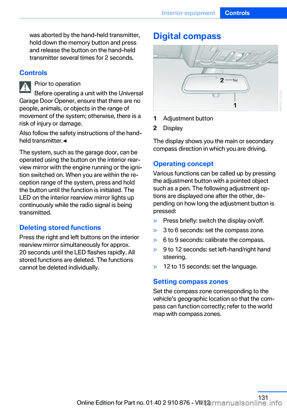
Digital compass1Adjustment button2Display
The display shows you the main or secondary
compass direction in which you are driving.
Operating concept
Various functions can be called up by pressing
the adjustment button with a pointed object
such as a pen. The following adjustment op‐
tions are displayed one after the other, de‐
pending on how long the adjustment button is
pressed:
▷Press briefly: switch the display on/off.▷3 to 6 seconds: set the compass zone.▷6 to 9 seconds: calibrate the compass.▷9 to 12 seconds: set left-hand/right hand
steering.▷12 to 15 seconds: set the language.
Setting compass zones
Set the compass zone corresponding to the
vehicle's geographic location so that the com‐
pass can function correctly; refer to the world
map with compass zones.
Seite 131Interior equipmentControls131
Online Edition for Part no. 01 40 2 910 876 - VII/13
Page 132 of 323
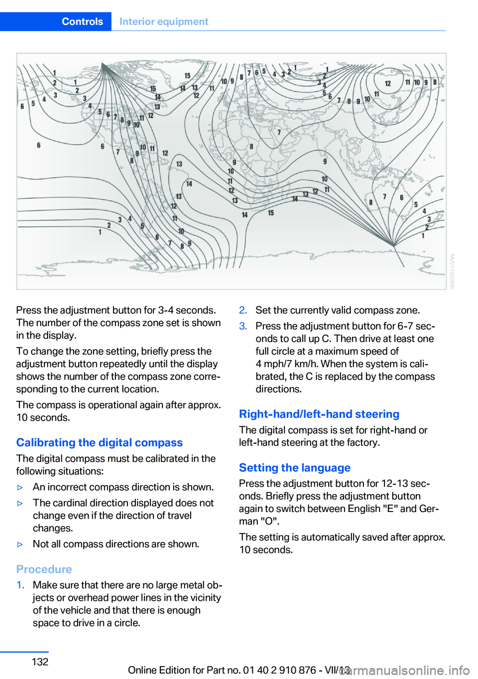
Press the adjustment button for 3‑4 seconds.
The number of the compass zone set is shown
in the display.
To change the zone setting, briefly press the
adjustment button repeatedly until the display
shows the number of the compass zone corre‐
sponding to the current location.
The compass is operational again after approx.
10 seconds.
Calibrating the digital compass
The digital compass must be calibrated in the
following situations:▷An incorrect compass direction is shown.▷The cardinal direction displayed does not
change even if the direction of travel
changes.▷Not all compass directions are shown.
Procedure
1.Make sure that there are no large metal ob‐
jects or overhead power lines in the vicinity
of the vehicle and that there is enough
space to drive in a circle.2.Set the currently valid compass zone.3.Press the adjustment button for 6‑7 sec‐
onds to call up C. Then drive at least one
full circle at a maximum speed of
4 mph/7 km/h. When the system is cali‐
brated, the C is replaced by the compass
directions.
Right-hand/left-hand steering
The digital compass is set for right-hand or
left-hand steering at the factory.
Setting the language Press the adjustment button for 12‑13 sec‐
onds. Briefly press the adjustment button
again to switch between English "E" and Ger‐
man "O".
The setting is automatically saved after approx.
10 seconds.
Seite 132ControlsInterior equipment132
Online Edition for Part no. 01 40 2 910 876 - VII/13
Page 133 of 323
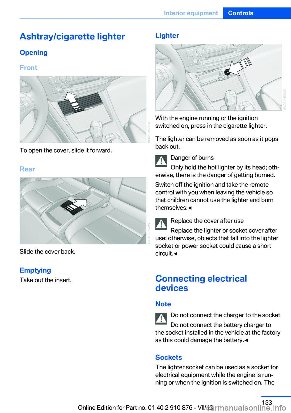
Ashtray/cigarette lighterOpening
Front
To open the cover, slide it forward.
Rear
Slide the cover back.
Emptying Take out the insert.
Lighter
With the engine running or the ignition
switched on, press in the cigarette lighter.
The lighter can be removed as soon as it pops
back out.
Danger of burns
Only hold the hot lighter by its head; oth‐
erwise, there is the danger of getting burned.
Switch off the ignition and take the remote
control with you when leaving the vehicle so
that children cannot use the lighter and burn
themselves.◀
Replace the cover after use
Replace the lighter or socket cover after
use; otherwise, objects that fall into the lighter
socket or power socket could cause a short
circuit.◀
Connecting electrical
devices
Note Do not connect the charger to the socket
Do not connect the battery charger to
the socket installed in the vehicle at the factory
as this could damage the battery.◀
Sockets
The lighter socket can be used as a socket for
electrical equipment while the engine is run‐
ning or when the ignition is switched on. The
Seite 133Interior equipmentControls133
Online Edition for Part no. 01 40 2 910 876 - VII/13
Page 134 of 323
total load of all sockets must not exceed
140 watts at 12 volt.
Avoid damaging the sockets by attempting to
insert plugs of unsuitable shape or size.
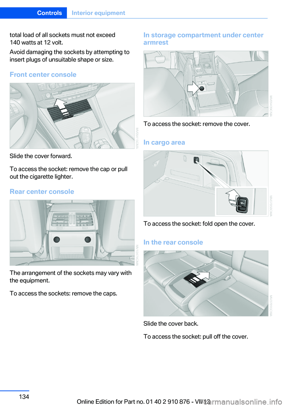
Front center console
Slide the cover forward.
To access the socket: remove the cap or pull
out the cigarette lighter.
Rear center console
The arrangement of the sockets may vary with
the equipment.
To access the sockets: remove the caps.
In storage compartment under center
armrest
To access the socket: remove the cover.
In cargo area
To access the socket: fold open the cover.
In the rear console
Slide the cover back.
To access the socket: pull off the cover.
Seite 134ControlsInterior equipment134
Online Edition for Part no. 01 40 2 910 876 - VII/13
Page 135 of 323
Cargo area
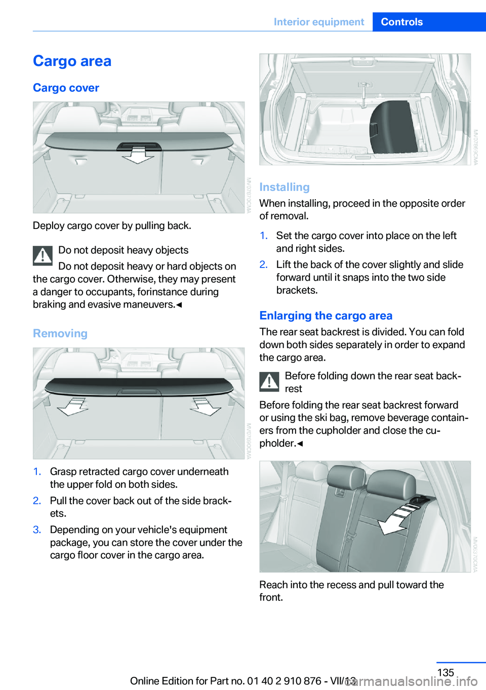
Cargo cover
Deploy cargo cover by pulling back. Do not deposit heavy objects
Do not deposit heavy or hard objects on
the cargo cover. Otherwise, they may present
a danger to occupants, for instance during
braking and evasive maneuvers.◀
Removing
1.Grasp retracted cargo cover underneath
the upper fold on both sides.2.Pull the cover back out of the side brack‐
ets.3.Depending on your vehicle's equipment
package, you can store the cover under the
cargo floor cover in the cargo area.
Installing
When installing, proceed in the opposite order
of removal.
1.Set the cargo cover into place on the left
and right sides.2.Lift the back of the cover slightly and slide
forward until it snaps into the two side
brackets.
Enlarging the cargo area
The rear seat backrest is divided. You can fold
down both sides separately in order to expand
the cargo area.
Before folding down the rear seat back‐
rest
Before folding the rear seat backrest forward
or using the ski bag, remove beverage contain‐
ers from the cupholder and close the cu‐
pholder.◀
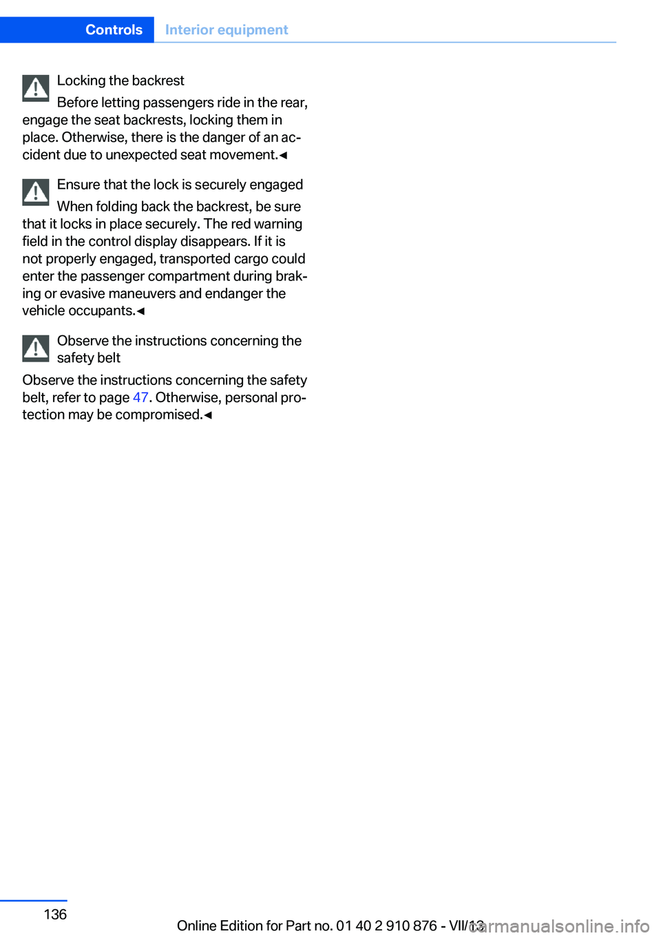
Reach into the recess and pull toward the
front.
Seite 135Interior equipmentControls135
Online Edition for Part no. 01 40 2 910 876 - VII/13
Page 136 of 323
Locking the backrest
Before letting passengers ride in the rear,
engage the seat backrests, locking them in
place. Otherwise, there is the danger of an ac‐
cident due to unexpected seat movement.◀
Ensure that the lock is securely engagedWhen folding back the backrest, be sure
that it locks in place securely. The red warning
field in the control display disappears. If it is
not properly engaged, transported cargo could
enter the passenger compartment during brak‐
ing or evasive maneuvers and endanger the
vehicle occupants.◀
Observe the instructions concerning the
safety belt
Observe the instructions concerning the safety
belt, refer to page 47. Otherwise, personal pro‐
tection may be compromised.◀Seite 136ControlsInterior equipment136
Online Edition for Part no. 01 40 2 910 876 - VII/13
Page 137 of 323
Storage compartmentsVehicle equipmentThis chapter describes all series equipment as
well as country-specific and special equipment
offered for this model series.Therefore, it also
describes equipment that may not be found in
your vehicle, for instance due to the selected
special equipment or the country version. This
also applies to safety-related functions and
systems.
Notes No loose objects in the passenger com‐
partment
Do not stow any objects in the passenger
compartment without securing them; other‐
wise, they may present a danger to occupants
for instance during braking and avoidance ma‐ neuvers.◀
No non-slip mats on the dashboard
Do not use non-slip materials, such as
non-slip mats, on the dashboard, or it could be
damaged by the substances in the materials.◀Glove compartment
Opening
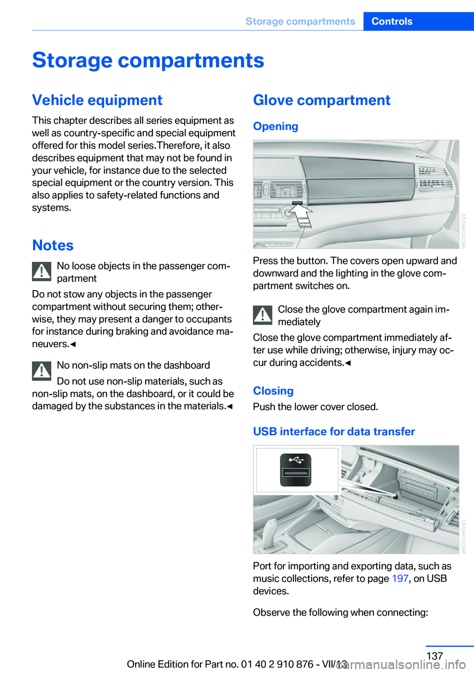
Press the button. The covers open upward and
downward and the lighting in the glove com‐
partment switches on.
Close the glove compartment again im‐
mediately
Close the glove compartment immediately af‐
ter use while driving; otherwise, injury may oc‐
cur during accidents.◀
ClosingPush the lower cover closed.
USB interface for data transfer
Port for importing and exporting data, such as
music collections, refer to page 197, on USB
devices.
Observe the following when connecting:
Seite 137Storage compartmentsControls137
Online Edition for Part no. 01 40 2 910 876 - VII/13
Page 138 of 323
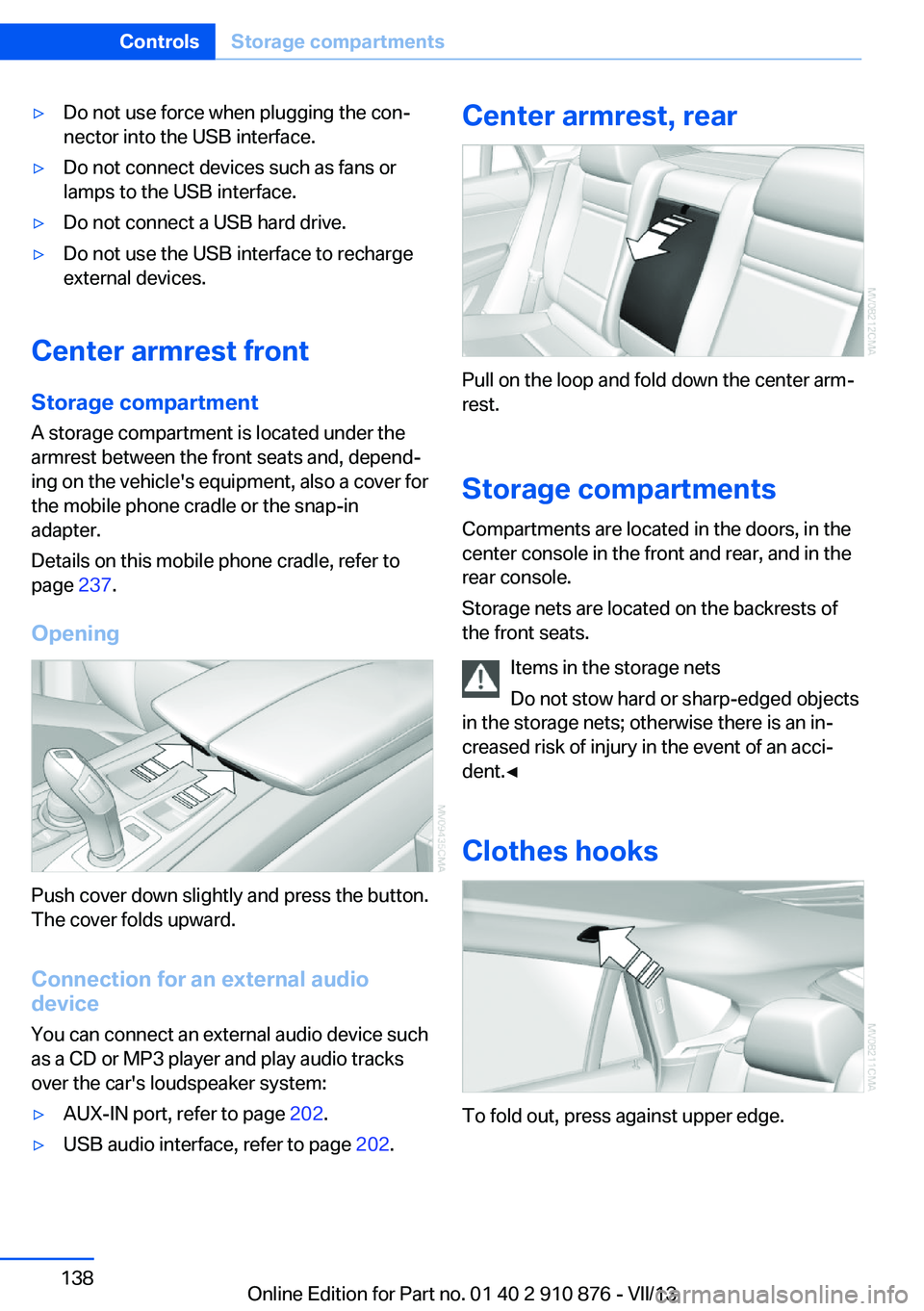
▷Do not use force when plugging the con‐
nector into the USB interface.▷Do not connect devices such as fans or
lamps to the USB interface.▷Do not connect a USB hard drive.▷Do not use the USB interface to recharge
external devices.
Center armrest front
Storage compartment A storage compartment is located under the
armrest between the front seats and, depend‐
ing on the vehicle's equipment, also a cover for
the mobile phone cradle or the snap-in
adapter.
Details on this mobile phone cradle, refer to
page 237.
Opening
Push cover down slightly and press the button.
The cover folds upward.
Connection for an external audio
device
You can connect an external audio device such
as a CD or MP3 player and play audio tracks over the car's loudspeaker system:
▷AUX-IN port, refer to page 202.▷USB audio interface, refer to page 202.Center armrest, rear
Pull on the loop and fold down the center arm‐
rest.
Storage compartments Compartments are located in the doors, in the
center console in the front and rear, and in the
rear console.
Storage nets are located on the backrests of
the front seats.
Items in the storage nets
Do not stow hard or sharp-edged objects
in the storage nets; otherwise there is an in‐
creased risk of injury in the event of an acci‐
dent.◀
Clothes hooks
To fold out, press against upper edge.
Seite 138ControlsStorage compartments138
Online Edition for Part no. 01 40 2 910 876 - VII/13
Page 139 of 323
Do not obstruct view
When suspending clothing from the
hooks, ensure that it will not obstruct the driv‐
er's vision.◀
No heavy objects
Do not hang heavy objects from the
hooks; otherwise, they may present a danger
to passengers during braking and evasive ma‐
neuvers.◀
Cupholders
Notes Shatter-proof containers and no hot
drinks
Use light and shatter-proof containers and do
not transport hot drinks. Otherwise, there is
the increased danger of injury in an accident.◀
Unsuitable containers
Do not forcefully push unsuitable con‐
tainers into the cupholders. This may result in
damage.◀
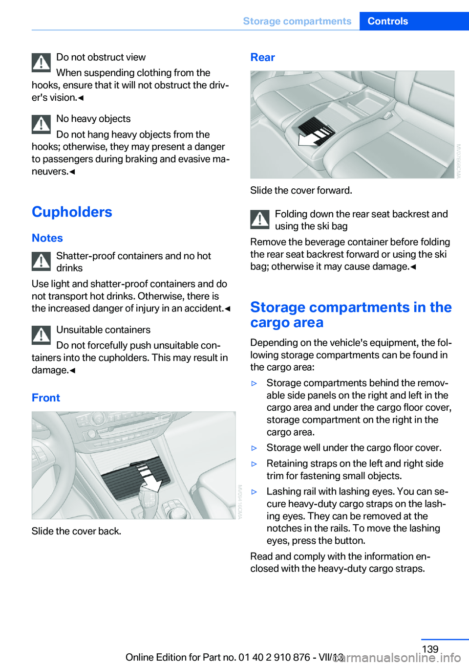
Front
Slide the cover back.
Rear
Slide the cover forward. Folding down the rear seat backrest and
using the ski bag
Remove the beverage container before folding
the rear seat backrest forward or using the ski
bag; otherwise it may cause damage.◀
Storage compartments in the
cargo area
Depending on the vehicle's equipment, the fol‐
lowing storage compartments can be found in
the cargo area:
▷Storage compartments behind the remov‐
able side panels on the right and left in the
cargo area and under the cargo floor cover,
storage compartment on the right in the
cargo area.▷Storage well under the cargo floor cover.▷Retaining straps on the left and right side
trim for fastening small objects.▷Lashing rail with lashing eyes. You can se‐
cure heavy-duty cargo straps on the lash‐
ing eyes. They can be removed at the
notches in the rails. To move the lashing
eyes, press the button.
Read and comply with the information en‐
closed with the heavy-duty cargo straps.
Seite 139Storage compartmentsControls139
Online Edition for Part no. 01 40 2 910 876 - VII/13
Page 140 of 323
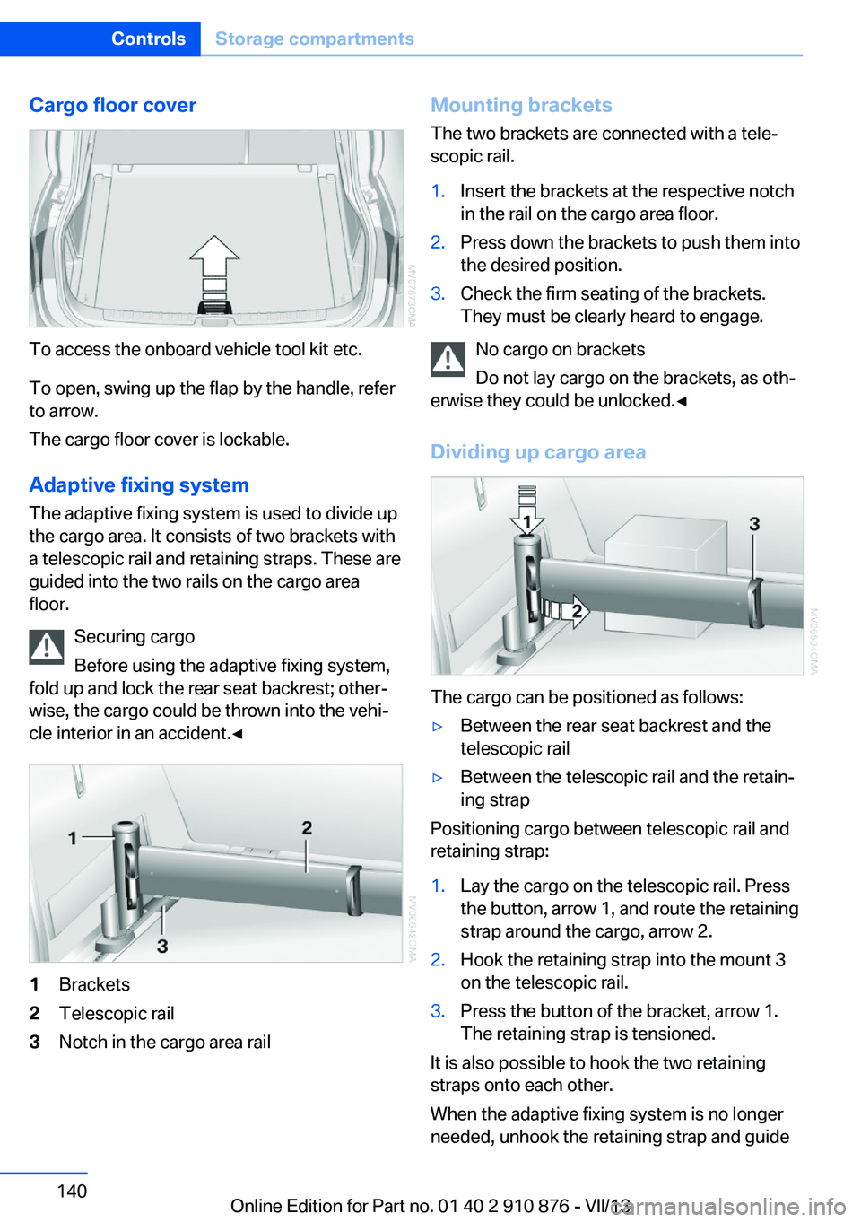
Cargo floor cover
To access the onboard vehicle tool kit etc.
To open, swing up the flap by the handle, refer
to arrow.
The cargo floor cover is lockable.
Adaptive fixing system The adaptive fixing system is used to divide up
the cargo area. It consists of two brackets with
a telescopic rail and retaining straps. These are
guided into the two rails on the cargo area
floor.
Securing cargo
Before using the adaptive fixing system,
fold up and lock the rear seat backrest; other‐
wise, the cargo could be thrown into the vehi‐
cle interior in an accident.◀
1Brackets2Telescopic rail3Notch in the cargo area railMounting brackets
The two brackets are connected with a tele‐
scopic rail.1.Insert the brackets at the respective notch
in the rail on the cargo area floor.2.Press down the brackets to push them into
the desired position.3.Check the firm seating of the brackets.
They must be clearly heard to engage.
No cargo on brackets
Do not lay cargo on the brackets, as oth‐
erwise they could be unlocked.◀
Dividing up cargo area
The cargo can be positioned as follows:
▷Between the rear seat backrest and the
telescopic rail▷Between the telescopic rail and the retain‐
ing strap
Positioning cargo between telescopic rail and
retaining strap:
1.Lay the cargo on the telescopic rail. Press
the button, arrow 1, and route the retaining
strap around the cargo, arrow 2.2.Hook the retaining strap into the mount 3
on the telescopic rail.3.Press the button of the bracket, arrow 1.
The retaining strap is tensioned.
It is also possible to hook the two retaining
straps onto each other.
When the adaptive fixing system is no longer
needed, unhook the retaining strap and guide
Seite 140ControlsStorage compartments140
Online Edition for Part no. 01 40 2 910 876 - VII/13