BMW Z8 CONVERTIBLE 2002 Owners Manual
Manufacturer: BMW, Model Year: 2002, Model line: Z8 CONVERTIBLE, Model: BMW Z8 CONVERTIBLE 2002Pages: 174, PDF Size: 2.37 MB
Page 141 of 174
141n
IndexDataTechnologyRepairsCar careControlsOverview
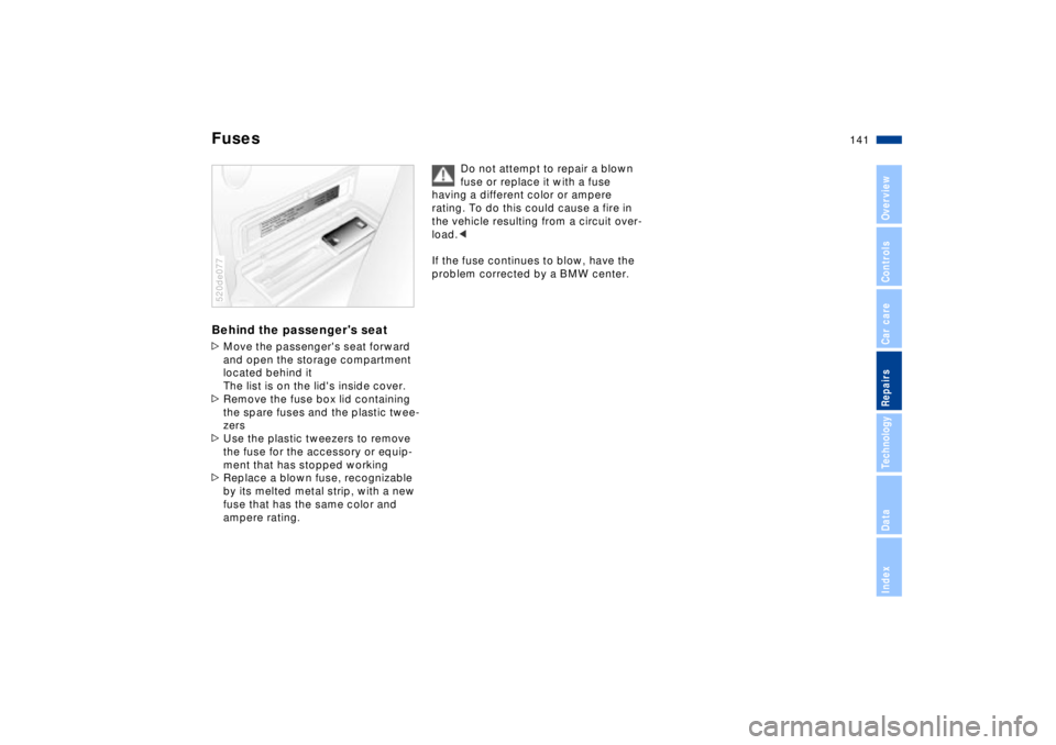
FusesBehind the passenger's seat>Move the passenger's seat forward
and open the storage compartment
located behind it
The list is on the lid's inside cover.
>Remove the fuse box lid containing
the spare fuses and the plastic twee-
zers
>Use the plastic tweezers to remove
the fuse for the accessory or equip-
ment that has stopped working
>Replace a blown fuse, recognizable
by its melted metal strip, with a new
fuse that has the same color and
ampere rating.520de077
Do not attempt to repair a blown
fuse or replace it with a fuse
having a different color or ampere
rating. To do this could cause a fire in
the vehicle resulting from a circuit over-
load.<
If the fuse continues to blow, have the
problem corrected by a BMW center.
Page 142 of 174
142n
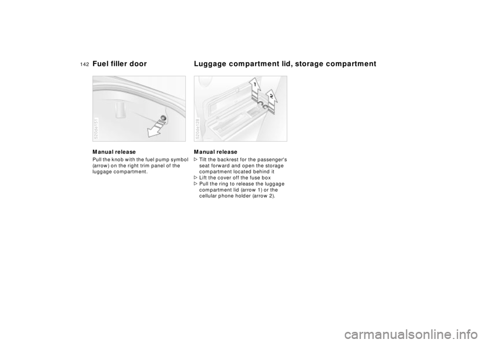
Manual release Pull the knob with the fuel pump symbol
(arrow) on the right trim panel of the
luggage compartment. 520de151
Manual release >Tilt the backrest for the passenger's
seat forward and open the storage
compartment located behind it
>Lift the cover off the fuse box
>Pull the ring to release the luggage
compartment lid (arrow 1) or the
cellular phone holder (arrow 2). 520de128
Fuel filler door Luggage compartment lid, storage compartment
Page 143 of 174
143n
IndexDataTechnologyRepairsCar careControlsOverview
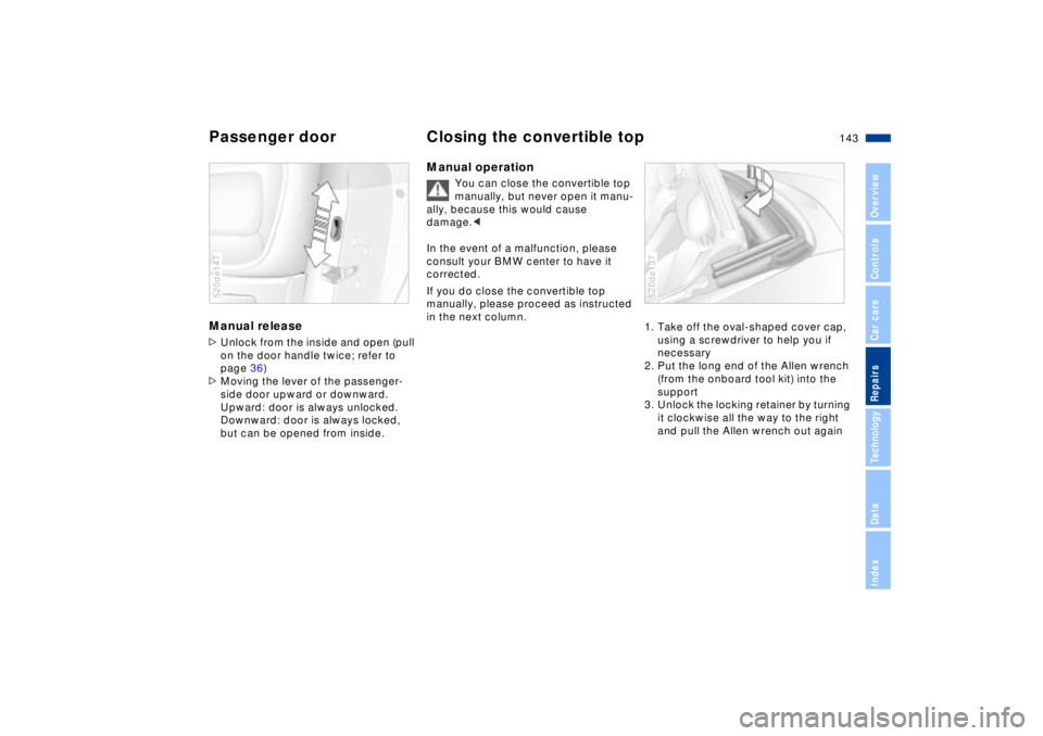
Passenger door Closing the convertible topManual release >Unlock from the inside and open (pull
on the door handle twice; refer to
page 36)
>Moving the lever of the passenger-
side door upward or downward.
Upward: door is always unlocked.
Downward: door is always locked,
but can be opened from inside.520de147
Manual operation
You can close the convertible top
manually, but never open it manu-
ally, because this would cause
damage.<
In the event of a malfunction, please
consult your BMW center to have it
corrected.
If you do close the convertible top
manually, please proceed as instructed
in the next column.
1. Take off the oval-shaped cover cap,
using a screwdriver to help you if
necessary
2. Put the long end of the Allen wrench
(from the onboard tool kit) into the
support
3. Unlock the locking retainer by turning
it clockwise all the way to the right
and pull the Allen wrench out again 520de137
Page 144 of 174
144n
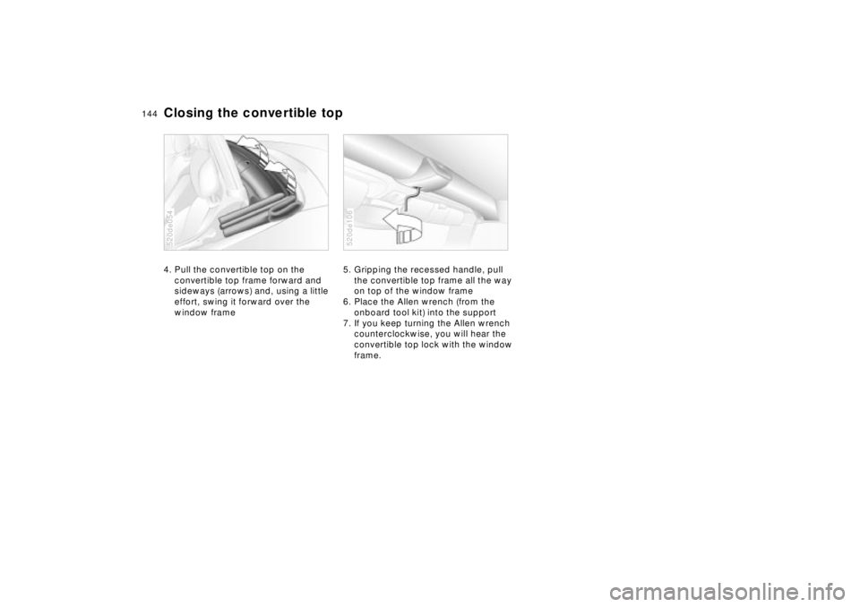
Closing the convertible top4. Pull the convertible top on the
convertible top frame forward and
sideways (arrows) and, using a little
effort, swing it forward over the
window frame520de054
5. Gripping the recessed handle, pull
the convertible top frame all the way
on top of the window frame
6. Place the Allen wrench (from the
onboard tool kit) into the support
7. If you keep turning the Allen wrench
counterclockwise, you will hear the
convertible top lock with the window
frame.520de106
Page 145 of 174
145n
IndexDataTechnologyRepairsCar careControlsOverview
Do not use spray starter fluids to start
the engine.
If the battery is discharged, the engine
can be started with the use of two
jumper cables and the battery of
another vehicle. You can also use the
same method to help start another
vehicle. Use only jumper cables with
fully insulated grips on the terminal
clamps.
Do not touch high-voltage wiring
and cables on a running engine.
There is a risk of fatal injury if you do
this. Carefully comply with the following
instructions to avoid personal injury or
damage to one or both vehicles.<
1. Ensure that the battery in the support
vehicle is also rated at 12 volts. This
information is provided on the top of
the battery casing
2 Do not disconnect your battery from
your vehicle's electrical system.
Switch off all electrical accessories in
both vehicles
3 Make absolutely certain that there is
no contact between the bodywork of
the two vehicles Ð short circuit hazard
4 Start the engine on the support
vehicle and allow it to run
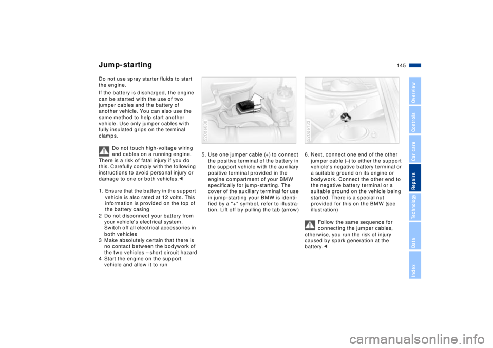
5. Use one jumper cable (+) to connect
the positive terminal of the battery in
the support vehicle with the auxiliary
positive terminal provided in the
engine compartment of your BMW
specifically for jump-starting. The
cover of the auxiliary terminal for use
in jump-starting your BMW is identi-
fied by a "+" symbol, refer to illustra-
tion. Lift off by pulling the tab (arrow) 520de088
6. Next, connect one end of the other
jumper cable (Ð) to either the support
vehicle's negative battery terminal or
a suitable ground on its engine or
bodywork. Connect the other end to
the negative battery terminal or a
suitable ground on the vehicle being
started. There is a special nut
provided for this on the BMW (see
illustration)
Follow the same sequence for
connecting the jumper cables,
otherwise, you run the risk of injury
caused by spark generation at the
battery.<520de133
Jump-starting
Page 146 of 174
146n
Jump-starting Towing the vehicle7. Start the support vehicle's engine
and let it run at an increased idling
speed for a few minites. Start the
engine on the vehicle needing the
jump-start, and allow it to run as
usual. If the first start attempt is not
successful, wait a few minutes
before another attempt in order to
allow the discharged battery to
recharge
8. Before disconnecting the jumper
cables let the engines run for a few
minutes
9. Then disconnect the jumper cables
in reverse sequence.
Depending on the cause of the fault,
have the battery recharged by your
BMW center.
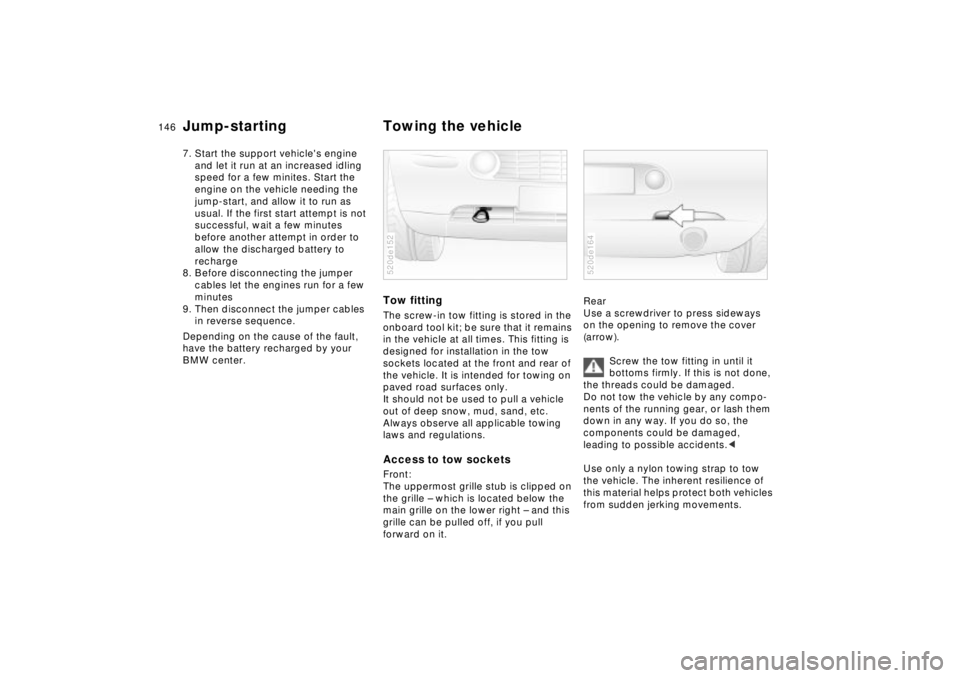
Tow fittingThe screw-in tow fitting is stored in the
onboard tool kit; be sure that it remains
in the vehicle at all times. This fitting is
designed for installation in the tow
sockets located at the front and rear of
the vehicle. It is intended for towing on
paved road surfaces only.
It should not be used to pull a vehicle
out of deep snow, mud, sand, etc.
Always observe all applicable towing
laws and regulations.Access to tow socketsFront:
The uppermost grille stub is clipped on
the grille Ð which is located below the
main grille on the lower right Ð and this
grille can be pulled off, if you pull
forward on it.520de152
Rear
Use a screwdriver to press sideways
on the opening to remove the cover
(arrow).
Screw the tow fitting in until it
bottoms firmly. If this is not done,
the threads could be damaged.
Do not tow the vehicle by any compo-
nents of the running gear, or lash them
down in any way. If you do so, the
components could be damaged,
leading to possible accidents.<
Use only a nylon towing strap to tow
the vehicle. The inherent resilience of
this material helps protect both vehicles
from sudden jerking movements.520de164
Page 147 of 174
147n
IndexDataTechnologyRepairsCar careControlsOverview
Towing the vehicle
Avoid "off-center" towing. Be sure
that the tow rope is pulled tightly
when the towing vehicle begins to
move.<
The towed vehicle should always
be the lighter of the two vehicles.
If this is not the case, it is no longer
possible to control vehicle response.<
Tow-startingFor instructions on jump-starting, refer
to page 145.
Never attempt to use your vehicle to
push another vehicle, since damage to
the energy-absorbing bumpers could
result.
Towing a vehicle1. Put the shift lever in neutral
2. Towing speed:
Max. 45 mph (70 km/h)
3. Towing distance:
Max. 95 miles (150 km)
4. Leave the ignition key in position 1 to
ensure that the brake lamps, turn
signals, horn and windshield wipers
remain operative, and to prevent the
steering lock detent from engaging
5. Switch on the hazard warning system
(comply with country-specific regula-
tions).
Find some means of identifying the
vehicle in tow, e. g. place a sign or
warning triangle in the rear window.
Make sure that the ignition key
remains in position 1 even when
the electrical system has failed to
prevent the steering lock from
engaging. The steering and brakes are
without power assist when the engine is
not running. This means that increased
effort is required for steering and
braking.<
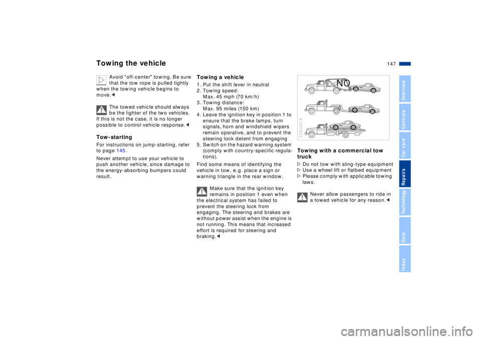
Towing with a commercial tow
truck>Do not tow with sling-type equipment
>Use a wheel lift or flatbed equipment
>Please comply with applicable towing
laws.
Never allow passengers to ride in
a towed vehicle for any reason.<520us014
Page 148 of 174
148n
Page 149 of 174
Overview
Controls and features
Operation, care
and maintenance
Owner service procedures
Technical data
Index Advanced technology
149n
IndexDataTechnologyRepairsCar careControlsOverview
Airbags150
Car radio reception151
Dynamic Stability Control
(DSC)152
Safety belt tensioner153
Interior rearview mirror with
automatic dimmer154
Xenon lamps155
Tech-
Page 150 of 174
150n
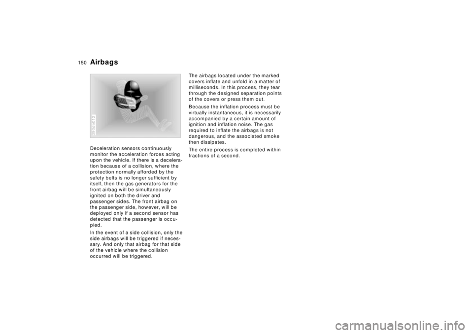
Deceleration sensors continuously
monitor the acceleration forces acting
upon the vehicle. If there is a decelera-
tion because of a collision, where the
protection normally afforded by the
safety belts is no longer sufficient by
itself, then the gas generators for the
front airbag will be simultaneously
ignited on both the driver and
passenger sides. The front airbag on
the passenger side, however, will be
deployed only if a second sensor has
detected that the passenger is occu-
pied.
In the event of a side collision, only the
side airbags will be triggered if neces-
sary. And only that airbag for that side
of the vehicle where the collision
occurred will be triggered.
390de012
The airbags located under the marked
covers inflate and unfold in a matter of
milliseconds. In this process, they tear
through the designed separation points
of the covers or press them out.
Because the inflation process must be
virtually instantaneous, it is necessarily
accompanied by a certain amount of
ignition and inflation noise. The gas
required to inflate the airbags is not
dangerous, and the associated smoke
then dissipates.
The entire process is completed within
fractions of a second.
Airbags