ECO mode BUICK ENCLAVE 2010 Owner's Guide
[x] Cancel search | Manufacturer: BUICK, Model Year: 2010, Model line: ENCLAVE, Model: BUICK ENCLAVE 2010Pages: 438, PDF Size: 2.47 MB
Page 233 of 438
Climate Controls 8-1
Climate Controls
Climate Control Systems
Dual Automatic ClimateControl System . . . . . . . . . . . . . . 8-1
Rear Climate Control System (Rear Climate
Control Only) . . . . . . . . . . . . . . . . 8-7
Rear Climate Control System (Rear Climate with RearSeat Audio) . . . . . . . . . . . . . . . . . 8-8
Air Vents
Air Vents . . . . . . . . . . . . . . . . . . . . . . 8-9
Climate Control Systems
Dual Automatic Climate Control System
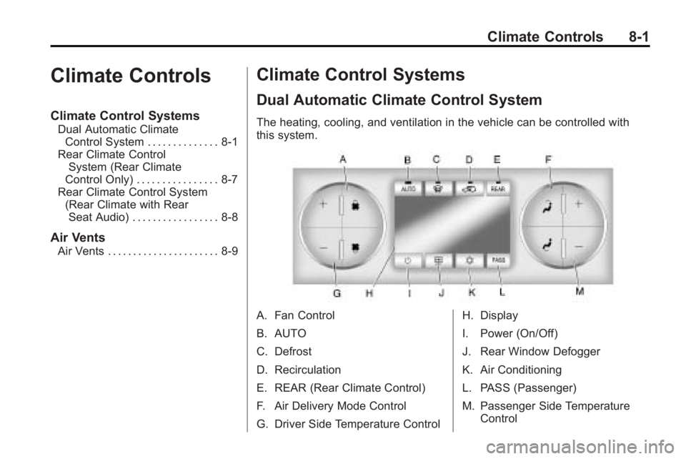
The heating, cooling, and ventilation in the vehicle can be controlled with
this system.
A. Fan Control
B. AUTO
C. Defrost
D. Recirculation
E. REAR (Rear Climate Control)
F. Air Delivery Mode Control
G. Driver Side Temperature Control H. Display
I. Power (On/Off)
J. Rear Window Defogger
K. Air Conditioning
L. PASS (Passenger)
M. Passenger Side Temperature
Control
Page 234 of 438
8-2 Climate Controls
Display Function
Each time the temperature, mode,
or fan control buttons are pressed,
the climate control display shows
that function along with the inside
temperature setting. The outside
temperature is displayed on the
instrument panel cluster.
O(On/Off):Press to turn the
climate control system on or off.
While the system is off, outside air
still enters through the floor outlets,
but the air delivery mode can be
adjusted.
The climate control system will also
turn on if either the fan control,
defrost, AUTO, or air conditioning
buttons are pressed.
Automatic Operation
AUTO (Automatic): The system
automatically controls the inside
temperature, the air delivery, and
the fan speed. To use automatic mode:
1. Press the AUTO button.
When AUTO is selected, the
current temperature(s) selected
and AUTO is shown on the
display. The current air delivery
mode and fan speed also
appear for approximately
five seconds.
When AUTO is selected, the air
conditioning and air inlet are
automatically controlled. The air
conditioning runs when the
outside temperature is over
4°C (40°F). The system is
automatically set to outside air,
unless it is hot outside and
then the air inlet changes to
recirculation mode to help
quickly cool the vehicle. The
recirculation indicator light will
come on. 2. Set the temperature for the
driver and passenger.
To find a comfortable setting,
start with a 22°C (73°F)
temperature setting and allow
about 20 minutes for the system
to regulate. Use the driver's side
or passenger side temperature
buttons to adjust the
temperature setting as
necessary. The system will
remain at the selected setting.
Choosing the warmest or coolest
temperatures does not cause the
vehicle to heat or cool more
quickly.
To avoid blowing cold air in cold
weather, the system delays
turning on the fan until warm air
is available. Press the fan
control to override this delay and
select the fan speed.
Page 236 of 438
8-4 Climate Controls
6(Floor):Air is directed to the
floor outlets, with some of the air
directed to the windshield, side
window, and second row floor
outlets. In this mode, the system
uses outside air.
-(Defog): This mode clears the
windows of fog or moisture. Air is
directed to the windshield, floor
outlets, and side window vents.
When this mode is selected, the
system turns off recirculation and
runs the air conditioning compressor
unless the outside temperature is
less than 4°C (40°F). Do not drive
the vehicle until all the windows are
clear.
0(Defrost): Press to turn the
defrost on or off. This mode quickly
clears the windshield of fog or frost.
Air is directed to the windshield,
side window, and floor vents. In this mode, outside air is pulled
inside the vehicle. The air
conditioning system runs
automatically in this setting, unless
the outside temperature is less than
4°C (40°F).
Do not drive the vehicle until all the
windows are clear.
While in defrost mode, if the PASS
button is pressed, the PASS button
indicator flashes three times to
show that the passenger climate
control system cannot be activated.
If the passenger temperature
buttons are adjusted while in
defrost mode, the driver
temperature indicator will change.
The passenger temperature will not
be displayed.
When returning to bi-level, vent,
or floor mode, the previous
temperature settings displays in
place of any change made while in
defrost mode.
Air Conditioning
#(Air Conditioning):
Press to
turn the air conditioning (A/C) on
and off. An indicator light comes on
when A/C is on.
The A/C does not work when the
outside temperature is below
4°C (40°F). If
#is pressed the
indicator flashes three times and
turns off to show that the A/C mode
is not available. If the A/C is on and
the outside temperature drops
below a temperature which is too
cool for air conditioning to be
effective, the A/C indicator turns off
to show that the A/C mode has
been canceled.
On hot days, open the windows
briefly to let hot inside air escape.
This helps reduce the time it takes
for the interior of the vehicle to
cool down.
Page 243 of 438
Driving and Operating 9-1
Driving and
Operating
Driving Information
Defensive Driving . . . . . . . . . . . . . 9-2
Drunk Driving . . . . . . . . . . . . . . . . . 9-2
Control of a Vehicle . . . . . . . . . . . 9-3
Braking . . . . . . . . . . . . . . . . . . . . . . . 9-3
Steering . . . . . . . . . . . . . . . . . . . . . . . 9-4
Off-Road Recovery . . . . . . . . . . . . 9-5
Loss of Control . . . . . . . . . . . . . . . . 9-5
Driving on Wet Roads . . . . . . . . . 9-6
Highway Hypnosis . . . . . . . . . . . . 9-7
Hill and Mountain Roads . . . . . . 9-8
Winter Driving . . . . . . . . . . . . . . . . . 9-9
If the Vehicle is Stuck . . . . . . . . 9-11
Vehicle Load Limits . . . . . . . . . . 9-12
Starting and Operating
New Vehicle Break-In . . . . . . . . 9-16
Ignition Positions . . . . . . . . . . . . 9-16
Retained AccessoryPower (RAP) . . . . . . . . . . . . . . . 9-17
Starting the Engine . . . . . . . . . . 9-18
Engine Heater . . . . . . . . . . . . . . . 9-19 Shifting Into Park . . . . . . . . . . . . 9-20
Shifting Out of Park . . . . . . . . . . 9-21
Parking Over Things
That Burn . . . . . . . . . . . . . . . . . . 9-21
Engine Exhaust
Engine Exhaust . . . . . . . . . . . . . . 9-22
Running the Vehicle WhileParked . . . . . . . . . . . . . . . . . . . . . 9-22
Automatic Transmission
Automatic Transmission . . . . . 9-23
Manual Mode . . . . . . . . . . . . . . . . 9-25
Tow/Haul Mode . . . . . . . . . . . . . . 9-25
Drive Systems
All-Wheel Drive . . . . . . . . . . . . . . 9-26
Brakes
Antilock BrakeSystem (ABS) . . . . . . . . . . . . . . 9-26
Parking Brake . . . . . . . . . . . . . . . 9-27
Brake Assist . . . . . . . . . . . . . . . . . 9-28
Ride Control Systems
StabiliTrak System . . . . . . . . . . . 9-28
Cruise Control
Cruise Control . . . . . . . . . . . . . . . 9-30
Object Detection Systems
Ultrasonic Parking Assist . . . . 9-33
Rear Vision Camera (RVC) . . . . . . . . . . . . . 9-34
Fuel
Fuel . . . . . . . . . . . . . . . . . . . . . . . . . 9-39
Recommended Fuel . . . . . . . . . 9-40
Gasoline Specifications . . . . . . 9-40
California FuelRequirements . . . . . . . . . . . . . . 9-40
Fuels in Foreign Countries . . . 9-40
Fuel Additives . . . . . . . . . . . . . . . 9-41
Filling the Tank . . . . . . . . . . . . . . 9-42
Filling a Portable Fuel Container . . . . . . . . . . . . . . . . . . . 9-44
Towing
General TowingInformation . . . . . . . . . . . . . . . . . 9-44
Driving Characteristics and Towing Tips . . . . . . . . . . . . . . . . 9-45
Trailer Towing . . . . . . . . . . . . . . . . 9-50
Towing Equipment . . . . . . . . . . . 9-53
Conversions and Add-Ons
Add-On Electrical Equipment . . . . . . . . . . . . . . . . . 9-55
Page 261 of 438
Driving and Operating 9-19
Notice:The engine is designed to
work with the electronics in the
vehicle. If you add electrical parts
or accessories, you could change
the way the engine operates.
Before adding electrical
equipment, check with your
dealer/retailer. If you do not, the
engine might not perform
properly. Any resulting damage
would not be covered by the
vehicle warranty.
Engine Heater
The engine coolant heater can
provide easier starting and better
fuel economy during engine
warm-up in cold weather conditions
at or below 0°F (−18°C). Vehicles
with an engine coolant heater
should be plugged in at least four
hours before starting. Some models
may have an internal thermostat in
the cord which will prevent engine
coolant heater operation at
temperatures above 0°F (−18°C).
To Use the Engine Coolant
Heater
1. Turn off the engine.
2. Open the hood and unwrap the
electrical cord. The cord is
located on the driver side of the
engine compartment. It is routed
around the windshield washer
fluid reservoir.
3. Plug the cord into a normal, grounded 110-volt AC outlet.
{WARNING
Plugging the cord into an
ungrounded outlet could cause an
electrical shock. Also, the wrong
kind of extension cord could
overheat and cause a fire. You
could be seriously injured. Plug
the cord into a properly grounded
three-prong 110-volt AC outlet.
If the cord will not reach, use a
heavy-duty three-prong extension
cord rated for at least 15 amps. 4. Before starting the engine, be
sure to unplug and store the
cord as it was before to keep it
away from moving engine parts.
If you do not, it could be
damaged.
The length of time the heater should
remain plugged in depends on
several factors. Ask a dealer/retailer
in the area where you will be
parking the vehicle for the best
advice on this.
Page 289 of 438
Driving and Operating 9-47
Tow/Haul Mode
Tow/Haul assists when pulling a
heavy trailer or a large or heavy
load. The purpose of the Tow/Haul
mode is to:
.Reduce the frequency and
improve the predictability of
transmission shifts.
.Provide the same solid shift feel
as when the vehicle is unloaded.
.Improve control of vehicle speed
while requiring less throttle pedal
activity.
.Increase the charging system
voltage to assist in recharging a
battery installed in a trailer.
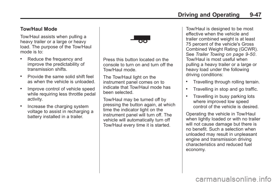
Press this button located on the
console to turn on and turn off the
Tow/Haul mode.
The Tow/Haul light on the
instrument panel comes on to
indicate that Tow/Haul mode has
been selected.
Tow/Haul may be turned off by
pressing the button again, at which
time the indicator light on the
instrument panel will turn off. The
vehicle will automatically turn off
Tow/Haul every time it is started.Tow/Haul is designed to be most
effective when the vehicle and
trailer combined weight is at least
75 percent of the vehicle's Gross
Combined Weight Rating (GCWR).
See
Trailer Towing
on page 9‑50.
Tow/Haul is most useful when
pulling a heavy trailer or a large or
heavy load under the following
driving conditions:
.Travelling through rolling terrain.
.Travelling in stop and go traffic.
.Travelling in busy parking lots
where improved low speed
control of the vehicle is desired.
Operating the vehicle in Tow/Haul
when lightly loaded or with no trailer
will not cause damage but there is
no benefit. Such a selection when
unloaded may result in unpleasant
engine and transmission driving
characteristics and reduced fuel
economy.
Page 297 of 438

Driving and Operating 9-55
They should be connected by your
dealer/retailer or a qualified service
center.
If the back-up lamp circuit is not
functional, contact your dealer/
retailer.
If a remote (non-vehicle) battery is
being charged, press the Tow/Haul
mode switch located on the center
console near the climate controls.
This will boost the vehicle system
voltage and properly charge the
battery. If the trailer is too light for
Tow/Haul mode, turn on the
headlamps (Non-HID only) as a
second way to boost the vehicle
system and charge the battery.Electric Trailer Brake Control
Wiring Provisions
These wiring provisions for an
electric trailer brake controller are
included with the vehicle as part of
the trailer wiring package. The
instrument panel contains blunt cut
wires behind the steering column for
the electric trailer brake controller.
The harness contains the following
wires:
.Red/Black: Power Supply
.White: Brake Switch Signal
.Gray: Illumination
.Dark Blue: Trailer Brake Signal
.Black: Ground
The electric trailer brake controller
should be installed by your dealer/
retailer or a qualified service center.
Conversions and
Add-Ons
Add-On Electrical
Equipment
Notice: Do not add anything
electrical to the vehicle unless
you check with your dealer/
retailer first. Some electrical
equipment can damage the
vehicle and the damage would
not be covered by the vehicle's
warranty. Some add-on electrical
equipment can keep other
components from working as
they should.
Add-on equipment can drain the
vehicle battery, even if the vehicle is
not operating.
The vehicle has an airbag system.
Before attempting to add anything
electrical to the vehicle, see
Servicing the Airbag-Equipped
Vehicle
on page 3‑41and Adding
Equipment to the Airbag-Equipped
Vehicle on page 3‑42.
Page 347 of 438

Vehicle Care 10-49
The TPMS sensors can also be
matched to each tire/wheel position
by increasing or decreasing the
tire's air pressure. If increasing the
tire's air pressure, do not exceed
the maximum inflation pressure
indicated on the tire's sidewall.
To decrease air-pressure out of a
tire you can use the pointed end of
the valve cap, a pencil-style air
pressure gage, or a key.
You have two minutes to match the
first tire/wheel position, and
five minutes overall to match all
four tire/wheel positions. If it takes
longer than two minutes, to match
the first tire and wheel, or more than
five minutes to match all four tire
and wheel positions the matching
process stops and you need to
start over.
The TPMS sensor matching process
is outlined below:
1. Set the parking brake.
2. Turn the ignition switch to ON/RUN with the engine off. 3. Press the Remote Keyless Entry
(RKE) transmitter's LOCK and
UNLOCK buttons at the same
time for approximately
five seconds. The horn sounds
twice to signal the receiver is in
relearn mode and TIRE
LEARNING ACTIVE message
displays on the DIC screen.
4. Start with the driver side front tire.
5. Remove the valve cap from the valve cap stem. Activate the
TPMS sensor by increasing or
decreasing the tire's air pressure
for five seconds, or until a horn
chirp sounds. The horn chirp,
which may take up to
30 seconds to sound, confirms
that the sensor identification
code has been matched to this
tire and wheel position.
6. Proceed to the passenger side front tire, and repeat the
procedure in Step 5. 7. Proceed to the passenger side
rear tire, and repeat the
procedure in Step 5.
8. Proceed to the driver side rear tire, and repeat the procedure in
Step 5. The horn sounds two
times to indicate the sensor
identification code has been
matched to the driver side rear
tire, and the TPMS sensor
matching process is no longer
active. The TIRE LEARNING
ACTIVE message on the DIC
display screen goes off.
9. Turn the ignition switch to LOCK/OFF.
10. Set all four tires to the recommended air pressure
level as indicated on the Tire
and Loading Information label.
11. Put the valve caps back on the valve stems.
Page 421 of 438

Customer Information 13-11
Insuring Your Vehicle
Protect your investment in your GM
vehicle with comprehensive and
collision insurance coverage. There
are significant differences in the
quality of coverage afforded by
various insurance policy terms.
Many insurance policies provide
reduced protection to your GM
vehicle by limiting compensation
for damage repairs by using
aftermarket collision parts. Some
insurance companies will not
specify aftermarket collision parts.
When purchasing insurance, we
recommend that you assure your
vehicle will be repaired with GM
original equipment collision parts.
If such insurance coverage is not
available from your current
insurance carrier, consider switching
to another insurance carrier.If your vehicle is leased, the leasing
company may require you to have
insurance that assures repairs with
Genuine GM Original Equipment
Manufacturer (OEM) parts or
Genuine Manufacturer replacement
parts. Read your lease carefully, as
you may be charged at the end of
your lease for poor quality repairs.
If a Crash Occurs
If there has been an injury, call
emergency services for help. Do not
leave the scene of a crash until all
matters have been taken care of.
Move the vehicle only if its position
puts you in danger, or you are
instructed to move it by a police
officer.
Give only the necessary information
to police and other parties involved
in the crash.
For emergency towing see
What
Will You See After an Airbag
Inflates? on page 3‑35. Gather the following information:
.Driver's name, address, phone
number
.Driver's license number
.Owner's name, address, phone
number
.Vehicle license plate
.Vehicle make, model and
model year
.Vehicle Identification
Number (VIN)
.Insurance company and policy
number
.General description of the
damage to the other vehicle
Choose a reputable repair facility
that uses quality replacement parts.
See “Collision Parts” earlier in this
section.
If the airbag has inflated, see What
Will You See After an Airbag
Inflates? on page 3‑35.
Page 430 of 438
i-4 INDEX
Driving (cont.)Off-Road Recovery . . . . . . . . . . . . 9-5
Vehicle Load Limits . . . . . . . . . . . 9-12
Winter . . . . . . . . . . . . . . . . . . . . . . . . . 9-9
Driving for Better Fuel Economy . . . . . . . . . . . . . . . . . . . . . 1-20
Dual Automatic Climate Control System . . . . . . . . . . . . . . . . 8-1
DVD
Rear Seat EntertainmentSystem . . . . . . . . . . . . . . . . . . . . . . 7-34
DVD/CD Player . . . . . . . . . . . . . . . . 7-14
E
Electrical Equipment, Add-On . . . . . . . . . . . . . . . . . . . . . . 9-55
Electrical System Engine CompartmentFuse Block . . . . . . . . . . . . . . . . 10-31
Fuses and Circuit
Breakers . . . . . . . . . . . . . . . . . . 10-31
Instrument Panel Fuse Block . . . . . . . . . . . . . . . . . . . . . . 10-35
Overload . . . . . . . . . . . . . . . . . . . 10-31 Engine
Air Cleaner/Filter . . . . . . . . . . . 10-12
Check and Service Engine
Soon Lamp . . . . . . . . . . . . . . . . . . 5-18
Compartment Overview . . . . . . . 10-6
Coolant . . . . . . . . . . . . . . . . . . . . . 10-14
Coolant Temperature Gage . . . 5-15
Coolant Temperature Warning Light . . . . . . . . . . . . . . . 5-23
Cooling System . . . . . . . . . . . . . 10-14
Cooling System Messages . . . 5-33
Cover . . . . . . . . . . . . . . . . . . . . . . . . . 10-7
Drive Belt Routing . . . . . . . . . . . . 12-3
Exhaust . . . . . . . . . . . . . . . . . . . . . . 9-22
Overheated Protection Operating Mode . . . . . . . . . . . 10-20
Overheating . . . . . . . . . . . . . . . . 10-18
Power Messages . . . . . . . . . . . . . 5-34
Pressure Light . . . . . . . . . . . . . . . . 5-24
Running While Parked . . . . . . . . 9-22
Starting . . . . . . . . . . . . . . . . . . . . . . . 9-18
Engine Oil Life System . . . . . . . . . . . . . . . . . 10-10
Messages . . . . . . . . . . . . . . . . . . . . 5-34 Entry Lighting . . . . . . . . . . . . . . . . . . . 6-6
Equipment, Towing . . . . . . . . . . . . 9-53
Event Data Recorders . . . . . . . . 13-15
Extender, Safety Belt . . . . . . . . . . 3-27
Exterior Lamp Controls . . . . . . . . . 6-1
F
Filter
Engine Air Cleaner . . . . . . . . . 10-12
Flash-to-Pass . . . . . . . . . . . . . . . . . . . 6-3
Flashers, Hazard Warning . . . . . . 6-4
Flat Tire . . . . . . . . . . . . . . . . . . . . . . 10-58
Flat Tire, Changing . . . . . . . . . . . 10-68
Floor Console Storage . . . . . . . . . . 4-2
Floor Mats . . . . . . . . . . . . . . . . . . . . 10-95
Fluid Automatic Transmission . . . . .10-11
Brakes . . . . . . . . . . . . . . . . . . . . . . 10-23
Power Steering . . . . . . . . . . . . . 10-20
Washer . . . . . . . . . . . . . . . . . . . . . 10-21
Fog Lamps Bulb Replacement . . . . . . . . . . . . . 6-5
Light . . . . . . . . . . . . . . . . . . . . . . . . . . 5-25
Folding Mirrors . . . . . . . . . . . . . . . . 2-16