CADILLAC XT5 2020 Owner's Manual
Manufacturer: CADILLAC, Model Year: 2020, Model line: XT5, Model: CADILLAC XT5 2020Pages: 384, PDF Size: 6.52 MB
Page 241 of 384

240 DRIVING AND OPERATING
VehicleMaximum Trailer Weight *GCWR Maximum Tongue Weight
2.0L Engine 454 kg (1,000 lb) 2 722 kg (6,001 lb) 45.4 kg (100 lb)
3.6L Engine, without Trailering Package 454 kg (1,000 lb) 2 722 kg (6,001 lb) 45.4 kg (100 lb)
3.6L Engine, with Trailering Package 1 588 kg (3,500 lb) 3 850 kg (8,480 lb) 159 kg (350 lb)
*The Gross Combination Weight Rating (GCWR) is the total allowable weight of the completely loaded vehicle and trailer
including any passengers, cargo, equipment, and conversions. The GCWR for the vehicle should not be exceeded.
Maximum Trailer Tongue Weight
Rating
The Maximum Trailer Tongue Weight
Rating is the allowable trailer tongue
weight that the vehicle can support
using a conventional trailer hitch.
It may be necessary to reduce the
overall trailer weight to stay within
the maximum trailer tongue weight
rating while still maintaining the
correct trailer balance.
The trailer tongue weight contributes
to the Gross Vehicle Weight (GVW).
GVW includes the CURB WEIGHT of
your vehicle, any passengers, cargo,
equipment and the trailer tongue
weight. Vehicle options, passengers,
cargo, and equipment reduce the maximum allowable tongue weight
the vehicle can carry, which also
reduces the maximum allowable
trailer weight.
Trailer Load Balance
The correct trailer load balance must
be maintained to ensure trailer
stability. Incorrect load balance is a
leading cause of trailer sway.
Page 242 of 384

DRIVING AND OPERATING 241
The trailer tongue weight (1) should
be 10–15% of the loaded trailer
weight (2). Some specific trailer types,
such as boat trailers, fall outside of
this range. Always refer to the trailer
owner’s manual for the recommended
trailer tongue weight for each trailer.
Never exceed the maximum loads for
your vehicle, hitch and trailer.
After loading the trailer, separately
weigh the trailer and then the trailer
tongue and calculate the trailer load
balance percentage to see if the
weights and distribution are
appropriate for your vehicle. If the
trailer weight is too high, it may be
possible to transfer some of the cargointo your vehicle. If the trailer tongue
weight is too high or too low, it may
be possible to rearrange some of the
cargo inside of the trailer.
Do not exceed the maximum
allowable tongue weight for your
vehicle. Use the shortest hitch
extension available to position the
hitch ball closer to your vehicle. This
will help reduce the effect of the
trailer tongue weight on the trailer
hitch and rear axle.
If a cargo carrier is used in the trailer
hitch receiver, choose a carrier that
positions the load as close to the
vehicle as possible. Make sure the
total weight, including the carrier, is
no more than half of the maximum
allowable tongue weight for the
vehicle or 227 kg (500 lb), whichever
is less.
Ask your dealer for trailering
information or assistance.
Towing Equipment
Hitches
Always use the correct hitch
equipment for your vehicle.
Crosswinds, large trucks going by, and
rough roads can affect the trailer and
the hitch.
Never attach rental hitches or other
bumper-type hitches. Only use
frame-mounted hitches that do not
attach to the bumper.
Always seal any holes in your vehicle
if the trailer hitch is removed. If not
sealed, dirt, water, and carbon
monoxide (CO) from the exhaust may
enter your vehicle. See
Engine Exhaust
0 183.
Page 243 of 384

242 DRIVING AND OPERATING
Hitch Cover
To remove hitch cover, if equipped:1. Remove the two fasteners on the lower tabs.
2. Pull the lower edge of the cover to about a 45 degree angle.
3. Pull the cover downward to disengage the upper
attachments.
To reinstall hitch cover: 1. Hold cover at a 45 degree angle to the vehicle and push the
upper tabs into the slots in the
bumper. 2. Push the bottom of the cover
forward until the lower tabs line
up with the lower slots.
3. Snap the hitch cover into place by pushing the upper corners
forward.
4. Reinstall the two fasteners on the lower tabs.
Consider using mechanical sway
controls with any trailer. Ask a
trailering professional about sway
controls or refer to the trailer
manufacturer's recommendations and
instructions.
Weight-Distributing Hitch
Adjustment
1. Front of Vehicle
2. Body to Ground Distance
When using a weight-distributing
hitch, measure the front fender height
distance (2) before connecting the
trailer. Adjust the spring bars until the
front fender height distance (2) is the
same height before the trailer was
connected. Do not reduce the front
fender height below the initial
distance (2).
Page 244 of 384

DRIVING AND OPERATING 243
Tires
.Do not tow a trailer while using a
compact spare tire on the vehicle.
. Tires must be properly inflated to
support loads while towing a
trailer. See Tires0282 for
instructions on proper tire
inflation.
Safety Chains
Always attach chains between the
vehicle and the trailer, and attach the
chains to the holes on the trailer hitch
platform. Instructions about safety
chains may be provided by the hitch
manufacturer or by the trailer
manufacturer.
Cross the safety chains under the
tongue of the trailer to help prevent
the tongue from contacting the road if
it becomes separated from the hitch.
Always leave just enough slack so the
combination can turn. Never allow
safety chains to drag on the ground.
Trailer Brakes
Loaded trailers over 450 kg (1,000 lb)
must be equipped with brake systems
and with brakes for each axle. Trailer braking equipment conforming to
Canadian Standards Association (CSA)
requirement CAN3-D313, or its
equivalent, is recommended.
State or local regulations may require
trailers to have their own braking
system if the loaded weight of the
trailer exceeds certain requirements
that can vary from state to state.
Read and follow the instructions for
the trailer brakes so they are installed,
adjusted, and maintained properly.
Never attempt to tap into your
vehicle's hydraulic brake system.
If you do, both the vehicle anti-lock
brakes and the trailer brakes may not
function and could result in a crash.
Trailer Wiring
The trailer wiring harness (if
equipped), with a seven-pin connector
is located at the rear of the vehicle,
and it is tied to the vehicle's frame.
If the vehicle is not equipped with a
seven-pin trailer connector, the body
harness has provisions to connect a
trailer harness and a seven-pin trailer
connector which is available through
your dealer.
Use only a round, seven-wire
connector with flat blade terminals
meeting SAE J2863 specifications for
proper electrical connectivity.
The seven-wire harness contains the
following trailer circuits:
Stop/Turn
Signal Left Yellow/Blue
Stop/Turn Signal
Right Green/Brown
Page 245 of 384

244 DRIVING AND OPERATING
Tail/Parking
LampsGray/Brown
Reverse Lamps White/Green
Battery Feed Red/Green
Ground Black
Electric Trailer
Brake* Blue
* Circuit powered by electric trailer
brake control wiring provisions.
Electric Trailer Brake Control
Wiring Provisions
Wiring provisions for an aftermarket
electric trailer brake controller are
included with the vehicle as part of
the trailer wiring package. The
harness contains the following
circuits: Electric Trailer
Brakes Blue
Battery Feed Red/Green or
Red/Blue
Brake Apply
Signal White/Blue
Ground Black Refer to the aftermarket electric trailer
brake controller owner's manual to
determine wire color coding of the
electric trailer brake controller. The
wire colors on the brake controller
may be different from the vehicle. The
electric trailer brake controller should
be installed by your dealer or a
qualified service center.
If equipped, there are four blunt cut
wires inside the front driver side
instrument panel. It will be necessary
to have a technician connect the
12-volt power to the engine
compartment fuse block.Trailer Lamps
Always check all trailer lamps are
working at the beginning of each trip,
and periodically on longer trips.
Turn Signals When Towing a
Trailer
When properly connected, the trailer
turn signals will illuminate to indicate
the vehicle is turning, changing lanes,
or stopping. When towing a trailer,
the arrows on the instrument cluster
will illuminate even if the trailer is not
properly connected or the bulbs are
burned out.
Always check all trailer lamps are
working at the beginning of each trip,
and periodically on longer trips.
Trailer Sway Control (TSC)
Vehicles with StabiliTrak/Electronic
Stability Control (ESC) have a Trailer
Sway Control (TSC) feature. Trailer
sway is unintended side-to-side
motion of a trailer while towing. If the
vehicle is towing a trailer and the TSC
detects that sway is increasing, the
vehicle brakes are selectively applied
at each wheel, to help reduce
excessive trailer sway. If equipped with
the Integrated Trailer Brake Control
(ITBC) system, and the trailer has an
electric brake system, StabiliTrak/ESC
may also apply the trailer brakes.
Page 246 of 384

DRIVING AND OPERATING 245
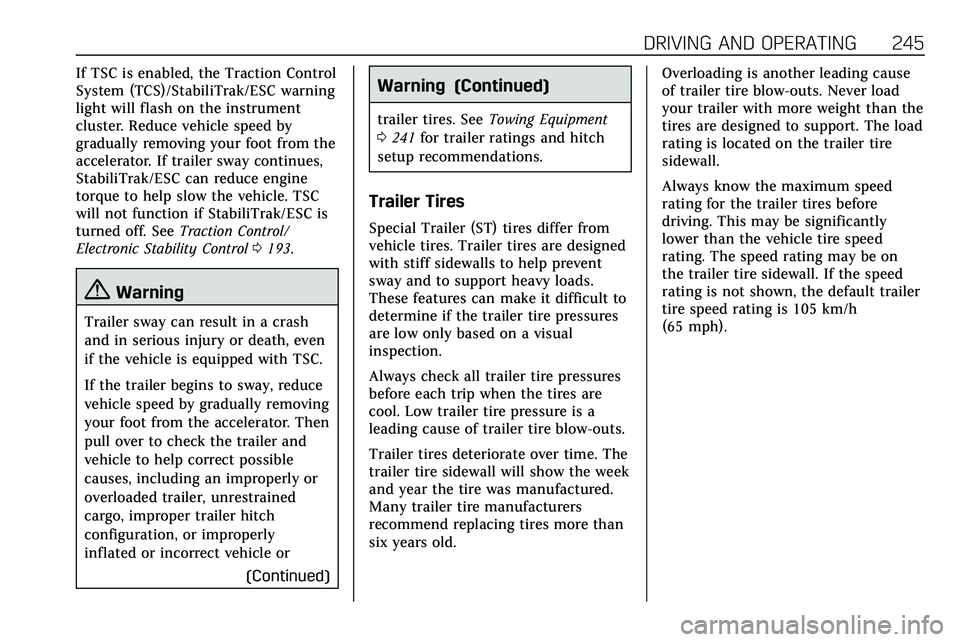
If TSC is enabled, the Traction Control
System (TCS)/StabiliTrak/ESC warning
light will flash on the instrument
cluster. Reduce vehicle speed by
gradually removing your foot from the
accelerator. If trailer sway continues,
StabiliTrak/ESC can reduce engine
torque to help slow the vehicle. TSC
will not function if StabiliTrak/ESC is
turned off. SeeTraction Control/
Electronic Stability Control 0193.
{Warning
Trailer sway can result in a crash
and in serious injury or death, even
if the vehicle is equipped with TSC.
If the trailer begins to sway, reduce
vehicle speed by gradually removing
your foot from the accelerator. Then
pull over to check the trailer and
vehicle to help correct possible
causes, including an improperly or
overloaded trailer, unrestrained
cargo, improper trailer hitch
configuration, or improperly
inflated or incorrect vehicle or
(Continued)
Warning (Continued)
trailer tires. SeeTowing Equipment
0 241 for trailer ratings and hitch
setup recommendations.
Trailer Tires
Special Trailer (ST) tires differ from
vehicle tires. Trailer tires are designed
with stiff sidewalls to help prevent
sway and to support heavy loads.
These features can make it difficult to
determine if the trailer tire pressures
are low only based on a visual
inspection.
Always check all trailer tire pressures
before each trip when the tires are
cool. Low trailer tire pressure is a
leading cause of trailer tire blow-outs.
Trailer tires deteriorate over time. The
trailer tire sidewall will show the week
and year the tire was manufactured.
Many trailer tire manufacturers
recommend replacing tires more than
six years old. Overloading is another leading cause
of trailer tire blow-outs. Never load
your trailer with more weight than the
tires are designed to support. The load
rating is located on the trailer tire
sidewall.
Always know the maximum speed
rating for the trailer tires before
driving. This may be significantly
lower than the vehicle tire speed
rating. The speed rating may be on
the trailer tire sidewall. If the speed
rating is not shown, the default trailer
tire speed rating is 105 km/h
(65 mph).
Page 247 of 384

246 DRIVING AND OPERATING
Conversions and
Add-Ons
Add-On Electrical
Equipment
{Warning
The Data Link Connector (DLC) is
used for vehicle service and
Emission Inspection/Maintenance
testing. SeeMalfunction Indicator
Lamp (Check Engine Light) 0115.
A device connected to the DLC —
such as an aftermarket fleet or
driver-behavior tracking device —
may interfere with vehicle systems.
This could affect vehicle operation
and cause a crash. Such devices
may also access information stored
in the vehicle’s systems.
Caution
Some electrical equipment can
damage the vehicle or cause
components to not work and would
not be covered by the vehicle
warranty. Always check with your
dealer before adding electrical
equipment.
Add-on equipment can drain the
vehicle's 12-volt battery, even if the
vehicle is not operating.
The vehicle has an airbag system.
Before attempting to add anything
electrical to the vehicle, see Servicing
the Airbag-Equipped Vehicle 071 and
Adding Equipment to the
Airbag-Equipped Vehicle 071.
Page 248 of 384

VEHICLE CARE 247
Vehicle Care
General Information
General Information . . . . . . . . . . . . . 248
California Proposition65 Warning . . . . . . . . . . . . . . . . . . . . . 248
California Perchlorate Materials Requirements . . . . . . . . . . . . . . . . . . . 249
Accessories and Modifications . . . . . . . . . . . . . . . . . . . 249
Vehicle Checks
Doing Your OwnService Work . . . . . . . . . . . . . . . . . . . . 249
Hood . . . . . . . . . . . . . . . . . . . . . . . . . . . . . . 250
Engine Compartment Overview . . . . . . . . . . . . . . . . . . . . . . . . . 252
Engine Oil . . . . . . . . . . . . . . . . . . . . . . . . . 255
Engine Oil Life System . . . . . . . . . . . 257
Automatic Transmission Fluid . . . . . . . . . . . . . . . . . . . . . . . . . . . . . 258
Engine Air Filter Life System . . . . 259
Engine Air Cleaner/Filter . . . . . . . . . 259
Cooling System . . . . . . . . . . . . . . . . . . . 260
Engine Overheating . . . . . . . . . . . . . . 264
Washer Fluid . . . . . . . . . . . . . . . . . . . . . 266
Brakes . . . . . . . . . . . . . . . . . . . . . . . . . . . . . 266
Brake Fluid . . . . . . . . . . . . . . . . . . . . . . . 267
Battery - North America . . . . . . . . . 268 All-Wheel Drive . . . . . . . . . . . . . . . . . . 269
Starter Switch Check . . . . . . . . . . . . . 269
Park Brake and P (Park)
Mechanism Check . . . . . . . . . . . . . . 269
Wiper Blade Replacement . . . . . . . 270
Windshield Replacement . . . . . . . . 271
Gas Strut(s) . . . . . . . . . . . . . . . . . . . . . . . 271
Headlamp Aiming
Front Headlamp Aiming . . . . . . . . . 272
Bulb Replacement
Bulb Replacement . . . . . . . . . . . . . . . . 273
Halogen Bulbs . . . . . . . . . . . . . . . . . . . . 273
LED Lighting . . . . . . . . . . . . . . . . . . . . . 273
Electrical System
Electrical System Overload . . . . . . 273
Fuses and Circuit Breakers . . . . . . 274
Engine Compartment Fuse
Block . . . . . . . . . . . . . . . . . . . . . . . . . . . . 274
Instrument Panel Fuse Block . . . . 277
Rear Compartment Fuse Block . . . . . . . . . . . . . . . . . . . . . . . . . . . . 279
Wheels and Tires
Tires . . . . . . . . . . . . . . . . . . . . . . . . . . . . . . . 282
All-Season Tires . . . . . . . . . . . . . . . . . . 283
Winter Tires . . . . . . . . . . . . . . . . . . . . . . 283
Summer Tires . . . . . . . . . . . . . . . . . . . . 283
Tire Sidewall Labeling . . . . . . . . . . . 284
Tire Designations . . . . . . . . . . . . . . . . . 286 Tire Terminology and
Definitions . . . . . . . . . . . . . . . . . . . . . . 286
Tire Pressure . . . . . . . . . . . . . . . . . . . . . . 289
Tire Pressure for High-Speed Operation . . . . . . . . . . . . . . . . . . . . . . . . 290
Tire Pressure Monitor System . . . 291
Tire Pressure Monitor Operation . . . . . . . . . . . . . . . . . . . . . . . . 292
Tire Inspection . . . . . . . . . . . . . . . . . . . 295
Tire Rotation . . . . . . . . . . . . . . . . . . . . . 296
When It Is Time for New Tires . . . . . . . . . . . . . . . . . . . . . . . . . . . . . 297
Buying New Tires . . . . . . . . . . . . . . . . 297
Different Size Tires and Wheels . . . . . . . . . . . . . . . . . . . . . . . . . . 299
Uniform Tire Quality Grading . . . 299
Wheel Alignment and Tire Balance . . . . . . . . . . . . . . . . . . . . . . . . . . 300
Wheel Replacement . . . . . . . . . . . . . . 301
Tire Chains . . . . . . . . . . . . . . . . . . . . . . . 301
If a Tire Goes Flat . . . . . . . . . . . . . . . . 302
Tire Sealant and Compressor Kit . . . . . . . . . . . . . . . . . 304
Storing the Tire Sealant and Compressor Kit . . . . . . . . . . . . . . . . . 310
Tire Changing . . . . . . . . . . . . . . . . . . . . . 310
Compact Spare Tire . . . . . . . . . . . . . . 315
Jump Starting
Jump Starting - North America . . . . . . . . . . . . . . . . . . . . . . . . . 316
Page 249 of 384

248 VEHICLE CARE
Towing the Vehicle
Towing the Vehicle . . . . . . . . . . . . . . . 319
Recreational Vehicle Towing . . . . 320
Appearance Care
Exterior Care . . . . . . . . . . . . . . . . . . . . . . 323
Interior Care . . . . . . . . . . . . . . . . . . . . . . 327
Floor Mats . . . . . . . . . . . . . . . . . . . . . . . . 330
General Information
For service and parts needs, visit your
dealer. You will receive genuine GM
parts and GM-trained and supported
service people.
Genuine GM parts have one of these
marks:
California Proposition
65 Warning
{Warning
Most motor vehicles, including this
one, as well as many of its service
parts and fluids, contain and/or
emit chemicals known to the State
of California to cause cancer and
birth defects or other reproductive
harm. Engine exhaust, many parts
and systems, many fluids, and
some component wear by-products
contain and/or emit these
chemicals. For more information go
to www.P65Warnings.ca.gov/
passenger-vehicle.
See Battery - North America 0268 and
Jump Starting - North America 0316
and the back cover.
Page 250 of 384

VEHICLE CARE 249
California Perchlorate
Materials Requirements
Certain types of automotive
applications, such as airbag initiators,
seat belt pretensioners, and lithium
batteries contained in electronic keys,
may contain perchlorate materials.
Perchlorate Material–special
handling may apply. See
www.dtsc.ca.gov/hazardouswaste/
perchlorate.
Accessories and
Modifications
Adding non-dealer accessories or
making modifications to the vehicle
can affect vehicle performance and
safety, including such things as
airbags, braking, stability, ride and
handling, emissions systems,
aerodynamics, durability, and
electronic systems like antilock
brakes, traction control, and stability
control. These accessories or
modifications could even cause
malfunction or damage not covered by
the vehicle warranty. Damage to suspension components
caused by modifying vehicle height
outside of factory settings will not be
covered by the vehicle warranty.
Damage to vehicle components
resulting from modifications or the
installation or use of non-GM certified
parts, including control module or
software modifications, is not covered
under the terms of the vehicle
warranty and may affect remaining
warranty coverage for affected parts.
GM Accessories are designed to
complement and function with other
systems on the vehicle. See your
dealer to accessorize the vehicle using
genuine GM Accessories installed by a
dealer technician.
Also, see
Adding Equipment to the
Airbag-Equipped Vehicle 071.
Vehicle Checks
Doing Your Own
Service Work
{Warning
It can be dangerous to work on
your vehicle if you do not have the
proper knowledge, service manual,
tools, or parts. Always follow
owner’s manual procedures and
consult the service manual for your
vehicle before doing any
service work.
If doing some of your own service
work, use the proper service manual.
It tells you much more about how to
service the vehicle than this manual
can. To order the proper service
manual, see Publication Ordering
Information 0358.
This vehicle has an airbag system.
Before attempting to do your own
service work, see Servicing the
Airbag-Equipped Vehicle 071.