ECO mode CADILLAC XT5 2020 Owner's Manual
[x] Cancel search | Manufacturer: CADILLAC, Model Year: 2020, Model line: XT5, Model: CADILLAC XT5 2020Pages: 384, PDF Size: 6.52 MB
Page 3 of 384
2 INTRODUCTION
Introduction
The names, logos, emblems, slogans,
vehicle model names, and vehicle
body designs appearing in this manual
including, but not limited to, GM, the
GM logo, CADILLAC, the CADILLAC
Emblem, and XT5are trademarks and/
or service marks of General Motors
LLC, its subsidiaries, affiliates,
or licensors.
For vehicles first sold in Canada,
substitute the name “General Motors
of Canada Company ”for Cadillac
Motor Car Division wherever it
appears in this manual. This manual describes features that
may or may not be on the vehicle
because of optional equipment that
was not purchased on the vehicle,
model variants, country specifications,
features/applications that may not be
available in your region, or changes
subsequent to the printing of this
owner’s manual.
Refer to the purchase documentation
relating to your specific vehicle to
confirm the features.
Keep this manual in the vehicle for
quick reference.
Canadian Vehicle Owners
A French language manual can be
obtained from your dealer, at
www.helminc.com, or from:
Propriétaires Canadiens
On peut obtenir un exemplaire de ce
guide en français auprès du
concessionnaire ou à l'adresse
suivante:Helm, Incorporated
Attention: Customer Service
47911 Halyard Drive
Plymouth, MI 48170
USA
Using this Manual
To quickly locate information about
the vehicle, use the Index in the back
of the manual. It is an alphabetical
list of what is in the manual and the
page number where it can be found.
Danger, Warning, and
Caution
Warning messages found on vehicle
labels and in this manual describe
hazards and what to do to avoid or
reduce them.
{Danger
Danger indicates a hazard with a
high level of risk which will result
in serious injury or death.
Litho in U.S.A.
Part No. 84290261 B Second Printing©2019 General Motors LLC. All Rights Reserved.
Page 15 of 384
14 KEYS, DOORS, AND WINDOWS
driver door and turn the key
counterclockwise, to the unlock
position, five times within
10 seconds.
The DIC displays READY FOR
REMOTE #2, 3, 4, ETC.
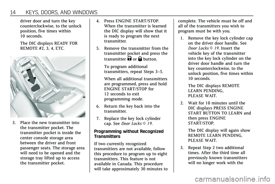
3. Place the new transmitter intothe transmitter pocket. The
transmitter pocket is inside the
center console storage area
between the driver and front
passenger seats. The storage area
will need to be opened and the
storage tray lifted up to access
the transmitter pocket. 4. Press ENGINE START/STOP.
When the transmitter is learned
the DIC display will show that it
is ready to program the next
transmitter.
5. Remove the transmitter from the transmitter pocket and press the
transmitter
KorQbutton.
To program additional
transmitters, repeat Steps 3–5.
When all additional transmitters
are programmed, press and hold
ENGINE START/STOP for
12 seconds to exit
programming mode.
6. Return the key back into the transmitter.
7. Replace the key lock cylinder cap. See Door Locks 019.
Programming without Recognized
Transmitters
If two currently recognized
transmitters are not available, follow
this procedure to program up to eight
transmitters. This feature is not
available in Canada. This procedure
will take approximately 30 minutes to complete. The vehicle must be off and
all of the transmitters you wish to
program must be with you.
1. Remove the key lock cylinder cap on the driver door handle. See
Door Locks 019. Insert the
vehicle key of the transmitter
into the key lock cylinder on the
driver door handle and turn the
key counterclockwise, to the
unlock position, five times within
10 seconds.
The DIC displays REMOTE
LEARN PENDING,
PLEASE WAIT.
2. Wait for 10 minutes until the DIC displays PRESS ENGINE
START BUTTON TO LEARN and
then press ENGINE
START/STOP.
The DIC display will again show
REMOTE LEARN PENDING,
PLEASE WAIT.
3. Repeat Step 2 two additional times. After the third time all
previously known transmitters
will no longer work with the
Page 16 of 384
KEYS, DOORS, AND WINDOWS 15
vehicle. Remaining transmitters
can be relearned during the next
steps.
The DIC display should now
show READY FOR REMOTE # 1.
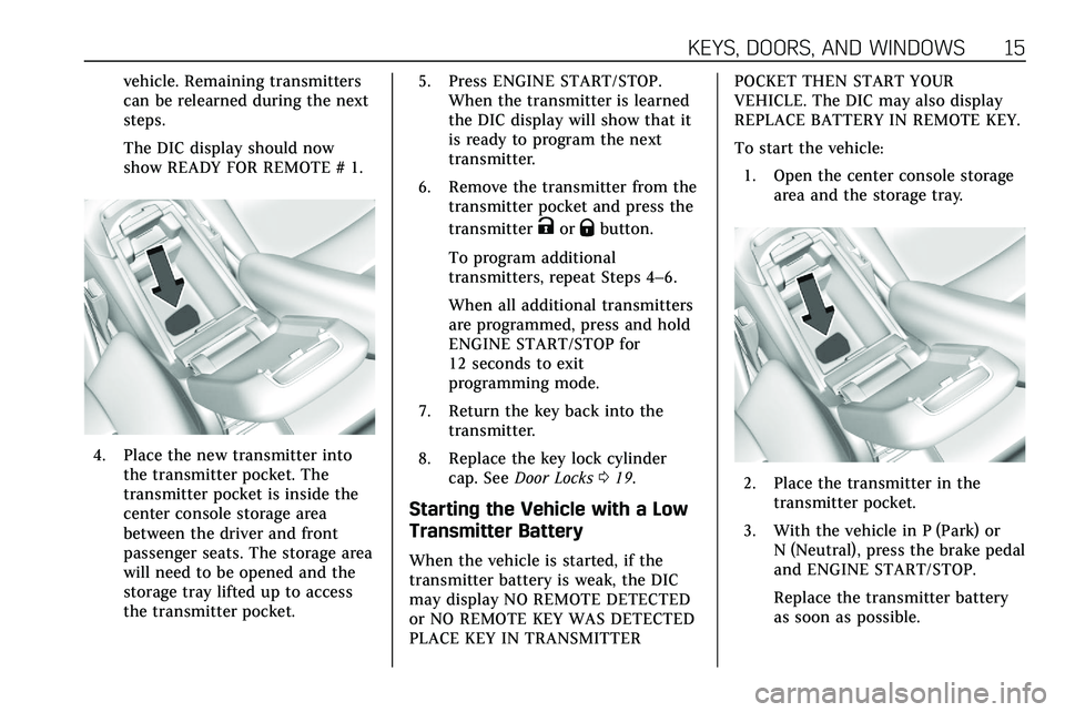
4. Place the new transmitter intothe transmitter pocket. The
transmitter pocket is inside the
center console storage area
between the driver and front
passenger seats. The storage area
will need to be opened and the
storage tray lifted up to access
the transmitter pocket. 5. Press ENGINE START/STOP.
When the transmitter is learned
the DIC display will show that it
is ready to program the next
transmitter.
6. Remove the transmitter from the transmitter pocket and press the
transmitter
KorQbutton.
To program additional
transmitters, repeat Steps 4–6.
When all additional transmitters
are programmed, press and hold
ENGINE START/STOP for
12 seconds to exit
programming mode.
7. Return the key back into the transmitter.
8. Replace the key lock cylinder cap. See Door Locks 019.
Starting the Vehicle with a Low
Transmitter Battery
When the vehicle is started, if the
transmitter battery is weak, the DIC
may display NO REMOTE DETECTED
or NO REMOTE KEY WAS DETECTED
PLACE KEY IN TRANSMITTER POCKET THEN START YOUR
VEHICLE. The DIC may also display
REPLACE BATTERY IN REMOTE KEY.
To start the vehicle:
1. Open the center console storage area and the storage tray.
2. Place the transmitter in thetransmitter pocket.
3. With the vehicle in P (Park) or N (Neutral), press the brake pedal
and ENGINE START/STOP.
Replace the transmitter battery
as soon as possible.
Page 27 of 384
26 KEYS, DOORS, AND WINDOWS
liftgate will reverse direction and open
fully. The liftgate will remain open
until it is activated again or closed
manually.
Setting the 3/4 Mode
To change the position the liftgate
stops at when opening:1. Select MAX or 3/4 mode and power open the liftgate.
2. Stop the liftgate movement at the desired height by pressing
any liftgate button. Manually
adjust the liftgate position if
needed.
3. Press and hold
lnext to the
pull cup on the outside of the
liftgate until the turn signals
flash and a beep sounds. This
indicates the setting has been
recorded.
The liftgate cannot be set below a
minimum programmable height.
If there is no light flash or sound,
then the height adjustment may be
too low.
Manual Operation
Select OFF to manually operate the
liftgate.
Caution
Attempting to move the liftgate too
quickly and with excessive force
may result in damage to the
vehicle.
Operate the liftgate manually with a
smooth motion and moderate speed.
The system includes a feature which
limits the manual closing speed to
protect the components.
To unlock the liftgate, press
Kon the
power door lock switch or press
Kon
the Remote Keyless Entry (RKE)
transmitter twice within five seconds.
See Remote Keyless Entry (RKE) System
Operation 010.
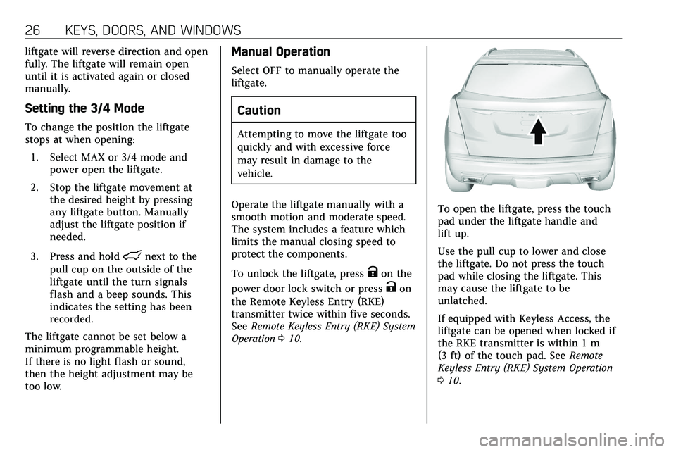
To open the liftgate, press the touch
pad under the liftgate handle and
lift up.
Use the pull cup to lower and close
the liftgate. Do not press the touch
pad while closing the liftgate. This
may cause the liftgate to be
unlatched.
If equipped with Keyless Access, the
liftgate can be opened when locked if
the RKE transmitter is within 1 m
(3 ft) of the touch pad. See Remote
Keyless Entry (RKE) System Operation
0 10.
Page 28 of 384
KEYS, DOORS, AND WINDOWS 27
The liftgate has an electric latch.
If the battery is disconnected or has
low voltage, the liftgate will not open.
The liftgate will resume operation
when the battery is reconnected and
charged.
Always close the liftgate before
driving.
Hands-Free Operation
If equipped, the liftgate may be
operated with a kicking motion under
the left side of the rear bumper.
The RKE transmitter must be within
1 m (3 ft) of the rear bumper to
operate the power liftgate hands-free.
The hands-free feature will not work
while the liftgate is moving. To stop
the liftgate while in motion use one of
the liftgate switches.
The hands-free feature can be
customized. SeeVehicle Personalization
0 131. Choose from the following:
On-Open and Close : The kicking
motion is activated to both open and
close the liftgate.
On-Open Only : The kicking motion is
activated to only open the liftgate. Off :
The feature is disabled.
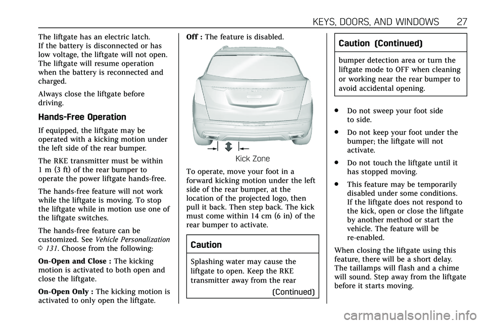
Kick Zone
To operate, move your foot in a
forward kicking motion under the left
side of the rear bumper, at the
location of the projected logo, then
pull it back. Then step back. The kick
must come within 14 cm (6 in) of the
rear bumper to activate.
Caution
Splashing water may cause the
liftgate to open. Keep the RKE
transmitter away from the rear (Continued)
Caution (Continued)
bumper detection area or turn the
liftgate mode to OFF when cleaning
or working near the rear bumper to
avoid accidental opening.
. Do not sweep your foot side
to side.
. Do not keep your foot under the
bumper; the liftgate will not
activate.
. Do not touch the liftgate until it
has stopped moving.
. This feature may be temporarily
disabled under some conditions.
If the liftgate does not respond to
the kick, open or close the liftgate
by another method or start the
vehicle. The feature will be
re-enabled.
When closing the liftgate using this
feature, there will be a short delay.
The taillamps will flash and a chime
will sound. Step away from the liftgate
before it starts moving.
Page 33 of 384
32 KEYS, DOORS, AND WINDOWS
.A message to service the steering
column lock indicates that an
issue has been detected with the
column lock feature and the
vehicle should be serviced.
. A message that the steering
column is locked indicates that
the engine is running, but the
steering column is still locked. It is
normal for the column to be
locked during a remote start, but
the column should unlock after
the brake pedal is pressed and the
vehicle is started. No message will
display during a remote start.
. A message that the steering wheel
must be turned and the vehicle
must be started again indicates
that the column lock mechanism
is bound, the column locking
device was unable to unlock the
steering column, and the vehicle
did not start. If this happens,
immediately turn the steering
wheel from side to side to unbind
the column lock. If this does not
unlock the steering column, turn
the vehicle off and open the driver
door to reset the system. Then turn the vehicle on and
immediately turn the steering
wheel side to side for about
15 seconds. In some cases, it may
take significant force to unbind
the column.
To keep the steering column from
binding, straighten the front wheels
before turning off the vehicle.
Immobilizer
See Radio Frequency Statement 0358.
Immobilizer Operation
This vehicle has a passive
theft-deterrent system.
The system does not have to be
manually armed or disarmed.
The vehicle is automatically
immobilized when the vehicle is
turned off.
The immobilization system is
disarmed when the ignition is on or in
ACC/ACCESSORY and a valid
transmitter is present in the vehicle.
The security light, in the instrument
cluster, comes on if there is a problem
with arming or disarming the
theft-deterrent system.
The system has one or more RKE
transmitters matched to an
immobilizer control unit in your
vehicle. Only a correctly matched RKE
transmitter will start the vehicle.
If the transmitter is ever damaged,
you may not be able to start your
vehicle.
When trying to start the vehicle, the
security light may come on briefly
when the ignition is turned on.
If the engine does not start and the
security light stays on, there is a
problem with the system. Turn the
ignition off and try again.
If the vehicle will not change ignition
modes (ACC/ACCESSORY, on, off), and
the RKE transmitter appears to be
Page 60 of 384
SEATS AND RESTRAINTS 59
After the height adjuster is set to the
desired position, try to move it down
without pressing the release button to
make sure it has locked into position.
Automatic Seat Belt Tightening
System
The vehicle may have the Automatic
Seat Belt Tightening System.
Each time the front seat belts are
buckled while the vehicle is in P (Park)
or D (Drive) and the engine is running
or in Auto Stop (if equipped), the
system may activate to tighten the
seat belts.
The system also activates during
emergency braking and/or sudden
driving maneuvers and releases when
driving conditions return to normal.
The system will not activate if the
Traction Control/Electronic Stability
Control system is not functioning
properly. SeeTraction Control/
Electronic Stability Control 0193.
If there is a problem with the
Automatic Seat Belt Tightening
System, a message displays on the
Driver Information Center (DIC). If a
system unavailable message displays repeatedly or if a service message
displays, see your dealer. Other seat
belt functions are not affected by the
Automatic Seat Belt Tightening
System.
Seat Belt Pretensioners
This vehicle has seat belt
pretensioners for the front outboard
occupants. Although the seat belt
pretensioners cannot be seen, they are
part of the seat belt assembly. They
can help tighten the seat belts during
the early stages of a moderate to
severe frontal, near frontal, or rear
crash if the threshold conditions for
pretensioner activation are met. Seat
belt pretensioners can also help
tighten the seat belts in a side crash
or a rollover event.
Pretensioners work only once. If the
pretensioners activate in a crash, the
pretensioners and probably other
parts of the vehicle’s seat belt system
will need to be replaced. See
Replacing
Seat Belt System Parts after a Crash
0 61. Do not sit on the outboard seat belt
while entering or exiting the vehicle or
at any time while sitting in the seat.
Sitting on the seat belt can damage
the webbing and hardware.
Rear Seat Belt Comfort Guides
Rear seat belt comfort guides may
provide added seat belt comfort for
older children who have outgrown
booster seats and for some adults.
When installed on a shoulder belt, the
comfort guide positions the shoulder
belt away from the neck and head.
Comfort guides for the second row
outboard seating positions may be
provided in a package in the glovebox
or cargo area, or they are available
through your dealer. Instructions are
included with the guides.
Seat Belt Use During
Pregnancy
Seat belts work for everyone,
including pregnant women. Like all
occupants, they are more likely to be
seriously injured if they do not wear
seat belts.
Page 65 of 384

64 SEATS AND RESTRAINTS
Driver Side Shown, Passenger SideSimilar
The seat-mounted side impact airbags
for the driver and front outboard
passenger are in the sides of the
seatbacks closest to the door.
The roof-rail airbags for the driver,
front outboard passenger, and second
row outboard passengers are in the
ceiling above the side windows.
{Warning
If something is between an
occupant and an airbag, the airbag
might not inflate properly or it
might force the object into that
person causing severe injury or
even death. The path of an inflating
airbag must be kept clear. Do not
put anything between an occupant
and an airbag, and do not attach or
put anything on the steering wheel
hub or on or near any other airbag
covering.
Do not use seat accessories that
block the inflation path of a
seat-mounted side impact airbag.
Never secure anything to the roof of
a vehicle with roof-rail airbags by
routing a rope or tie‐down through
any door or window opening. If you
do, the path of an inflating roof-rail
airbag will be blocked.
When Should an Airbag
Inflate?
This vehicle is equipped with airbags.
See Airbag System 061. Airbags are
designed to inflate if the impact
exceeds the specific airbag system's
deployment threshold. Deployment
thresholds are used to predict how
severe a crash is likely to be in time
for the airbags to inflate and help
restrain the occupants. The vehicle
has electronic sensors that help the
airbag system determine the severity
of the impact. Deployment thresholds
can vary with specific vehicle design.
Frontal airbags are designed to inflate
in moderate to severe frontal or near
frontal crashes to help reduce the
potential for severe injuries, mainly to
the driver's or front outboard
passenger's head and chest.
Whether the frontal airbags will or
should inflate is not based primarily
on how fast the vehicle is traveling.
It depends on what is hit, the
direction of the impact, and how
quickly the vehicle slows down.
Page 66 of 384

SEATS AND RESTRAINTS 65
Frontal airbags may inflate at
different crash speeds depending on
whether the vehicle hits an object
straight on or at an angle, and
whether the object is fixed or moving,
rigid or deformable, narrow or wide.
Frontal airbags are not intended to
inflate during vehicle rollovers, in rear
impacts, or in many side impacts.
In addition, the vehicle has advanced
technology frontal airbags. Advanced
technology frontal airbags adjust the
restraint according to either crash
severity or occupant interaction.
Knee airbags are designed to inflate in
moderate to severe frontal or near
frontal impacts. Knee airbags are not
designed to inflate during vehicle
rollovers, in rear impacts, or in many
side impacts.
Seat-mounted side impact airbags are
designed to inflate in moderate to
severe side crashes, depending on the
location of the impact. These airbags
are also designed to inflate in some
moderate to severe frontal or
near-frontal impacts that could result
in the occupant moving toward the
side of the vehicle. Seat-mounted sideimpact airbags are not designed to
inflate in rollovers, or rear impacts.
A seat-mounted side impact airbag is
designed to inflate on the side of the
vehicle that is struck.
Roof-rail airbags are designed to
inflate in moderate to severe side
crashes depending on the location of
the impact. In addition, these roof-rail
airbags are designed to inflate during
a rollover or in a severe frontal
impact. Roof-rail airbags are not
designed to inflate in rear impacts.
Both roof-rail airbags will inflate when
either side of the vehicle is struck,
if the sensing system predicts that the
vehicle is about to roll over on its
side, or in a severe frontal impact.
In any particular crash, no one can
say whether an airbag should have
inflated simply because of the vehicle
damage or repair costs.
What Makes an Airbag
Inflate?
In a deployment event, the sensing
system sends an electrical signal
triggering a release of gas from the
inflator. Gas from the inflator fills the
airbag causing the bag to break out of
the cover. The inflator, the airbag, and
related hardware are all part of the
airbag module.
For airbag locations, see
Where Are the
Airbags? 063.
How Does an Airbag
Restrain?
In moderate to severe frontal or near
frontal collisions, even belted
occupants can contact the steering
wheel or the instrument panel. In
moderate to severe side collisions,
even belted occupants can contact the
inside of the vehicle.
Airbags supplement the protection
provided by seat belts by distributing
the force of the impact more evenly
over the occupant's body.
Rollover capable roof-rail airbags are
designed to help contain the head and
chest of occupants in the outboard
seating positions in the first and
second rows. The rollover capable
roof-rail airbags are designed to help
reduce the risk of full or partial
Page 116 of 384
INSTRUMENTS AND CONTROLS 115
If the word ON, or the on symbol, is
lit on the passenger airbag status
indicator, it means that the front
outboard passenger frontal airbag is
allowed to inflate.
If the word OFF, or the off symbol, is
lit on the passenger airbag status
indicator, it means that the passenger
sensing system has turned off the
front outboard passenger frontal
airbag.
If, after several seconds, both status
indicator lights remain on, or if there
are no lights at all, there may be a
problem with the lights or the
passenger sensing system. See your
dealer for service.
{Warning
If the airbag readiness light ever
comes on and stays on, it means
that something may be wrong with
the airbag system. To help avoid
injury to yourself or others, have(Continued)
Warning (Continued)
the vehicle serviced right away. See
Airbag Readiness Light0114 for
more information, including
important safety information.
Charging System Light
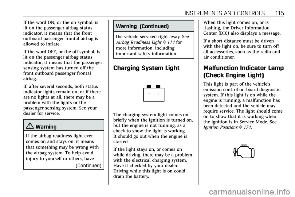
The charging system light comes on
briefly when the ignition is turned on,
but the engine is not running, as a
check to show the light is working.
It should go out when the engine is
started.
If the light stays on, or comes on
while driving, there may be a problem
with the electrical charging system.
Have it checked by your dealer.
Driving while this light is on could
drain the battery. When this light comes on, or is
flashing, the Driver Information
Center (DIC) also displays a message.
If a short distance must be driven
with the light on, be sure to turn off
all accessories, such as the radio and
air conditioner.
Malfunction Indicator Lamp
(Check Engine Light)
This light is part of the vehicle’s
emission control on-board diagnostic
system. If this light is on while the
engine is running, a malfunction has
been detected and the vehicle may
require service. The light should come
on to show that it is working when
the ignition is in Service Mode. See
Ignition Positions
0174.