fuse CADILLAC XT5 2020 Owner's Manual
[x] Cancel search | Manufacturer: CADILLAC, Model Year: 2020, Model line: XT5, Model: CADILLAC XT5 2020Pages: 384, PDF Size: 6.52 MB
Page 4 of 384
INTRODUCTION 3
{Warning
Warning indicates a hazard that
could result in injury or death.
Caution
Caution indicates a hazard that
could result in property or vehicle
damage.
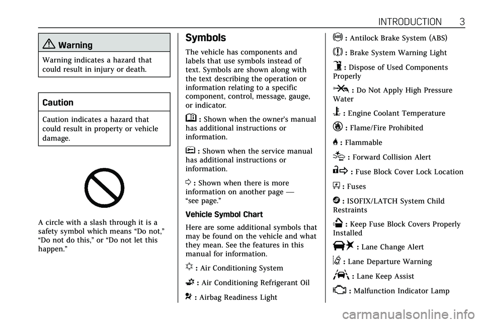
A circle with a slash through it is a
safety symbol which means“Do not,”
“Do not do this,” or“Do not let this
happen.”
Symbols
The vehicle has components and
labels that use symbols instead of
text. Symbols are shown along with
the text describing the operation or
information relating to a specific
component, control, message, gauge,
or indicator.
M: Shown when the owner’s manual
has additional instructions or
information.
*: Shown when the service manual
has additional instructions or
information.
0: Shown when there is more
information on another page —
“see page.”
Vehicle Symbol Chart
Here are some additional symbols that
may be found on the vehicle and what
they mean. See the features in this
manual for information.
u: Air Conditioning System
G:Air Conditioning Refrigerant Oil
9:Airbag Readiness Light
!:Antilock Brake System (ABS)
$:Brake System Warning Light
9:Dispose of Used Components
Properly
P: Do Not Apply High Pressure
Water
B: Engine Coolant Temperature
_:Flame/Fire Prohibited
H: Flammable
[:Forward Collision Alert
R:Fuse Block Cover Lock Location
+:Fuses
j:ISOFIX/LATCH System Child
Restraints
Q: Keep Fuse Block Covers Properly
Installed
|: Lane Change Alert
@:Lane Departure Warning
A:Lane Keep Assist
*: Malfunction Indicator Lamp
Page 106 of 384
INSTRUMENTS AND CONTROLS 105
Lift the cover to access the accessory
power outlet.
Certain accessory power plugs may
not be compatible with the accessory
power outlet and could overload
vehicle or adapter fuses. If a problem
is experienced, see your dealer.
When adding electrical equipment, be
sure to follow the proper installation
instructions included with the
equipment. SeeAdd-On Electrical
Equipment 0246.
Caution
Hanging heavy equipment from the
power outlet can cause damage not
covered by the vehicle warranty.
The power outlets are designed for
accessory power plugs only, such as
cell phone charge cords.
Always unplug electrical equipment
when not in use and do not plug in
equipment that exceeds the maximum
15 amps rating.
Wireless Charging
The vehicle may have wireless
charging in the storage under the
armrest. The system operates at 145
kHz and wirelessly charges one Qi
compatible smartphone. The power
output of the system is capable of
charging at a rate up to 3 amp (15W),
as requested by the compatible
smartphone. See Radio Frequency
Statement 0358.
{Warning
Wireless charging can affect the
operation of an implanted
pacemaker or other medical devices.
If you have one, it is recommended
to consult with your doctor before
using the wireless charging system.
The vehicle must be on, in ACC/
ACCESSORY, or Retained Accessory
Power (RAP) must be active. The
wireless charging feature may not
correctly indicate charging when the
vehicle is in RAP. See Retained
Accessory Power (RAP) 0180. The operating temperature is
−20 °C
(−4 °F) to 60 °C (140 °F) for the
charging system and 0 °C (32 °F) to
35 °C (95 °F) for the smartphone.
{Warning
Remove all objects from the
charging pocket before charging
your compatible smartphone.
Objects, such as coins, keys, rings,
paper clips, or cards, between the
smartphone and the charger will
become very hot. On the rare
occasion that the charging system
does not detect an object, and the
object gets wedged between the
smartphone and the charger,
remove the smartphone and allow
the object to cool before removing
it from the charging pocket, to
prevent burns.
Page 145 of 384
144 LIGHTING
If after signaling a turn or lane
change, the arrow flashes rapidly or
does not come on, a signal bulb may
be burned out.
Replace any burned out bulbs. If a
bulb is not burned out, check the fuse.
SeeFuses and Circuit Breakers 0274.
Cornering Lamps
Cornering lamps automatically come
on when all of the following occur:
.
The low-beam headlamps are on.
. The turn signals are activated or
the steering wheel is at a turning
angle.
. The vehicle speed is below
40 km/h (25 mph).
Interior Lighting
Instrument Panel
Illumination Control
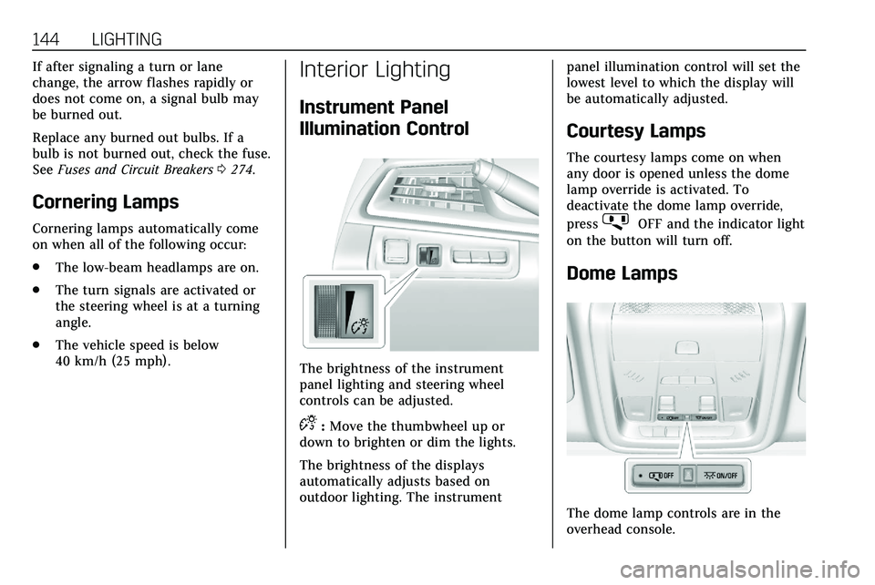
The brightness of the instrument
panel lighting and steering wheel
controls can be adjusted.
D:Move the thumbwheel up or
down to brighten or dim the lights.
The brightness of the displays
automatically adjusts based on
outdoor lighting. The instrument panel illumination control will set the
lowest level to which the display will
be automatically adjusted.
Courtesy Lamps
The courtesy lamps come on when
any door is opened unless the dome
lamp override is activated. To
deactivate the dome lamp override,
press
jOFF and the indicator light
on the button will turn off.
Dome Lamps
The dome lamp controls are in the
overhead console.
Page 245 of 384
244 DRIVING AND OPERATING
Tail/Parking
LampsGray/Brown
Reverse Lamps White/Green
Battery Feed Red/Green
Ground Black
Electric Trailer
Brake* Blue
* Circuit powered by electric trailer
brake control wiring provisions.
Electric Trailer Brake Control
Wiring Provisions
Wiring provisions for an aftermarket
electric trailer brake controller are
included with the vehicle as part of
the trailer wiring package. The
harness contains the following
circuits: Electric Trailer
Brakes Blue
Battery Feed Red/Green or
Red/Blue
Brake Apply
Signal White/Blue
Ground Black Refer to the aftermarket electric trailer
brake controller owner's manual to
determine wire color coding of the
electric trailer brake controller. The
wire colors on the brake controller
may be different from the vehicle. The
electric trailer brake controller should
be installed by your dealer or a
qualified service center.
If equipped, there are four blunt cut
wires inside the front driver side
instrument panel. It will be necessary
to have a technician connect the
12-volt power to the engine
compartment fuse block.Trailer Lamps
Always check all trailer lamps are
working at the beginning of each trip,
and periodically on longer trips.
Turn Signals When Towing a
Trailer
When properly connected, the trailer
turn signals will illuminate to indicate
the vehicle is turning, changing lanes,
or stopping. When towing a trailer,
the arrows on the instrument cluster
will illuminate even if the trailer is not
properly connected or the bulbs are
burned out.
Always check all trailer lamps are
working at the beginning of each trip,
and periodically on longer trips.
Trailer Sway Control (TSC)
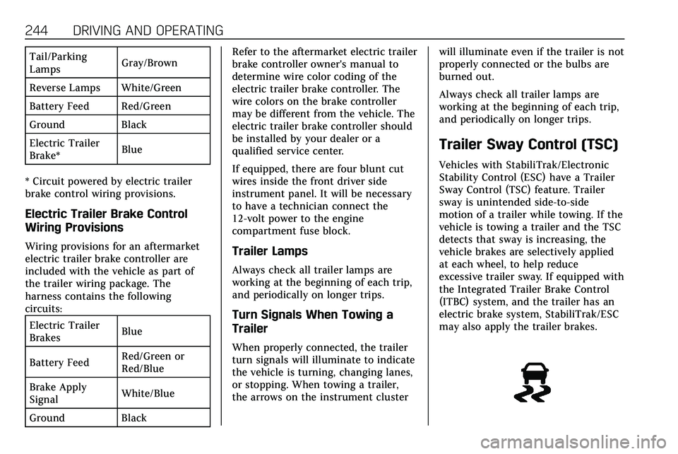
Vehicles with StabiliTrak/Electronic
Stability Control (ESC) have a Trailer
Sway Control (TSC) feature. Trailer
sway is unintended side-to-side
motion of a trailer while towing. If the
vehicle is towing a trailer and the TSC
detects that sway is increasing, the
vehicle brakes are selectively applied
at each wheel, to help reduce
excessive trailer sway. If equipped with
the Integrated Trailer Brake Control
(ITBC) system, and the trailer has an
electric brake system, StabiliTrak/ESC
may also apply the trailer brakes.
Page 248 of 384
VEHICLE CARE 247
Vehicle Care
General Information
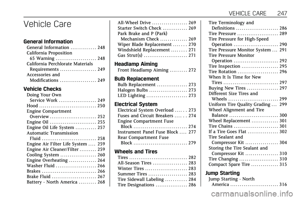
General Information . . . . . . . . . . . . . 248
California Proposition65 Warning . . . . . . . . . . . . . . . . . . . . . 248
California Perchlorate Materials Requirements . . . . . . . . . . . . . . . . . . . 249
Accessories and Modifications . . . . . . . . . . . . . . . . . . . 249
Vehicle Checks
Doing Your OwnService Work . . . . . . . . . . . . . . . . . . . . 249
Hood . . . . . . . . . . . . . . . . . . . . . . . . . . . . . . 250
Engine Compartment Overview . . . . . . . . . . . . . . . . . . . . . . . . . 252
Engine Oil . . . . . . . . . . . . . . . . . . . . . . . . . 255
Engine Oil Life System . . . . . . . . . . . 257
Automatic Transmission Fluid . . . . . . . . . . . . . . . . . . . . . . . . . . . . . 258
Engine Air Filter Life System . . . . 259
Engine Air Cleaner/Filter . . . . . . . . . 259
Cooling System . . . . . . . . . . . . . . . . . . . 260
Engine Overheating . . . . . . . . . . . . . . 264
Washer Fluid . . . . . . . . . . . . . . . . . . . . . 266
Brakes . . . . . . . . . . . . . . . . . . . . . . . . . . . . . 266
Brake Fluid . . . . . . . . . . . . . . . . . . . . . . . 267
Battery - North America . . . . . . . . . 268 All-Wheel Drive . . . . . . . . . . . . . . . . . . 269
Starter Switch Check . . . . . . . . . . . . . 269
Park Brake and P (Park)
Mechanism Check . . . . . . . . . . . . . . 269
Wiper Blade Replacement . . . . . . . 270
Windshield Replacement . . . . . . . . 271
Gas Strut(s) . . . . . . . . . . . . . . . . . . . . . . . 271
Headlamp Aiming
Front Headlamp Aiming . . . . . . . . . 272
Bulb Replacement
Bulb Replacement . . . . . . . . . . . . . . . . 273
Halogen Bulbs . . . . . . . . . . . . . . . . . . . . 273
LED Lighting . . . . . . . . . . . . . . . . . . . . . 273
Electrical System
Electrical System Overload . . . . . . 273
Fuses and Circuit Breakers . . . . . . 274
Engine Compartment Fuse
Block . . . . . . . . . . . . . . . . . . . . . . . . . . . . 274
Instrument Panel Fuse Block . . . . 277
Rear Compartment Fuse Block . . . . . . . . . . . . . . . . . . . . . . . . . . . . 279
Wheels and Tires
Tires . . . . . . . . . . . . . . . . . . . . . . . . . . . . . . . 282
All-Season Tires . . . . . . . . . . . . . . . . . . 283
Winter Tires . . . . . . . . . . . . . . . . . . . . . . 283
Summer Tires . . . . . . . . . . . . . . . . . . . . 283
Tire Sidewall Labeling . . . . . . . . . . . 284
Tire Designations . . . . . . . . . . . . . . . . . 286 Tire Terminology and
Definitions . . . . . . . . . . . . . . . . . . . . . . 286
Tire Pressure . . . . . . . . . . . . . . . . . . . . . . 289
Tire Pressure for High-Speed Operation . . . . . . . . . . . . . . . . . . . . . . . . 290
Tire Pressure Monitor System . . . 291
Tire Pressure Monitor Operation . . . . . . . . . . . . . . . . . . . . . . . . 292
Tire Inspection . . . . . . . . . . . . . . . . . . . 295
Tire Rotation . . . . . . . . . . . . . . . . . . . . . 296
When It Is Time for New Tires . . . . . . . . . . . . . . . . . . . . . . . . . . . . . 297
Buying New Tires . . . . . . . . . . . . . . . . 297
Different Size Tires and Wheels . . . . . . . . . . . . . . . . . . . . . . . . . . 299
Uniform Tire Quality Grading . . . 299
Wheel Alignment and Tire Balance . . . . . . . . . . . . . . . . . . . . . . . . . . 300
Wheel Replacement . . . . . . . . . . . . . . 301
Tire Chains . . . . . . . . . . . . . . . . . . . . . . . 301
If a Tire Goes Flat . . . . . . . . . . . . . . . . 302
Tire Sealant and Compressor Kit . . . . . . . . . . . . . . . . . 304
Storing the Tire Sealant and Compressor Kit . . . . . . . . . . . . . . . . . 310
Tire Changing . . . . . . . . . . . . . . . . . . . . . 310
Compact Spare Tire . . . . . . . . . . . . . . 315
Jump Starting
Jump Starting - North America . . . . . . . . . . . . . . . . . . . . . . . . . 316
Page 254 of 384
VEHICLE CARE 253
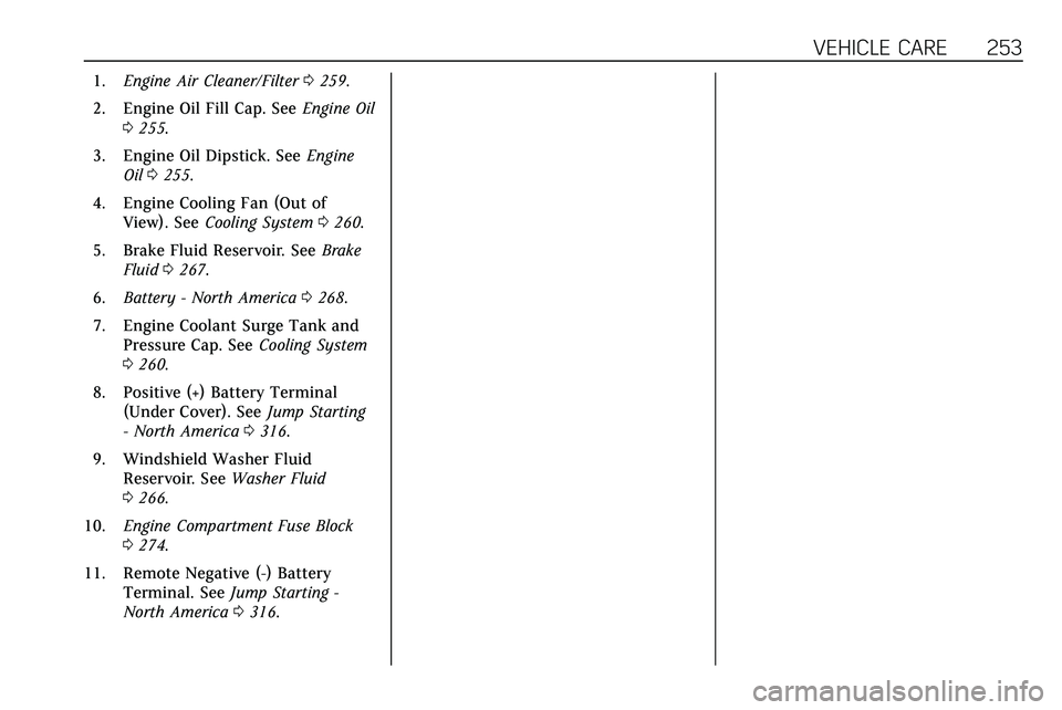
1.Engine Air Cleaner/Filter 0259.
2. Engine Oil Fill Cap. See Engine Oil
0 255.
3. Engine Oil Dipstick. See Engine
Oil 0255.
4. Engine Cooling Fan (Out of View). See Cooling System 0260.
5. Brake Fluid Reservoir. See Brake
Fluid 0267.
6. Battery - North America 0268.
7. Engine Coolant Surge Tank and Pressure Cap. See Cooling System
0 260.
8. Positive (+) Battery Terminal (Under Cover). See Jump Starting
- North America 0316.
9. Windshield Washer Fluid Reservoir. See Washer Fluid
0 266.
10. Engine Compartment Fuse Block
0274.
11. Remote Negative (-) Battery Terminal. See Jump Starting -
North America 0316.
Page 256 of 384
VEHICLE CARE 255
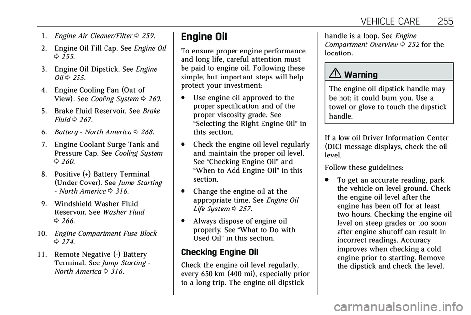
1.Engine Air Cleaner/Filter 0259.
2. Engine Oil Fill Cap. See Engine Oil
0 255.
3. Engine Oil Dipstick. See Engine
Oil 0255.
4. Engine Cooling Fan (Out of View). See Cooling System 0260.
5. Brake Fluid Reservoir. See Brake
Fluid 0267.
6. Battery - North America 0268.
7. Engine Coolant Surge Tank and Pressure Cap. See Cooling System
0 260.
8. Positive (+) Battery Terminal (Under Cover). See Jump Starting
- North America 0316.
9. Windshield Washer Fluid Reservoir. See Washer Fluid
0 266.
10. Engine Compartment Fuse Block
0274.
11. Remote Negative (-) Battery Terminal. See Jump Starting -
North America 0316.Engine Oil
To ensure proper engine performance
and long life, careful attention must
be paid to engine oil. Following these
simple, but important steps will help
protect your investment:
.
Use engine oil approved to the
proper specification and of the
proper viscosity grade. See
“Selecting the Right Engine Oil” in
this section.
. Check the engine oil level regularly
and maintain the proper oil level.
See “Checking Engine Oil” and
“When to Add Engine Oil” in this
section.
. Change the engine oil at the
appropriate time. See Engine Oil
Life System 0257.
. Always dispose of engine oil
properly. See “What to Do with
Used Oil” in this section.
Checking Engine Oil
Check the engine oil level regularly,
every 650 km (400 mi), especially prior
to a long trip. The engine oil dipstick handle is a loop. See
Engine
Compartment Overview 0252 for the
location.
{Warning
The engine oil dipstick handle may
be hot; it could burn you. Use a
towel or glove to touch the dipstick
handle.
If a low oil Driver Information Center
(DIC) message displays, check the oil
level.
Follow these guidelines:
. To get an accurate reading, park
the vehicle on level ground. Check
the engine oil level after the
engine has been off for at least
two hours. Checking the engine oil
level on steep grades or too soon
after engine shutoff can result in
incorrect readings. Accuracy
improves when checking a cold
engine prior to starting. Remove
the dipstick and check the level.
Page 274 of 384
VEHICLE CARE 273
Bulb Replacement
For the proper type of replacement
bulbs, or any bulb changing procedure
not listed in this section, contact your
dealer.
Caution
Do not replace incandescent bulbs
with aftermarket LED replacement
bulbs. This can cause damage to
the vehicle electrical system.
Halogen Bulbs
{Warning
Halogen bulbs have pressurized gas
inside and can burst if you drop or
scratch the bulb. You or others
could be injured. Be sure to read
and follow the instructions on the
bulb package.
LED Lighting
This vehicle has several LED lamps.
For replacement of any LED lighting
assembly, contact your dealer.
Electrical System
Electrical System Overload
The vehicle has fuses and circuit
breakers to protect against an
electrical system overload.
When the current electrical load is too
heavy, the circuit breaker opens and
closes, protecting the circuit until the
current load returns to normal or the
problem is fixed. This greatly reduces
the chance of circuit overload and fire
caused by electrical problems.
Fuses and circuit breakers protect
power devices in the vehicle.
Replace a bad fuse with a new one of
the identical size and rating.
If there is a problem on the road and
a fuse needs to be replaced, the
same amperage fuse can be borrowed.
Choose some feature of the vehicle
that is not needed to use and replace
it as soon as possible.
Page 275 of 384
274 VEHICLE CARE
Headlamp Wiring
An electrical overload may cause the
lamps to go on and off, or in some
cases to remain off. Have the
headlamp wiring checked right away if
the lamps go on and off or remain off.
Windshield Wipers
If the wiper motor overheats due to
heavy snow or ice, the windshield
wipers will stop until the motor cools
and will then restart.
Although the circuit is protected from
electrical overload, overload due to
heavy snow or ice may cause wiper
linkage damage. Always clear ice and
heavy snow from the windshield
before using the windshield wipers.
If the overload is caused by an
electrical problem and not snow or
ice, be sure to get it fixed.
Fuses and Circuit Breakers
The wiring circuits in the vehicle are
protected from short circuits by a
combination of fuses and circuitbreakers. This greatly reduces the
chance of damage caused by electrical
problems.
{Danger
Fuses and circuit breakers are
marked with their ampere rating.
Do not exceed the
specified amperage rating when
replacing fuses and circuit breakers.
Use of an oversized fuse or circuit
breaker can result in a vehicle fire.
You and others could be seriously
injured or killed.
To check a fuse, look at the
silver-colored band inside the fuse.
If the band is broken or melted,
replace the fuse. Be sure to replace a
bad fuse with a new one of the
identical size and rating.
Fuses of the same amperage can be
temporarily borrowed from another
fuse location, if a fuse goes out.
Replace the fuse as soon as possible.
Engine Compartment Fuse
Block
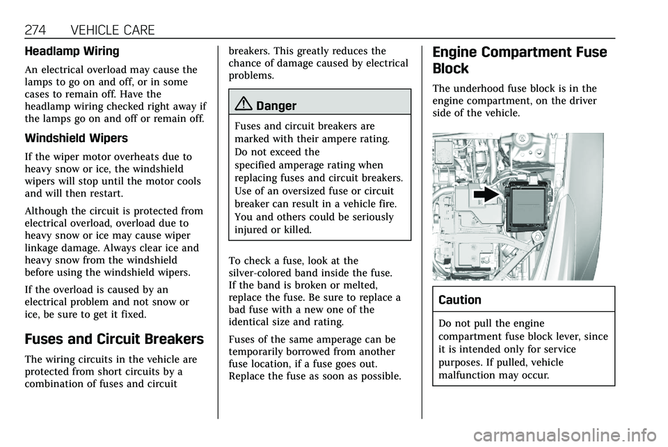
The underhood fuse block is in the
engine compartment, on the driver
side of the vehicle.
Caution
Do not pull the engine
compartment fuse block lever, since
it is intended only for service
purposes. If pulled, vehicle
malfunction may occur.
Page 276 of 384
VEHICLE CARE 275
Caution
Spilling liquid on any electrical
component on the vehicle may
damage it. Always keep the covers
on any electrical component.
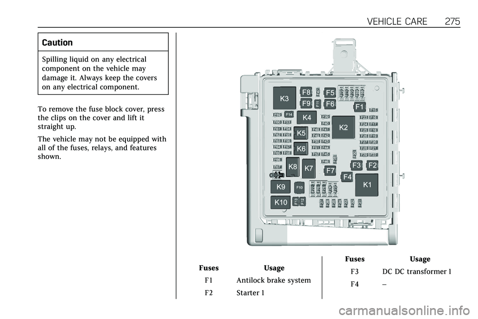
To remove the fuse block cover, press
the clips on the cover and lift it
straight up.
The vehicle may not be equipped with
all of the fuses, relays, and features
shown.
Fuses Usage
F1 Antilock brake system
F2 Starter 1 Fuses
Usage
F3 DC DC transformer 1
F4 –