radio CADILLAC XT5 2020 Owner's Manual
[x] Cancel search | Manufacturer: CADILLAC, Model Year: 2020, Model line: XT5, Model: CADILLAC XT5 2020Pages: 384, PDF Size: 6.52 MB
Page 11 of 384
10 KEYS, DOORS, AND WINDOWS
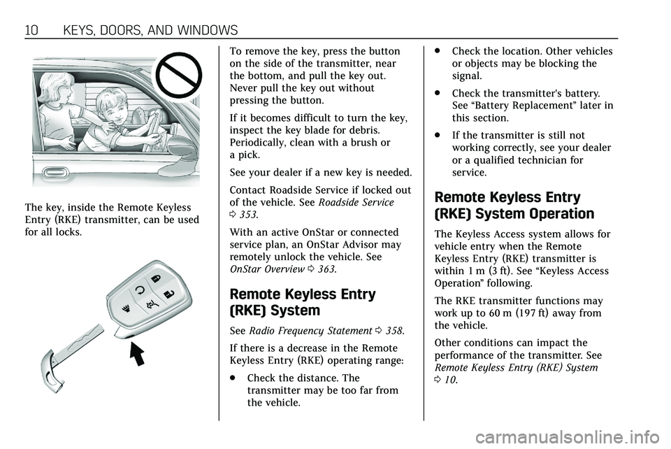
The key, inside the Remote Keyless
Entry (RKE) transmitter, can be used
for all locks.
To remove the key, press the button
on the side of the transmitter, near
the bottom, and pull the key out.
Never pull the key out without
pressing the button.
If it becomes difficult to turn the key,
inspect the key blade for debris.
Periodically, clean with a brush or
a pick.
See your dealer if a new key is needed.
Contact Roadside Service if locked out
of the vehicle. SeeRoadside Service
0 353.
With an active OnStar or connected
service plan, an OnStar Advisor may
remotely unlock the vehicle. See
OnStar Overview 0363.
Remote Keyless Entry
(RKE) System
See Radio Frequency Statement 0358.
If there is a decrease in the Remote
Keyless Entry (RKE) operating range:
. Check the distance. The
transmitter may be too far from
the vehicle. .
Check the location. Other vehicles
or objects may be blocking the
signal.
. Check the transmitter's battery.
See “Battery Replacement ”later in
this section.
. If the transmitter is still not
working correctly, see your dealer
or a qualified technician for
service.
Remote Keyless Entry
(RKE) System Operation
The Keyless Access system allows for
vehicle entry when the Remote
Keyless Entry (RKE) transmitter is
within 1 m (3 ft). See “Keyless Access
Operation ”following.
The RKE transmitter functions may
work up to 60 m (197 ft) away from
the vehicle.
Other conditions can impact the
performance of the transmitter. See
Remote Keyless Entry (RKE) System
0 10.
Page 33 of 384
32 KEYS, DOORS, AND WINDOWS
.A message to service the steering
column lock indicates that an
issue has been detected with the
column lock feature and the
vehicle should be serviced.
. A message that the steering
column is locked indicates that
the engine is running, but the
steering column is still locked. It is
normal for the column to be
locked during a remote start, but
the column should unlock after
the brake pedal is pressed and the
vehicle is started. No message will
display during a remote start.
. A message that the steering wheel
must be turned and the vehicle
must be started again indicates
that the column lock mechanism
is bound, the column locking
device was unable to unlock the
steering column, and the vehicle
did not start. If this happens,
immediately turn the steering
wheel from side to side to unbind
the column lock. If this does not
unlock the steering column, turn
the vehicle off and open the driver
door to reset the system. Then turn the vehicle on and
immediately turn the steering
wheel side to side for about
15 seconds. In some cases, it may
take significant force to unbind
the column.
To keep the steering column from
binding, straighten the front wheels
before turning off the vehicle.
Immobilizer
See Radio Frequency Statement 0358.
Immobilizer Operation
This vehicle has a passive
theft-deterrent system.
The system does not have to be
manually armed or disarmed.
The vehicle is automatically
immobilized when the vehicle is
turned off.
The immobilization system is
disarmed when the ignition is on or in
ACC/ACCESSORY and a valid
transmitter is present in the vehicle.
The security light, in the instrument
cluster, comes on if there is a problem
with arming or disarming the
theft-deterrent system.
The system has one or more RKE
transmitters matched to an
immobilizer control unit in your
vehicle. Only a correctly matched RKE
transmitter will start the vehicle.
If the transmitter is ever damaged,
you may not be able to start your
vehicle.
When trying to start the vehicle, the
security light may come on briefly
when the ignition is turned on.
If the engine does not start and the
security light stays on, there is a
problem with the system. Turn the
ignition off and try again.
If the vehicle will not change ignition
modes (ACC/ACCESSORY, on, off), and
the RKE transmitter appears to be
Page 106 of 384
INSTRUMENTS AND CONTROLS 105
Lift the cover to access the accessory
power outlet.
Certain accessory power plugs may
not be compatible with the accessory
power outlet and could overload
vehicle or adapter fuses. If a problem
is experienced, see your dealer.
When adding electrical equipment, be
sure to follow the proper installation
instructions included with the
equipment. SeeAdd-On Electrical
Equipment 0246.
Caution
Hanging heavy equipment from the
power outlet can cause damage not
covered by the vehicle warranty.
The power outlets are designed for
accessory power plugs only, such as
cell phone charge cords.
Always unplug electrical equipment
when not in use and do not plug in
equipment that exceeds the maximum
15 amps rating.
Wireless Charging
The vehicle may have wireless
charging in the storage under the
armrest. The system operates at 145
kHz and wirelessly charges one Qi
compatible smartphone. The power
output of the system is capable of
charging at a rate up to 3 amp (15W),
as requested by the compatible
smartphone. See Radio Frequency
Statement 0358.
{Warning
Wireless charging can affect the
operation of an implanted
pacemaker or other medical devices.
If you have one, it is recommended
to consult with your doctor before
using the wireless charging system.
The vehicle must be on, in ACC/
ACCESSORY, or Retained Accessory
Power (RAP) must be active. The
wireless charging feature may not
correctly indicate charging when the
vehicle is in RAP. See Retained
Accessory Power (RAP) 0180. The operating temperature is
−20 °C
(−4 °F) to 60 °C (140 °F) for the
charging system and 0 °C (32 °F) to
35 °C (95 °F) for the smartphone.
{Warning
Remove all objects from the
charging pocket before charging
your compatible smartphone.
Objects, such as coins, keys, rings,
paper clips, or cards, between the
smartphone and the charger will
become very hot. On the rare
occasion that the charging system
does not detect an object, and the
object gets wedged between the
smartphone and the charger,
remove the smartphone and allow
the object to cool before removing
it from the charging pocket, to
prevent burns.
Page 116 of 384
INSTRUMENTS AND CONTROLS 115
If the word ON, or the on symbol, is
lit on the passenger airbag status
indicator, it means that the front
outboard passenger frontal airbag is
allowed to inflate.
If the word OFF, or the off symbol, is
lit on the passenger airbag status
indicator, it means that the passenger
sensing system has turned off the
front outboard passenger frontal
airbag.
If, after several seconds, both status
indicator lights remain on, or if there
are no lights at all, there may be a
problem with the lights or the
passenger sensing system. See your
dealer for service.
{Warning
If the airbag readiness light ever
comes on and stays on, it means
that something may be wrong with
the airbag system. To help avoid
injury to yourself or others, have(Continued)
Warning (Continued)
the vehicle serviced right away. See
Airbag Readiness Light0114 for
more information, including
important safety information.
Charging System Light
The charging system light comes on
briefly when the ignition is turned on,
but the engine is not running, as a
check to show the light is working.
It should go out when the engine is
started.
If the light stays on, or comes on
while driving, there may be a problem
with the electrical charging system.
Have it checked by your dealer.
Driving while this light is on could
drain the battery. When this light comes on, or is
flashing, the Driver Information
Center (DIC) also displays a message.
If a short distance must be driven
with the light on, be sure to turn off
all accessories, such as the radio and
air conditioner.
Malfunction Indicator Lamp
(Check Engine Light)
This light is part of the vehicle’s
emission control on-board diagnostic
system. If this light is on while the
engine is running, a malfunction has
been detected and the vehicle may
require service. The light should come
on to show that it is working when
the ignition is in Service Mode. See
Ignition Positions
0174.
Page 128 of 384
INSTRUMENTS AND CONTROLS 127
Transmission Fluid Temperature :
Shows the temperature of the
automatic transmission fluid in either
degrees Celsius (°C) or degrees
Fahrenheit (°F).
Off Road :Displays vehicle pitch and
roll information, road wheel angle,
and four-wheel drive (4WD) status.
Engine Boost : Displays engine
manifold pressure relative to ambient
air pressure. It will display boost
pressure generated by the
turbocharging system.
Info Page Options : Scroll to choose
which info pages appear on the DIC.
Press SEL to select or deselect.
Blank Page : Allows for no
information to be displayed in the
cluster info display areas.Head-Up Display (HUD)
{Warning
If the HUD image is too bright or
too high in your field of view, it
may take you more time to see
things you need to see when it is
dark outside. Be sure to keep the
HUD image dim and placed low in
your field of view.
If equipped with HUD, some
information concerning the operation
of the vehicle is projected onto the
windshield. The image is projected
through the HUD lens on top of the
instrument panel. The information
appears as an image focused out
toward the front of the vehicle.
Caution
If you try to use the HUD image as
a parking aid, you may misjudge
the distance and damage your
vehicle. Do not use the HUD image
as a parking aid. The HUD information can be
displayed in various languages. The
speedometer reading and other
numerical values can be displayed in
either English or metric units.
The language selection is changed
through the radio and the units of
measurement is changed through the
instrument cluster. See
Vehicle
Personalization 0131 and "Options"
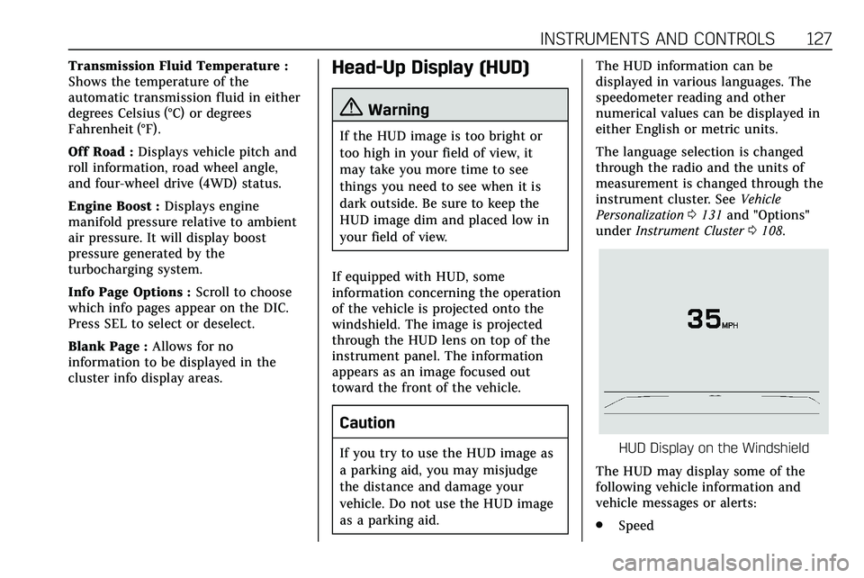
under Instrument Cluster 0108.HUD Display on the Windshield
The HUD may display some of the
following vehicle information and
vehicle messages or alerts:
. Speed
Page 130 of 384
INSTRUMENTS AND CONTROLS 129
Metric
English
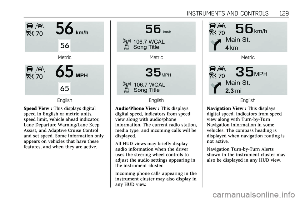
Speed View : This displays digital
speed in English or metric units,
speed limit, vehicle ahead indicator,
Lane Departure Warning/Lane Keep
Assist, and Adaptive Cruise Control
and set speed. Some information only
appears on vehicles that have these
features, and when they are active.
Metric
English
Audio/Phone View : This displays
digital speed, indicators from speed
view along with audio/phone
information. The current radio station,
media type, and incoming calls will be
displayed.
All HUD views may briefly display
audio information when the driver
uses the steering wheel controls to
adjust the audio settings appearing in
the instrument cluster.
Incoming phone calls appearing in the
instrument cluster may also display in
any HUD view.
Metric
English
Navigation View : This displays
digital speed, indicators from speed
view along with Turn-by-Turn
Navigation information in some
vehicles. The compass heading is
displayed when navigation routing is
not active.
Navigation Turn-by-Turn Alerts
shown in the instrument cluster may
also be displayed in any HUD view.
Page 138 of 384
INSTRUMENTS AND CONTROLS 137
Universal Remote
System
SeeRadio Frequency Statement 0358.
Universal Remote System
Programming
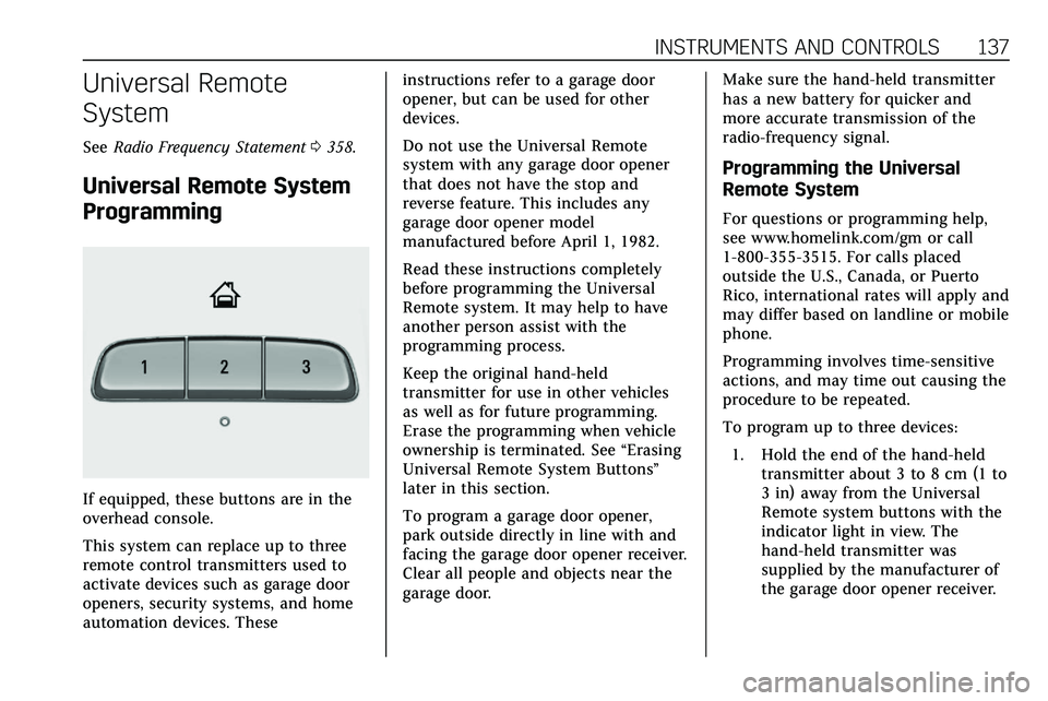
If equipped, these buttons are in the
overhead console.
This system can replace up to three
remote control transmitters used to
activate devices such as garage door
openers, security systems, and home
automation devices. These instructions refer to a garage door
opener, but can be used for other
devices.
Do not use the Universal Remote
system with any garage door opener
that does not have the stop and
reverse feature. This includes any
garage door opener model
manufactured before April 1, 1982.
Read these instructions completely
before programming the Universal
Remote system. It may help to have
another person assist with the
programming process.
Keep the original hand-held
transmitter for use in other vehicles
as well as for future programming.
Erase the programming when vehicle
ownership is terminated. See
“Erasing
Universal Remote System Buttons”
later in this section.
To program a garage door opener,
park outside directly in line with and
facing the garage door opener receiver.
Clear all people and objects near the
garage door. Make sure the hand-held transmitter
has a new battery for quicker and
more accurate transmission of the
radio-frequency signal.
Programming the Universal
Remote System
For questions or programming help,
see www.homelink.com/gm or call
1-800-355-3515. For calls placed
outside the U.S., Canada, or Puerto
Rico, international rates will apply and
may differ based on landline or mobile
phone.
Programming involves time-sensitive
actions, and may time out causing the
procedure to be repeated.
To program up to three devices:
1. Hold the end of the hand-held transmitter about 3 to 8 cm (1 to
3 in) away from the Universal
Remote system buttons with the
indicator light in view. The
hand-held transmitter was
supplied by the manufacturer of
the garage door opener receiver.
Page 139 of 384
138 INSTRUMENTS AND CONTROLS
2. At the same time, press and holdboth the hand-held transmitter
button and one of the three
Universal Remote system
buttons to be used to operate the
garage door. Do not release either
button until the indicator light
changes from a slow to a rapid
flash. Then release both buttons.
Some garage door openers may
require substitution of Step 2
with the procedure under “Radio
Signals for Some Gate Operators”
later in this section.
3. Press and hold the newly programmed Universal Remote
system button for five seconds
while watching the indicator
light and garage door activation.
.If the indicator light stays on
continuously or the garage
door moves when the button
is pressed, then programming
is complete. There is no need
to complete Steps 4–6.
. If the indicator light does not
come on or the garage door
does not move, a second
button press may be required. For a second time,
press and hold the newly
programmed button for
five seconds. If the light stays
on or the garage door moves,
programming is complete.
. If the indicator light blinks
rapidly for two seconds, then
changes to a solid light and
the garage door does not
move, continue with
programming Steps 4–6.
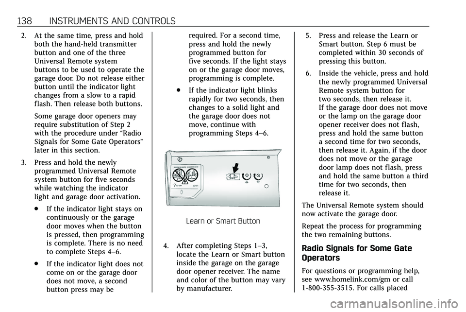
Learn or Smart Button
4. After completing Steps 1–3, locate the Learn or Smart button
inside the garage on the garage
door opener receiver. The name
and color of the button may vary
by manufacturer. 5. Press and release the Learn or
Smart button. Step 6 must be
completed within 30 seconds of
pressing this button.
6. Inside the vehicle, press and hold the newly programmed Universal
Remote system button for
two seconds, then release it.
If the garage door does not move
or the lamp on the garage door
opener receiver does not flash,
press and hold the same button
a second time for two seconds,
then release it. Again, if the door
does not move or the garage
door lamp does not flash, press
and hold the same button a third
time for two seconds, then
release it.
The Universal Remote system should
now activate the garage door.
Repeat the process for programming
the two remaining buttons.
Radio Signals for Some Gate
Operators
For questions or programming help,
see www.homelink.com/gm or call
1-800-355-3515. For calls placed
Page 140 of 384

INSTRUMENTS AND CONTROLS 139
outside the U.S., Canada, or Puerto
Rico, international rates will apply and
may differ based on landline or mobile
phone.
Some radio-frequency laws and gate
operators require transmitter signals
to time out or quit after several
seconds of transmission. This may not
be long enough for the Universal
Remote system to pick up the signal
during programming.
If the programming did not work,
replace Step 2 under“Programming
the Universal Remote System ”with
the following:
Press and hold the Universal Remote
system button while pressing and
releasing the hand-held transmitter
button every two seconds until the
signal has been successfully accepted
by the Universal Remote system. The
Universal Remote system indicator
light will flash slowly at first and then
rapidly. Proceed with Step 3 under
“Programming the Universal Remote
System ”to complete.Universal Remote System
Operation
Using the Universal Remote
System
Press and hold the appropriate
Universal Remote system button for at
least one-half second. The indicator
light will come on while the signal is
being transmitted.
Erasing Universal Remote
System Buttons
Erase all programmed buttons when
vehicle ownership is terminated.
To erase:
1. Press and hold the two outside buttons until the indicator light
begins to flash. This should take
about 10 seconds.
2. Release both buttons.
Reprogramming a Single
Universal Remote System
Button
To reprogram any of the system
buttons: 1. Press and hold any one of the
buttons. Do not release the
button.
2. The indicator light will begin to flash after 20 seconds. Without
releasing the button, proceed
with Step 1 under “Programming
the Universal Remote System.”
Page 148 of 384
INFOTAINMENT SYSTEM 147
Infotainment System
Introduction
Infotainment . . . . . . . . . . . . . . . . . . . . . 147
Introduction
Infotainment
See the infotainment manual for
information on the radio, audio
players, phone, navigation system, and
voice or speech recognition. It also
includes information on settings.
Active Noise Cancellation (ANC)
If equipped, ANC reduces engine noise
in the vehicle’s interior. ANC requires
the factory-installed audio system,
radio, speakers, amplifier (if
equipped), induction system, and
exhaust system to work properly.
Deactivation is required by your dealer
if related aftermarket equipment is
installed.