relay CHERY TIGGO 2009 Service Repair Manual
[x] Cancel search | Manufacturer: CHERY, Model Year: 2009, Model line: TIGGO, Model: CHERY TIGGO 2009Pages: 1903, PDF Size: 33.38 MB
Page 1863 of 1903

Downloaded from www.Manualslib.com manuals search engine VEHICLE FUSE BOX INFORMATION
GENERAL INFORMATION16-38
Description 16-38
Operation 16-38
Power Fuse Box 16-38
Description 16-38
Operation 16-38
Overview 16-39 Front Fuse and Relay Box
16-40
Description 16-40
Operation 16-40
Overview 16-41
Body Fuse and Relay Box 16-42
Description 16-42
Operation 16-42
Overview 16-43
16
16–37Chery Automobile Co., Ltd.
Page 1864 of 1903

Downloaded from www.Manualslib.com manuals search engine GENERAL INFORMATION
Description
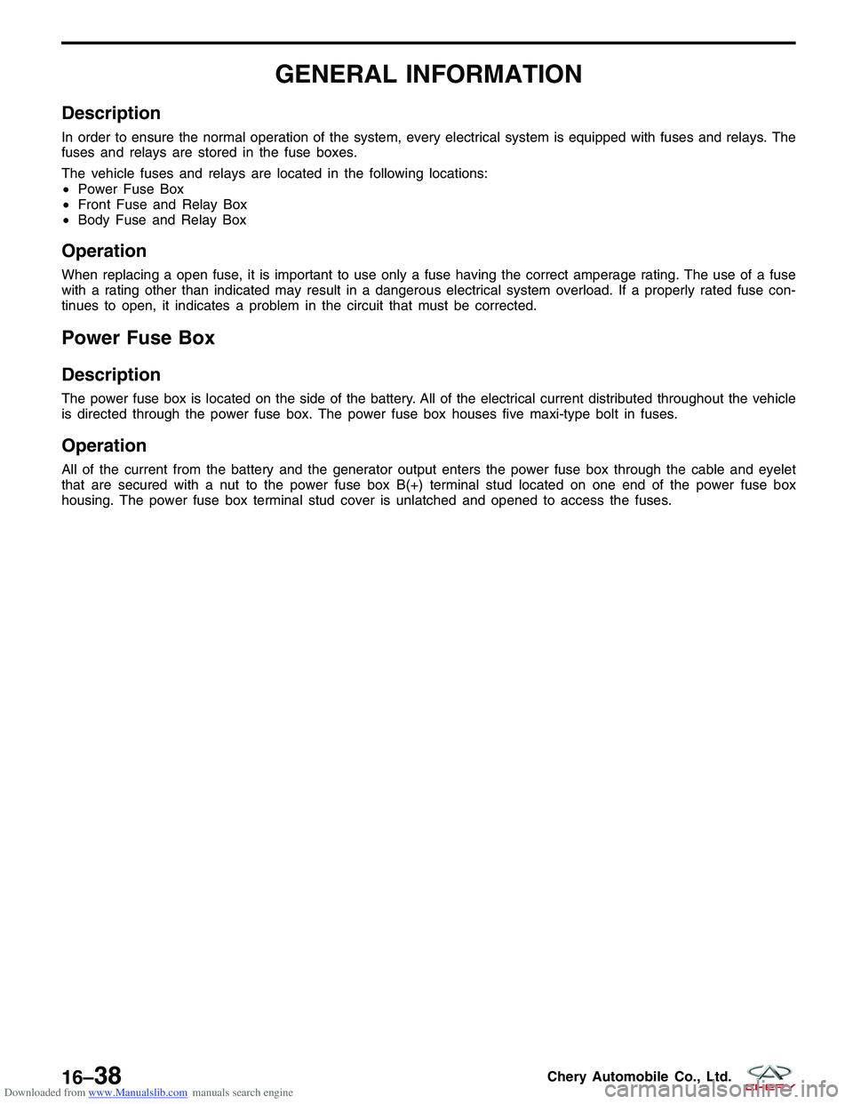
In order to ensure the normal operation of the system, every electrical system is equipped with fuses and relays. The
fuses and relays are stored in the fuse boxes.
The vehicle fuses and relays are located in the following locations:
•Power Fuse Box
• Front Fuse and Relay Box
• Body Fuse and Relay Box
Operation
When replacing a open fuse, it is important to use only a fuse having the correct amperage rating. The use of a fuse
with a rating other than indicated may result in a dangerous electrical system overload. If a properly rated fuse con-
tinues to open, it indicates a problem in the circuit that must be corrected.
Power Fuse Box
Description
The power fuse box is located on the side of the battery. All of the electrical current distributed throughout the vehicle
is directed through the power fuse box. The power fuse box houses five maxi-type bolt in fuses.
Operation
All of the current from the battery and the generator output enters the power fuse box through the cable and eyelet
that are secured with a nut to the power fuse box B(+) terminal stud located on one end of the power fuse box
housing. The power fuse box terminal stud cover is unlatched and opened to access the fuses.
16–38Chery Automobile Co., Ltd.
Page 1866 of 1903

Downloaded from www.Manualslib.com manuals search engine Front Fuse and Relay Box
Description
The front fuse and relay box houses many of the fuses and relays for the vehicles electrical system. The front fuse
and relay box is located on the right side of the engine compartment and under the cowl top of windshield. If the
fuses and relays cannot be serviced, it must be replaced as a unit.
Operation
When a circuit fails, the fuse will blow and remove current from the circuit. The front fuse and relay box is equipped
with a label that identifies each component. The label is printed on the inside of the cover. The power fuse box
identifies the rating of each fuse individually. Turn off the ignition switch, and then replace the fuse.
GENERAL INFORMATION
16–40Chery Automobile Co., Ltd.
Page 1867 of 1903

Downloaded from www.Manualslib.com manuals search engine Overview
Front Fuse And Relay Box
GENERAL INFORMATION
LTSMW170005T
16
16–41Chery Automobile Co., Ltd.
Page 1868 of 1903

Downloaded from www.Manualslib.com manuals search engine Body Fuse and Relay Box
Description
The body fuse and relay box houses many of the fuses and relays for the vehicle’s electrical system. The body fuse
and relay box is situated on the left front side of the interior of the cabin and under the instrument panel, which is
mounted on the cross beam of the instrument panel. All the fuses and relays cannot be serviced it must be replaced
as a unit.
Operation
When a circuit fails, the fuse will blow and remove current from the circuit.
Turn off the ignition switch, and then replace the fuse.
GENERAL INFORMATION
16–42Chery Automobile Co., Ltd.
Page 1869 of 1903

Downloaded from www.Manualslib.com manuals search engine Overview
Body Fuse And Relay Box
GENERAL INFORMATION
LTSMW170006T
16
16–43Chery Automobile Co., Ltd.
Page 1876 of 1903

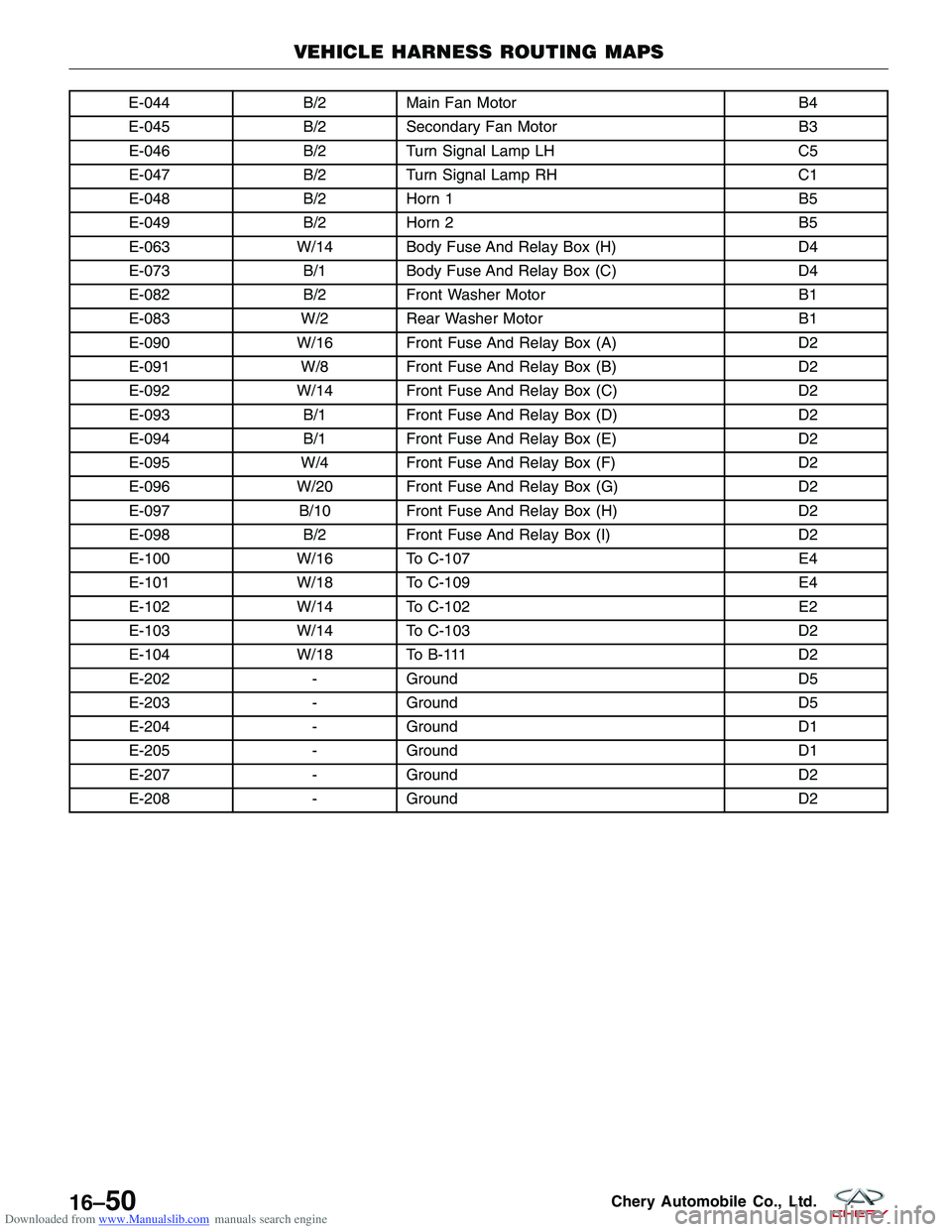
Downloaded from www.Manualslib.com manuals search engine E-044B/2Main Fan Motor B4
E-045 B/2Secondary Fan Motor B3
E-046 B/2Turn Signal Lamp LH C5
E-047 B/2Turn Signal Lamp RH C1
E-048 B/2Horn 1 B5
E-049 B/2Horn 2 B5
E-063 W/14 Body Fuse And Relay Box (H) D4
E-073 B/1Body Fuse And Relay Box (C) D4
E-082 B/2Front Washer Motor B1
E-083 W/2 Rear Washer Motor B1
E-090 W/16 Front Fuse And Relay Box (A) D2
E-091 W/8 Front Fuse And Relay Box (B) D2
E-092 W/14 Front Fuse And Relay Box (C) D2
E-093 B/1Front Fuse And Relay Box (D) D2
E-094 B/1Front Fuse And Relay Box (E) D2
E-095 W/4 Front Fuse And Relay Box (F) D2
E-096 W/20 Front Fuse And Relay Box (G) D2
E-097 B/10 Front Fuse And Relay Box (H) D2
E-098 B/2Front Fuse And Relay Box (I) D2
E-100 W/16 To C-107 E4
E-101 W/18 To C-109 E4
E-102 W/14 To C-102 E2
E-103 W/14 To C-103 D2
E-104 W/18 To B-111 D2
E-202 -Ground D5
E-203 -Ground D5
E-204 -Ground D1
E-205 -Ground D1
E-207 -Ground D2
E-208 -Ground D2
VEHICLE HARNESS ROUTING MAPS
16–50Chery Automobile Co., Ltd.
Page 1882 of 1903

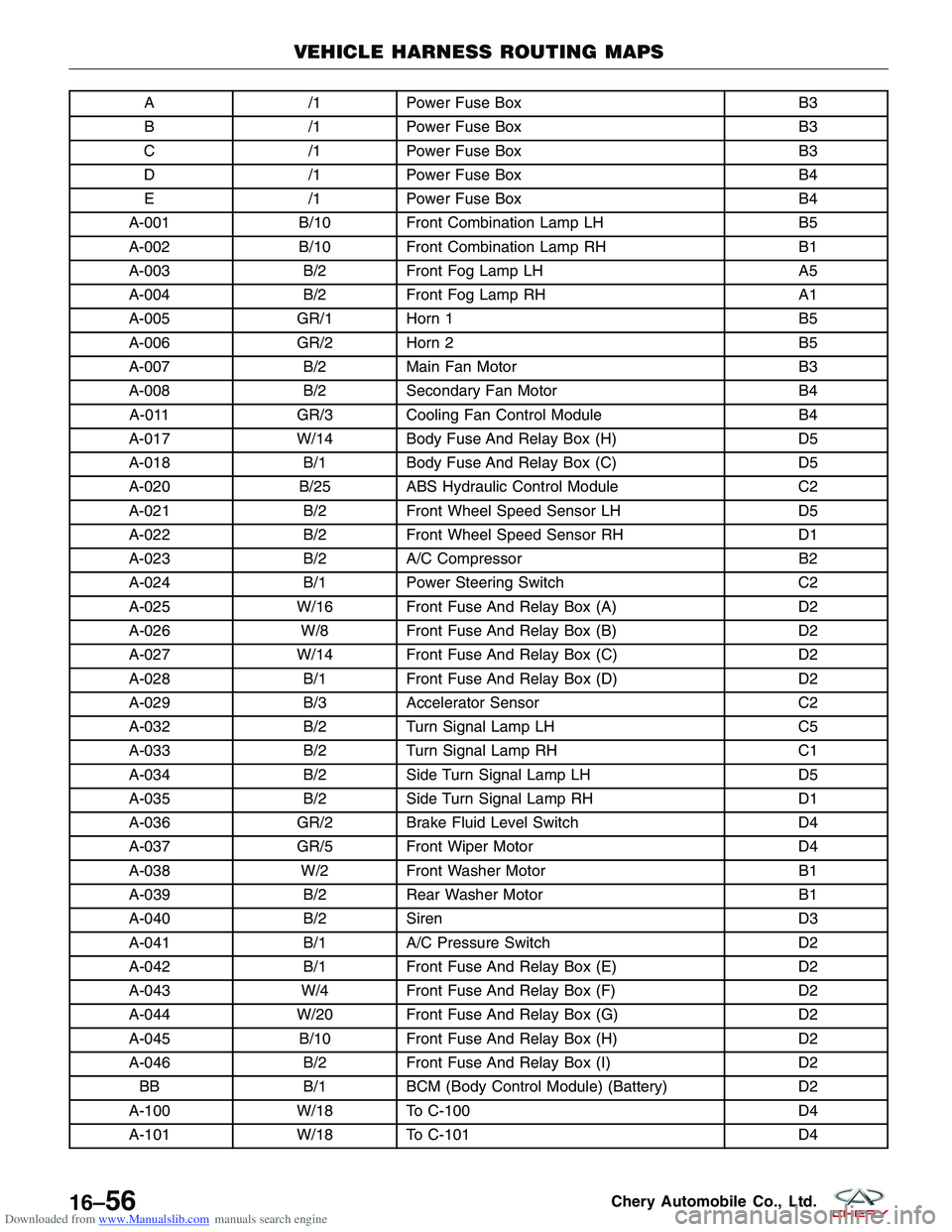
Downloaded from www.Manualslib.com manuals search engine A/1Power Fuse Box B3
B /1Power Fuse Box B3
C /1Power Fuse Box B3
D /1Power Fuse Box B4
E /1Power Fuse Box B4
A-001 B/10 Front Combination Lamp LH B5
A-002 B/10 Front Combination Lamp RH B1
A-003 B/2Front Fog Lamp LH A5
A-004 B/2Front Fog Lamp RH A1
A-005 GR/1 Horn 1 B5
A-006 GR/2 Horn 2 B5
A-007 B/2Main Fan Motor B3
A-008 B/2Secondary Fan Motor B4
A-011 GR/3 Cooling Fan Control Module B4
A-017 W/14 Body Fuse And Relay Box (H) D5
A-018 B/1Body Fuse And Relay Box (C) D5
A-020 B/25 ABS Hydraulic Control Module C2
A-021 B/2Front Wheel Speed Sensor LH D5
A-022 B/2Front Wheel Speed Sensor RH D1
A-023 B/2A/C Compressor B2
A-024 B/1Power Steering Switch C2
A-025 W/16 Front Fuse And Relay Box (A) D2
A-026 W/8 Front Fuse And Relay Box (B) D2
A-027 W/14 Front Fuse And Relay Box (C) D2
A-028 B/1Front Fuse And Relay Box (D) D2
A-029 B/3Accelerator Sensor C2
A-032 B/2Turn Signal Lamp LH C5
A-033 B/2Turn Signal Lamp RH C1
A-034 B/2Side Turn Signal Lamp LH D5
A-035 B/2Side Turn Signal Lamp RH D1
A-036 GR/2 Brake Fluid Level Switch D4
A-037 GR/5 Front Wiper Motor D4
A-038 W/2 Front Washer Motor B1
A-039 B/2Rear Washer Motor B1
A-040 B/2Siren D3
A-041 B/1A/C Pressure Switch D2
A-042 B/1Front Fuse And Relay Box (E) D2
A-043 W/4 Front Fuse And Relay Box (F) D2
A-044 W/20 Front Fuse And Relay Box (G) D2
A-045 B/10 Front Fuse And Relay Box (H) D2
A-046 B/2Front Fuse And Relay Box (I) D2
BB B/1BCM (Body Control Module) (Battery) D2
A-100 W/18 To C-100 D4
A-101 W/18 To C-101 D4
VEHICLE HARNESS ROUTING MAPS
16–56Chery Automobile Co., Ltd.
Page 1885 of 1903

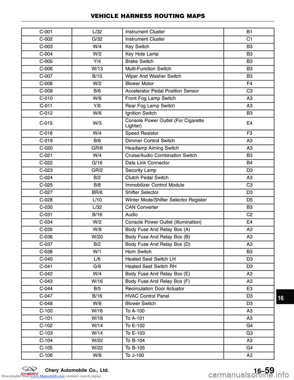
Downloaded from www.Manualslib.com manuals search engine C-001L/32 Instrument Cluster B1
C-002 G/32 Instrument Cluster C1
C-003 W/4 Key Switch B3
C-004 W/2 Key Hole Lamp B3
C-005 Y/4Brake Switch B3
C-006 W/13 Multi-Function Switch B3
C-007 B/10 Wiper And Washer Switch B3
C-008 W/2 Blower Motor F4
C-009 B/6Accelerator Pedal Position Sensor C3
C-010 W/6 Front Fog Lamp Switch A3
C-011 Y/6Rear Fog Lamp Switch A3
C-012 W/6 Ignition Switch B3
C-015 W/3Console Power Outlet (For Cigarette
Lighter) E4
C-016 W/4 Speed Resistor F3
C-019 B/6Dimmer Control Switch A3
C-020 GR/6 Headlamp Aiming Switch A3
C-021 W/4 Cruise/Audio Combination Switch B3
C-022 G/16 Data Link Connector B4
C-023 GR/2 Security Lamp D3
C-024 B/2Clutch Pedal Switch A3
C-025 B/8Immobilizer Control Module C3
C-027 BR/6 Shifter Selector D3
C-028 L/10 Winter Mode/Shifter Selector Register D5
C-030 L/32 CAN Converter B3
C-031 B/16 Audio C2
C-034 W/2 Console Power Outlet (Illumination) E4
C-035 W/8 Body Fuse And Relay Box (A) A3
C-036 W/20 Body Fuse And Relay Box (B) A3
C-037 B/2Body Fuse And Relay Box (D) A3
C-038 W/1 Horn Switch B3
C-040 L/6Heated Seat Switch LH D3
C-041 G/6Heated Seat Switch RH D3
C-042 W/4 Body Fuse And Relay Box (E) A3
C-043 W/16 Body Fuse And Relay Box (F) A3
C-044 B/5Recirculation Door Actuator E3
C-047 B/16 HVAC Control Panel D3
C-048 W/8 Blower Switch D3
C-100 W/16 To A-100 A3
C-101 W/18 To A-101 A3
C-102 W/14 To E-102 G4
C-103 W/14 To E-103 G3
C-104 W/22 To B-104 A3
C-105 W/22 To B-105 G4
C-106 W/6 To J-100 A3
VEHICLE HARNESS ROUTING MAPS
16
16–59Chery Automobile Co., Ltd.
Page 1888 of 1903

Downloaded from www.Manualslib.com manuals search engine B-003GR/15 BCM (Body Control Module) D1
B-004 B/12 BCM (Body Control Module) D1
B-005 B/8BCM (Body Control Module) D1
B-006 B/10 Body Fuse And Relay Box (G) C2
B-008 W/1 Parking Brake Switch D2
B-011 B/4Downstream Oxygen Sensor (With
MITSUBISHI 2.4L Engine System) D2
B-012 W/2 Rear Power Outlet LH D5
B-017 L/6Driver Seat Assembly C2
B-018 L/6Heated Seat RH D2
B-019 W/6 Rear Combination Lamp LH D5
B-020 W/6 Rear Combination Lamp RH D4
B-021 W/2 Rear Wheel Speed Sensor LH D4
B-022 W/2 Rear Wheel Speed Sensor RH D3
B-023 B/3Decelerator Sensor D2
B-032a B/4Fuel Level Sensor And Fuel Pump (With
ACTECO Engine System) D3
B-032b B/4Fuel Level Sensor And Fuel Pump (With
MITSUBISHI 2.4L Engine System) D3
B-100 W/18 To D-100 C2
B-101 W/14 To D-101 C2
B-102 W/14 To G-100 D1
B-103 W/10 To G-101 D1
B-104 W/22 To C-104 C2
B-105 W/22 To C-105 D1
B-106 W/18 To A-103 E1
B-107 W/14 To I-100 C4
B-108 W/14 To H-100 D2
B-110 W/14 To L-100 D4
B-111 W/18 To E-104 E1
B-201 -Ground D1
B-202 -Ground D4
B-203 -Ground D2
B-204 -Ground D5
B-205 -Ground (With MITSUBISHI 2.4L Engine
System) D5
B-206 -Ground (With ACTECO Engine System) D4
VEHICLE HARNESS ROUTING MAPS
16–62Chery Automobile Co., Ltd.