oil level CHERY TIGGO 2009 Service User Guide
[x] Cancel search | Manufacturer: CHERY, Model Year: 2009, Model line: TIGGO, Model: CHERY TIGGO 2009Pages: 1903, PDF Size: 33.38 MB
Page 194 of 1903
Downloaded from www.Manualslib.com manuals search engine CONDITIONPOSSIBLE CAUSES CORRECTION
Oil Pressure Drop 1. Low oil level.
2. Faulty oil pressure sending unit.
3. Low oil pressure.
4. Clogged oil filter.
5. Thin or diluted oil.
6. Excessive bearing clearance.1. Check engine oil level.
2. Install new sending unit.
3. Check sending unit and main
bearing oil clearance.
4. Install new oil filter.
5. Change oil to correct viscosity.
6. Measure bearings for correct
clearance.
Oil Leaks 1. Misaligned or deteriorated
gaskets.
2. Loose fastener, broken or porous
metal part.
3. Misaligned or deteriorated cup or
threaded plug.1. Replace gasket.
2. Tighten, repair or replace the part.
3. Replace if necessary.
Oil Consumption Or Spark Plugs
Fouled 1. PCV system malfunction.
2. Worn, scuffed or broken rings.
3. Carbon in oil ring slots.
4. Rings fitted too tightly in grooves.
5. Worn valve guide(s).
6. Valve stem seal(s) worn or
damaged.1. Check system and repair if
necessary.
2. Hone cylinder bores. Install new
rings.
3. Install new rings.
4. Remove rings and check grooves.
If groove is not proper width, replace
piston.
5. Replace cylinder head.
6. Replace seal(s).
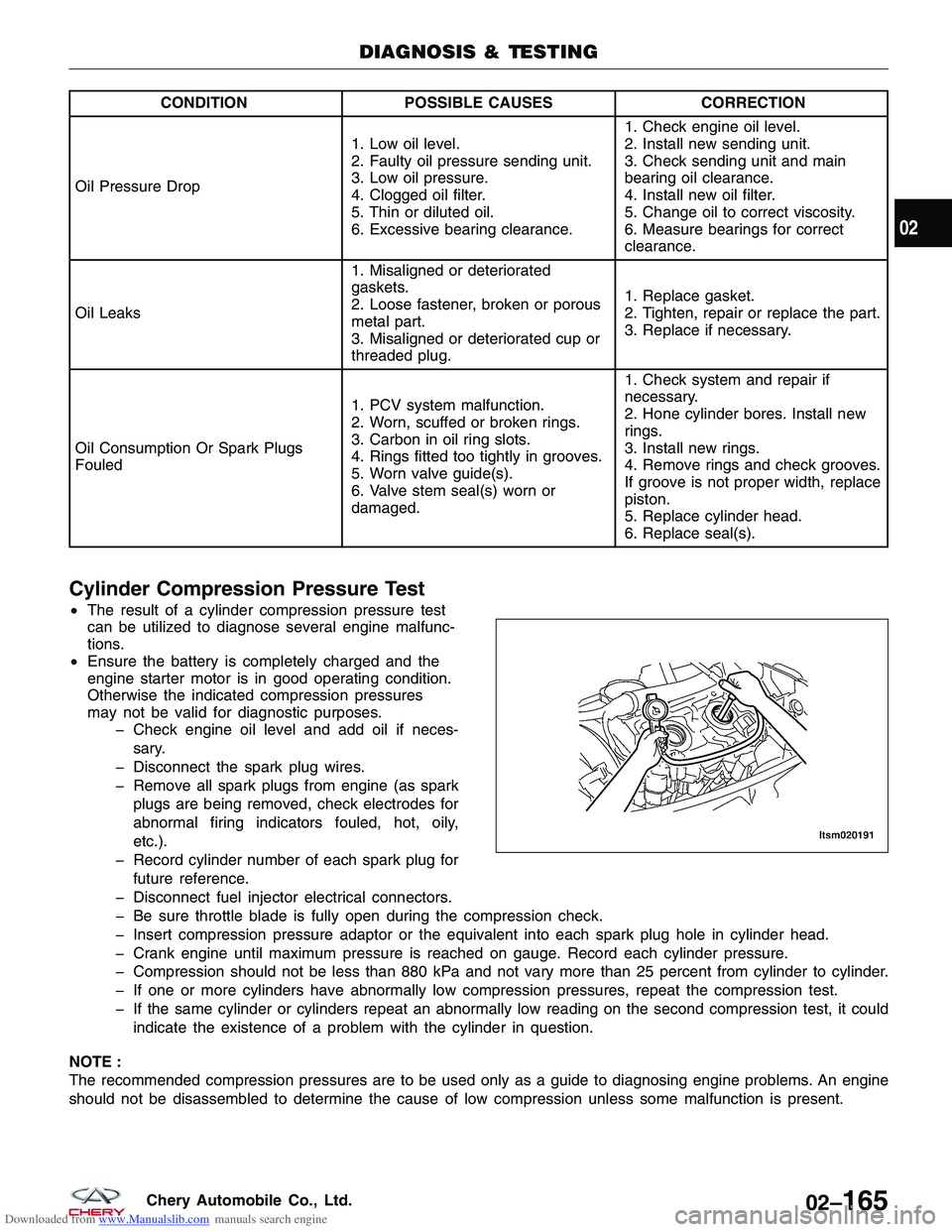
Cylinder Compression Pressure Test
•
The result of a cylinder compression pressure test
can be utilized to diagnose several engine malfunc-
tions.
• Ensure the battery is completely charged and the
engine starter motor is in good operating condition.
Otherwise the indicated compression pressures
may not be valid for diagnostic purposes.
Check engine oil level and add oil if neces-
sary.
Disconnect the spark plug wires.
Remove all spark plugs from engine (as spark plugs are being removed, check electrodes for
abnormal firing indicators fouled, hot, oily,
etc.).
Record cylinder number of each spark plug for future reference.
Disconnect fuel injector electrical connectors.
Be sure throttle blade is fully open during the compression check.
Insert compression pressure adaptor or the equivalent into each spark plug hole in cylinder head.
Crank engine until maximum pressure is reached on gauge. Record each cylinder pressure.
Compression should not be less than 880 kPa and not vary more than 25 percent from cylinder to cylinder.
If one or more cylinders have abnormally low compression pressures, repeat the compression test.
If the same cylinder or cylinders repeat an abnormally low reading on the second compression test, it could indicate the existence of a problem with the cylinder in question.
NOTE :
The recommended compression pressures are to be used only as a guide to diagnosing engine problems. An engine
should not be disassembled to determine the cause of low compression unless some malfunction is present.
DIAGNOSIS & TESTING
LTSM020191
02
02–165Chery Automobile Co., Ltd.
Page 195 of 1903
Downloaded from www.Manualslib.com manuals search engine Cylinder Head Gasket Test
•A cylinder head gasket leak can be located between adjacent cylinders, between a cylinder and the adjacent
water jacket or from an oil passage to the exterior of the engine.
• Possible indications of the cylinder head gasket leaking between adjacent cylinders are:
Loss of engine power
Engine misfiring
Poor fuel economy
• Possible indications of the cylinder head gasket leaking between a cylinder and an adjacent water jacket are:
Engine overheating
Loss of coolant
Excessive steam (white smoke) emitting from exhaust
Coolant foaming
Engine Oil Pressure Test
1. Check the engine oil level.
2. Disconnect the oil pressure switch electrical connector.
3. Remove the oil pressure switch.
4. Install the mechanical oil pressure gauge.
5. Start the engine and warm to normal operating temperature.
6. After the engine has been warmed up, check that the oil pressure is within the specifications. Standard Oil Pressure: At 750 ± 50 RPM: 0.8 MPa
7. Stop the engine.
8. Remove the oil pressure gauge.
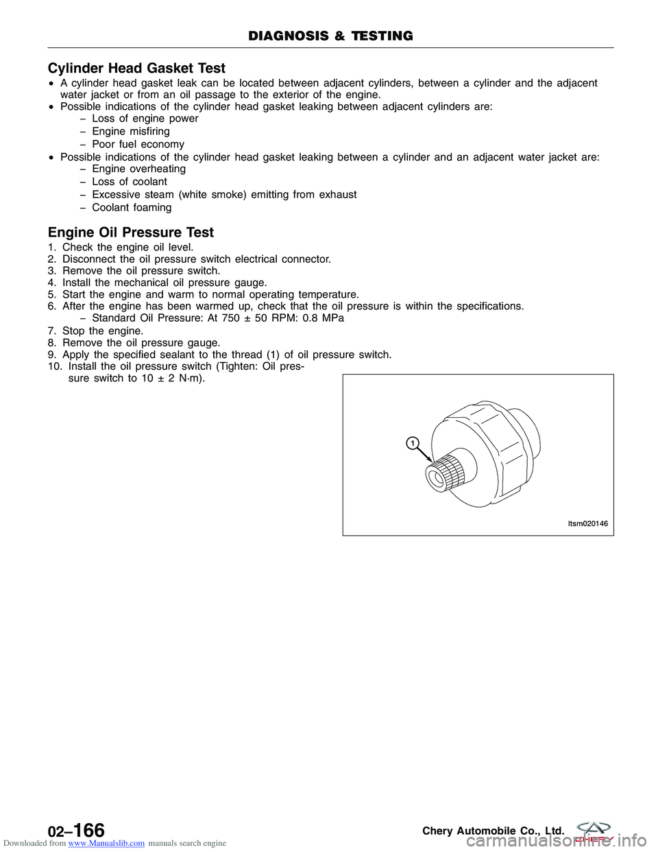
9. Apply the specified sealant to the thread (1) of oil pressure switch.
10. Install the oil pressure switch (Tighten: Oil pres- sure switch to 10 ± 2 N·m).
DIAGNOSIS & TESTING
LTSM020146
02–166Chery Automobile Co., Ltd.
Page 242 of 1903
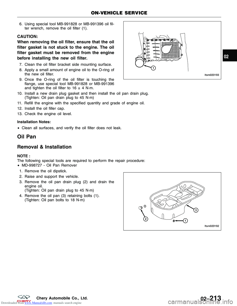
Downloaded from www.Manualslib.com manuals search engine 6. Using special tool MB-991828 or MB-991396 oil fil-ter wrench, remove the oil filter (1).
CAUTION:
When removing the oil filter, ensure that the oil
filter gasket is not stuck to the engine. The oil
filter gasket must be removed from the engine
before installing the new oil filter.
7. Clean the oil filter bracket side mounting surface.
8. Apply a small amount of engine oil to the O-ring ofthe new oil filter.
9. Once the O-ring of the oil filter is touching the flange, use special tool MB-991828 or MB-991396
and tighten the oil filter to 16 ± 4 N·m.
10. Install a new drain plug gasket and then install the oil pan drain plug. (Tighten: Oil pan drain plug to 45 N·m)
11. Refill the engine with the specified quantity and grade of engine oil.
12. Install the oil filler cap.
13. Check the engine oil level.
Installation Notes:
• Clean all surfaces, and verify the oil filter does not leak.
Oil Pan
Removal & Installation
NOTE :
The following special tools are required to perform the repair procedure:
•MD-998727 - Oil Pan Remover
1. Remove the oil dipstick.
2. Raise and support the vehicle.
3. Remove the oil pan drain plug (2) and drain the engine oil.
(Tighten: Oil pan drain plug to 45 N·m)
4. Remove the oil pan (3) retaining bolts (1). (Tighten: Oil pan bolts to 18 N·m)
ON-VEHICLE SERVICE
LTSM020193
LTSM020192
02
02–213Chery Automobile Co., Ltd.
Page 249 of 1903
Downloaded from www.Manualslib.com manuals search engine Inspection
NOTE :
All measurements should be taken with the engine block at room temperature, 21°C.
Engine Block
•Clean cylinder block thoroughly and check all core hole plugs for evidence of leaking.
• Examine block and cylinder bores for cracks or fractures.
• Check block deck surfaces for flatness. Deck surface must be within service limit of 0.050 mm.
Cylinder Bore
• The cylinder walls should be checked for out-of-round and taper with cylinder indicator or equivalent. If the cyl-
inder walls are badly scuffed or scored, the cylinder block should be replaced, and new pistons and rings fitted.
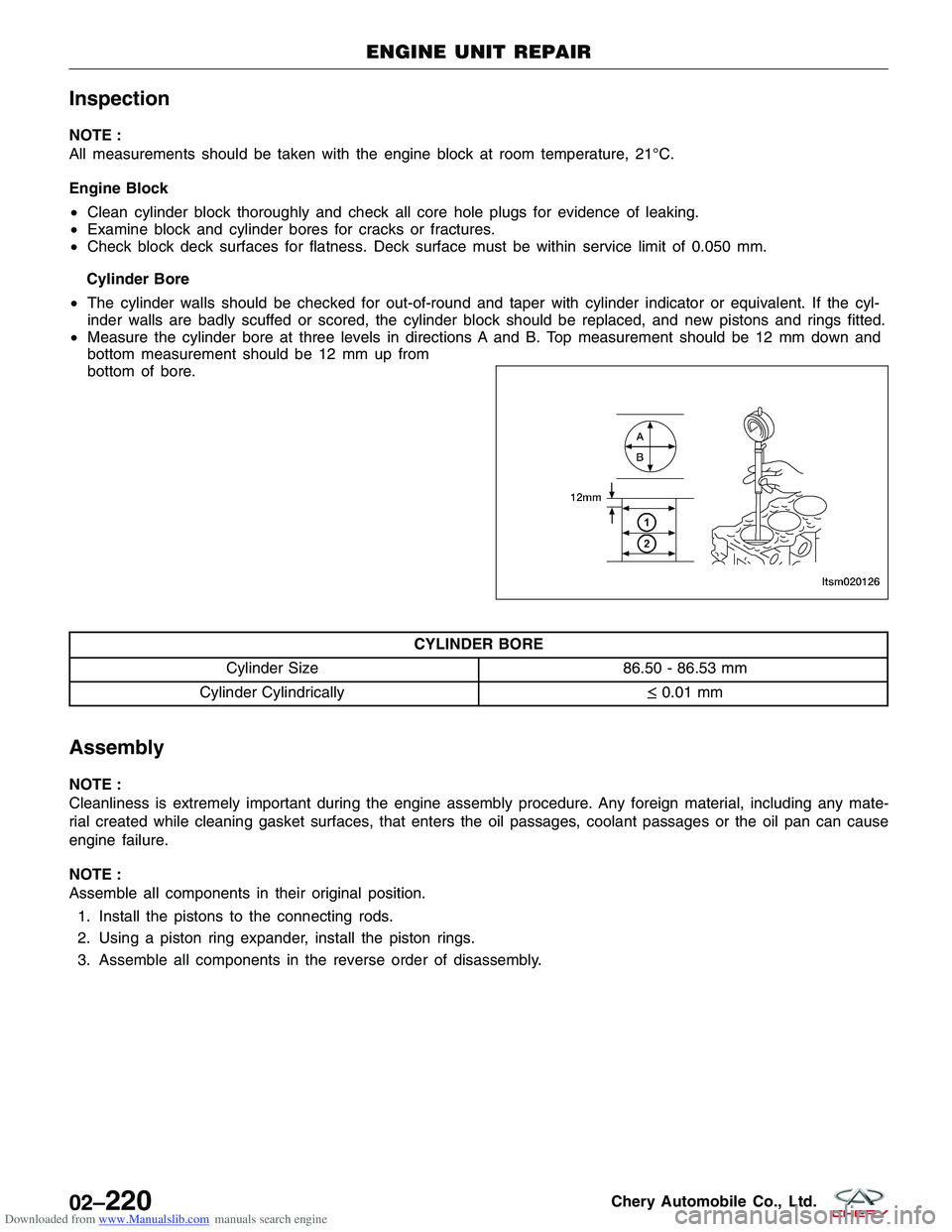
• Measure the cylinder bore at three levels in directions A and B. Top measurement should be 12 mm down and
bottom measurement should be 12 mm up from
bottom of bore.
CYLINDER BORE
Cylinder Size 86.50 - 86.53 mm
Cylinder Cylindrically ≤0.01 mm
Assembly
NOTE :
Cleanliness is extremely important during the engine assembly procedure. Any foreign material, including any mate-
rial created while cleaning gasket surfaces, that enters the oil passages, coolant passages or the oil pan can cause
engine failure.
NOTE :
Assemble all components in their original position.
1. Install the pistons to the connecting rods.
2. Using a piston ring expander, install the piston rings.
3. Assemble all components in the reverse order of disassembly.
ENGINE UNIT REPAIR
LTSM020126
02–220Chery Automobile Co., Ltd.
Page 919 of 1903
Downloaded from www.Manualslib.com manuals search engine •Hoses and clamps
• Coolant temperature sensor
• Coolant temperature sensor (for instrument cluster) (with 2.4L engine)
• Heater core
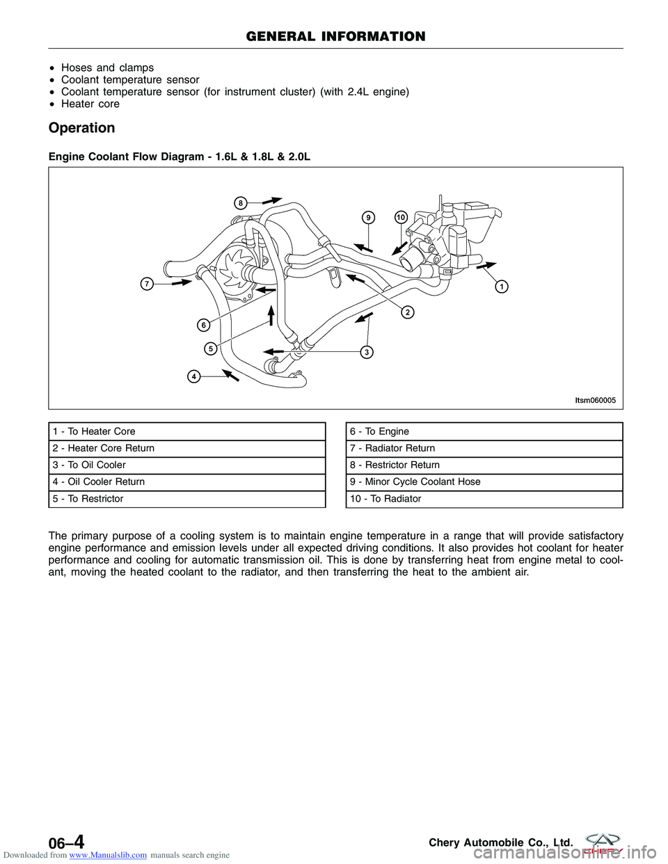
Operation
The primary purpose of a cooling system is to maintain engine temperature in a range that will provide satisfactory
engine performance and emission levels under all expected driving conditions. It also provides hot coolant for heater
performance and cooling for automatic transmission oil. This is done by transferring heat from engine metal to cool-
ant, moving the heated coolant to the radiator, and then transferring the heat to the ambient air. Engine Coolant Flow Diagram - 1.6L & 1.8L & 2.0L
1 - To Heater Core
2 - Heater Core Return
3 - To Oil Cooler
4 - Oil Cooler Return
5 - To Restrictor6 - To Engine
7 - Radiator Return
8 - Restrictor Return
9 - Minor Cycle Coolant Hose
10 - To Radiator
GENERAL INFORMATION
LTSM060005
06–4Chery Automobile Co., Ltd.
Page 926 of 1903
Downloaded from www.Manualslib.com manuals search engine DIAGNOSIS AND TESTING
Cooling System Pressure Test
WARNING!
Always allow the engine to cool before opening the cooling system. Do not remove the coolant pressure relief
cap when the engine is operating or the cooling system is hot. The cooling system is under pressure; steam and
hot liquid can come out forcefully when the cap is loosened slightly. Failure to follow these instructions may
result in serious personal injury.
CAUTION:
Do not pressurize the cooling system beyond the maximum pressure listed in the specifications
table in this section, or cooling system components can be damaged.
1. Turn the engine off.
2. Check the engine coolant level. Adjust the coolant level as necessary.
3. Attach the pressure tester to the coolant recovery reservoir. Install a pressure test pump to the quick-connectfitting of the test adapter.
4. Pressurize the engine cooling system to 111 kPa. Observe the gauge reading for approximately 2 minutes. Pres- sure should not drop during this time. If the pressure drops within this time, inspect for leaks and repair as nec-
essary.
5. If no leaks are found and the pressure drops, the pressure relief cap may be leaking. Install a new pressure relief cap and retest the system.
6. If no leaks are found after a new pressure relief cap is installed, and the pressure drops, the leak may be inter- nal to the radiator transmission cooler (if equipped). Inspect the coolant for transmission fluid and the transmis-
sion fluid for coolant. Repair as necessary.
7. If there is no contamination of the coolant or transmission fluid, the leak may be internal to the engine. Inspect the coolant for engine oil and the engine oil for coolant.
8. Release the system pressure by loosening the pressure relief cap. Check the coolant level and adjust as nec- essary.
Cooling System Concentration Test
CAUTION:
Do not mix types of coolant, corrosion protection will be severely reduced.
Coolant concentration should be checked when any additional coolant is added to the cooling system or after a cool-
ant drain, flush and refill. The coolant mixture offers optimum engine cooling and protection against corrosion when
mixed to a freeze point of -37°C to -46°C. The use of a hydrometer or a refractometer can be used to test coolant
concentration.
06
06–11Chery Automobile Co., Ltd.
Page 1340 of 1903
Downloaded from www.Manualslib.com manuals search engine GENERAL INFORMATION
Description
Vehicle wheel alignment is the positioning of all interrelated front and rear suspension angles. These angles affect the
handling and steering of the vehicle when it is in motion. Proper wheel alignment is essential for efficient steering,
good directional stability, and proper tire wear.
The method of checking a vehicle’s front and rear wheel alignment varies depending on the manufacturer and type
of equipment used. The manufacturer’s instructions should always be followed to ensure accuracy of the alignment.
On this vehicle, the suspension angles that can be adjusted are as follows:
Front Axle
•Camber
• Caster
• Toe-in
Rear Axle
• Camber
• Toe-in
Check the wheel alignment and make all wheel alignment adjustments with the vehicle standing at its proper curb
height specification. Curb height is the normal riding height of the vehicle. It is measured from a certain point on the
vehicle to the ground or a designated area while the vehicle is sitting on a flat, level surface.
Operation
Curb Height Measurement
The wheel alignment is to be checked and all alignment adjustments made with the vehicle at its required curb height
specification.
• Vehicle height is to be checked with the vehicle on a flat, level surface, preferably a vehicle alignment rack.
• The tires are to be inflated to the recommended pressure.
• All tires are to be the same size as standard equipment.
• Vehicle height is checked with the fuel tank full of fuel, and no passenger or luggage compartment load.
• Vehicle height is not adjustable.
• If the measurement is not within specifications, inspect the vehicle for bent or weak suspension components.
• Compare the parts tag on the suspect coil spring(s) to the parts book and the vehicle sales code, checking for
a match.
• Once removed from the vehicle, compare the coil spring height to a new or known good coil spring. The
heights should vary if the suspect spring is weak.
NOTE :
Prior to reading the curb height measurement, the front and rear of the vehicle must be jounced to settle the sus-
pension. Induce jounce by pushing down on the center of the bumper (fascia), using care not to damage the vehicle,
moving the vehicle up and down, gradually increasing the suspension travel with each stroke. Release the bumper at
the bottom of each stroke, repeating this action several times. Perform this to both front and rear suspensions an
equal number of times.
Pre-Wheel Alignment Inspection
Before any attempt is made to change or correct the wheel alignment, the following inspection and necessary cor-
rections must be made to the vehicle to ensure proper alignment. 1. Verify the fuel tank is full of fuel. If the fuel tank is not full, the reduction in weight will affect the curb height of the vehicle and the alignment specifications.
2. The passenger and luggage compartments of the vehicle should be free of any load that is not factory equip- ment.
10
10–39Chery Automobile Co., Ltd.
Page 1495 of 1903
Downloaded from www.Manualslib.com manuals search engine CONDITIONPOSSIBLE CAUSES CORRECTION
Normal Pressures, But A/C
Performance Test Air Temperatures
At Center Panel Outlet Are Too High · Excessive refrigerant oil in system.
· Blend door inoperative or sealing
improperly.
· Blend door actuator faulty or
inoperative.· Recover the refrigerant from the
refrigerant system and inspect the
refrigerant oil content. Restore the
refrigerant oil to the proper level, if
required.
· Inspect the blend door for proper
operation and sealing. Repair if
required.
· Replace if faulty.
The Low Side Pressure Is Normal
Or Slightly Low, And The High Side
Pressure Is Too Low · Low refrigerant system charge.
· Refrigerant flow through the
accumulator is restricted.
· Refrigerant flow through the
evaporator is restricted.
· Faulty compressor.· Test the refrigerant system for
leaks. Repair, evacuate and charge
the refrigerant system, if required.
· Replace the restricted accumulator,
if required.
· Replace the restricted evaporator
coil, if required.
· Replace the compressor, if
required.
The Low Side Pressure Is Normal
Or Slightly High, And The High Side
Pressure Is Too High · Condenser air flow restricted.
· Inoperative cooling fan.
· Refrigerant system overcharged.
· Air in the refrigerant system.
· Engine overheating.· Check the condenser for damaged
fins, foreign objects obstructing air
flow through the condenser fins, and
missing or improperly installed air
seals. Clean, repair, or replace
components as required.
· Test the cooling fan and replace, if
required.
· Recover the refrigerant from the
refrigerant system. Charge the
refrigerant system to the proper
level, if required.
· Test the refrigerant system for
leaks. Repair, evacuate and charge
the refrigerant system, if required.
· Test the cooling system and repair
as necessary.
The Low Side Pressure Is Too High,
And The High Side Pressure Is Too
Low · Accessory drive belt slipping.
· Faulty compressor.· Inspect the accessory drive belt
condition and tension. Tighten or
replace the accessory drive belt, if
required.
· Replace the compressor, if
required.
The Low Side Pressure Is Too Low,
And The High Side Pressure Is Too
High · Restricted refrigerant flow through
the refrigerant lines.
· Restricted refrigerant flow through
the A/C accumulator.
· Restricted refrigerant flow through
the condenser.
· Faulty A/C expansion valve.· Inspect the refrigerant lines for
kinks, tight bends or improper
routing. Correct the routing or
replace the refrigerant line, if
required.
· Replace the accumulator if
restricted.
· Replace the restricted condenser, if
required.
· Test A/C expansion valve and
replace, if required.
DIAGNOSIS & TESTING
13
13–13Chery Automobile Co., Ltd.
Page 1518 of 1903
Downloaded from www.Manualslib.com manuals search engine 12. If the noise is from liquid refrigerant slugging in the A/C suction line, replace the A/C accumulator and check therefrigerant oil level and the refrigerant system charge.
13. If a slugging condition still exists after replacing the A/C accumulator, replace the A/C compressor.
Refrigerant System Leaks
WARNING!
R-134a service equipment or vehicle A/C systems should not be pressure tested or leak tested with compressed
air. Mixture of air and R-134a can be combustible at elevated pressures. These mixtures are potentially danger-
ous and may result in fire or explosion causing property damage, personal injury or death. Avoid breathing A/C
refrigerant and lubricant vapor or mist. Exposure may irritate eyes, nose and throat. Use only approved service
equipment meeting SAE requirements to discharge an R-134a system. If accidental system discharge occurs,
ventilate work area before resuming service.
NOTE :
If the A/C refrigerant system charge is empty or low, a leak in the A/C system is likely. Inspect all A/C lines, fittings
and components for an oily residue. Oil residue can be an indicator of an A/C system leak location.
NOTE :
The only way to correctly determine if the refrigerant system is fully charged with R-134a is to completely evacuate
and recharge the A/C system.
Refrigerant System Empty
1. Evacuate the refrigerant system to the lowest degree of vacuum possible. Determine if the system holds a vac- uum for 15 minutes. If vacuum is held, a leak is probably not present. If system will not maintain vacuum level,
proceed to STEP 2.
2. Prepare and dispense 0.3 kilograms of R-134a refrigerant into the evacuated refrigerant system and proceed to STEP 1 of the System Low procedure.
Refrigerant System Low
1. Position the vehicle in a wind-free work area. This will aid in detecting small leaks.
2. Operate the heating-A/C system with the engine at idle under the following conditions for at least 5 minutes:Doors or windows open, transaxle in Park or Neutral with the parking brake set (depending on application), A/C-
Heater controls set to outside air, full cool, panel mode, high blower and with A/C compressor engaged.
3. Shut the vehicle Off and wait2-7minutes. Then use an electronic leak detector that is designed to detect R-134a refrigerant and search for leaks. Fittings, lines or components that appear to be oily usually indicate a
refrigerant leak. To inspect the A/C evaporator for leaks, insert the leak detector probe into the drain tube open-
ing or an air outlet. A dye for R-134a is available to aid in leak detection. Use only approved refrigerant dye.
CAUTION:
A leak detector only designed for R-12 refrigerant will not detect leaks in an R-134a refrigerant sys-
tem.
DIAGNOSIS & TESTING
13–36Chery Automobile Co., Ltd.
Page 1603 of 1903
Downloaded from www.Manualslib.com manuals search engine CHIME
Description
The chime is located in the Instrument Cluster (IC). The chime warning system is an audible notification to the driver.
The chime warning system is designed to alert the driver of a vehicle problem or condition.
Operation
The Instrument Cluster (IC) uses hard wired inputs from various sensors and switches to activate the chime. The
sensors and switches are located throughout the vehicle. The following conditions will cause the chime to operate:
•Turn signal on
• Hazard warning flashers on
• Seat belt unbuckled
• Low fuel level
• Low oil pressure
• Low brake fluid level
• Doors unlocked
CHIME
15
15–19Chery Automobile Co., Ltd.