air filter CHERY TIGGO 2009 Service Owner's Guide
[x] Cancel search | Manufacturer: CHERY, Model Year: 2009, Model line: TIGGO, Model: CHERY TIGGO 2009Pages: 1903, PDF Size: 33.38 MB
Page 862 of 1903

Downloaded from www.Manualslib.com manuals search engine The ECM will only energize the solenoid when the engine is at operating temperature, but will de-energize it during
periods of deceleration. When de-energized, no vapors are purged. The pulse-width modulated canister control valve
modulates the fuel vapor purge rate from the vapor canister and fuel tank to the engine intake manifold. 2.4L
1 - Fuel Tank2 - Canister
3 - Canister Control Valve 4 - EGR Valve5 - Air Filter Assembly 6 - Throttle Valve
GENERAL INFORMATION
LTSM030031
03–578Chery Automobile Co., Ltd.
Page 868 of 1903

Downloaded from www.Manualslib.com manuals search engine ON-VEHICLE SERVICE
Canister Control Valve 1.6L & 1.8L & 2.0L
Description
This vehicle uses a pulse-width modulated canister control valve. The canister control valve regulates the rate of
vapor flow from the vapor canister to the throttle body. The Engine Control Module (ECM) controls the frequency at
which the canister control valve operates in order to accommodate the vapor volume for each cylinder.
Operation
The canister control valve is installed near of the engine air filter. The Engine Control Module (ECM) controls the
opening and closing of the canister control valve. When the ECM relay is energized, the canister control valve
switches from closed to open.
Removal & Installation
1. Disconnect the negative battery cable.
2. Disconnect the canister control valve electrical con-nector.
3. Disconnect the lines from canister control valve (1).
4. Remove canister control valve (1) from the bracket.
5. Installation is in the reverse order of removal.
Canister Control Solenoid Valve 2.4L
Description
The canister control valve is located near of the engine air filter.
Operation
The Engine Control Module (ECM) controls the opening and closing of the canister control valve. When the ECM
relay is energized, the canister control valve switches from closed to open. The ECM uses a pulse-width modulated
canister control valve to regulates the rate of vapor flow from the vapor canister to the throttle body. The ECM con-
BESM030027
BESM030014
03–584Chery Automobile Co., Ltd.
Page 875 of 1903

Downloaded from www.Manualslib.com manuals search engine GENERAL INFORMATION
Description
The fuel system consists of a fuel tank with a reservoir, fuel pump, fuel filter, fuel delivery line, fuel rail, fuel rail pulse
damper and fuel injectors. The Engine Control Module (ECM) controls the fuel system based on signal inputs. The
immobilizer module signals the ECM to activate the fuel system. If the ECM does not receive the proper signal from
the immobilizer module, the ECM will not allow the fuel system to operate.
•The ACTECO engine utilizes a returnless fuel delivery system.
• The MITSUBISHI engine utilizes a fuel return fuel delivery system.
WARNING!
Do not smoke or carry lighted tobacco or open flame of any type when working on or near any fuel-related
component. Highly flammable mixtures are always present and may be ignited. Failure to follow these instruc-
tions may result in serious personal injury.
Fuel Filler Assembly
1 - Fuel Filler Cap Assembly
2 - Fuel Filler Shield
3 - Fuel Filler Tube Assembly
4 - Bolt
5 - Hose Clamp
6 - Fuel Filler Hose
7 - Fuel Filler Air Hose8 - Fuel Tank Assembly
9 - Electric Fuel Pump Assembly
10 - Fuel Delivery Pipe Assembly
11 - Fuel Return Pipe Assembly
12 - Hose Clamp
13 - Bolt
LTSM040008
04–2Chery Automobile Co., Ltd.
Page 877 of 1903

Downloaded from www.Manualslib.com manuals search engine Operation
The fuel delivery system is enabled when it reaches the following conditions:
•Turn the ignition switch ON (engine off), the fuel delivery system is enabled for 3-6 seconds.
• The Engine Control Module (ECM) receives a Crankshaft Position (CKP) sensor signal.
The fuel injectors are a solenoid-operated valve that meter fuel flow to each cylinder. The fuel injectors are opened
and closed constantly during engine operation. The amount of fuel is controlled by the length of time the fuel injector
is held open. The fuel injectors are powered by a 12 V source and are controlled through the ground side of the
circuit by the ECM.
The fuel pump operation is defined in the fuel system control strategy and is controlled by the ECM.
Specifications
Torque Specifications
DESCRIPTION TORQUE (N·m)
Fuel Rail Bracket Bolts 11
Fuel Filter Mounting Bolts 10
EVAP Emissions Assembly
1 - Fuel Filter Assembly
2 - Fuel Delivery and Return Pipes
3 - EVAP Pipe I
4 - Fuel Delivery Pipe III
5 - Fuel Delivery Pipe IV
6 - Air Duct
7 - Fuel Delivery Pipe V
8 - Pipe Clamps9 - EVAP Hose V
10 - Fuel Delivery Hose
11 - Air Duct
12 - Canister Assembly
13 - Canister Bracket Assembly
14 - Bolt
15 - EVAP Hose I
GENERAL INFORMATION
LTSM040010
04–4Chery Automobile Co., Ltd.
Page 886 of 1903

Downloaded from www.Manualslib.com manuals search engine 2.4L
•Fuel pressure at idle: 320-350 kPa (3.2 - 3.5 bar)
3. If engine runs, but pressure is below minimum pressure, check the following: a. Check for a kinked fuel supply line between the fuel rail and the fuel pump, repair if necessary.
b. Check the fuel filter for blockage, and replace the fuel filter if necessary (See Fuel Filter Removal & Installa-
tion in Section 04 Fuel Delivery).
c. Check the fuel pump, and replace if necessary (See Fuel Pump Removal & Installation in Section 04 Fuel
Delivery).
4. If operating pressure is above the maximum pressure, the electric fuel pump is OK, but fuel pressure regulator is defective. Replace the fuel pressure regulator (See Fuel Pump Removal & Installation in Section 04 Fuel
Delivery).
NOTE:
• The 1.6L & 1.8L & 2.0L fuel pressure regulator is integrated into the fuel pump assembly and is not serviced
separately.
• The 2.4L fuel pressure regulator is connected to the fuel rail, and is serviced separately.
5. Install the protective cap to the service test port pressure fitting (1) on the fuel rail.
Observe the following fuel pressures when testing:
FUEL PRESSURE - 1.6L & 1.8L & 2.0L
Key On 400 kPa (4.0 bar)
Engine Idle 400-420 kPa (4.0 - 4.2 bar)
Key Off 380 kPa (3.8 bar) in 10 minutes
FUEL PRESSURE - 2.4L
Key On 329 kPa (3.29 bar)
Engine Idle 320-350 kPa (3.2 - 3.5 bar)
Key Off 350 kPa (3.5 bar) in 10 minutes
Fuel System Troubleshooting Chart
CONDITIONPOSSIBLE CAUSES CORRECTION
No Start/Hard Start/Start and then
Stall · Contaminated fuel
· Low fuel pressure
· Restricted fuel filter
· Fuel pump relay inoperative
· Restricted or leaking fuel lines
· Fuel pressure regulator· Drain, flush and refill fuel system.
· Check fuel pump pressure.
· Replace fuel filter.
· Test fuel pump relay.
· Inspect/replace necessary fuel
line(s), perform fuel system air
purge.
· Inspect/replace the fuel pump if
necessary.
Stalls Under Aggressive Maneuvers/
Loss Of Fuel Pressure · Restricted or damaged fuel filter
· Contaminated fuel
· Damaged fuel tank· Replace fuel filter.
· Drain, flush and refill fuel system.
· Replace fuel tank.
Cannot Refill Fuel Tank/Excessive
Pressure in Fuel Tank When Cap is
Removed · Sticking or damaged fuel tank
fill/vent valve, hose or lines.
· Inspect, repair vent hose and lines,
replace fuel tank.
DIAGNOSIS & TESTING
04
04–13Chery Automobile Co., Ltd.
Page 888 of 1903

Downloaded from www.Manualslib.com manuals search engine ON-VEHICLE SERVICE
Fuel Pressure Relief Procedure
Description
WARNING!
Fuel in the fuel system remains under high pressure, even when the engine is not running. Before servicing or
disconnecting any of the fuel lines or fuel system components, the fuel system pressure must be relieved to
prevent accidental spraying of fuel. Failure to follow these instructions may result in serious personal injury or
death.
Perform the following procedure to relieve fuel pressure from the fuel system:1. Remove the cover of the front fuse and relay box.
2. Identify and remove the fuel pump relay from the front fuse and relay box.
3. Start and run engine until it stalls.
4. Attempt to restart engine until it will no longer run.
5. Turn the ignition key to the OFF position.
Fuel Pump
Description
The fuel pump assembly contains the fuel pump motor and fuel level sensor.
Operation
The Engine Control Module (ECM) activates the fuel pump relay for several seconds after the ignition switch is
turned ON. When the relay is activated, it provides voltage to the fuel pump. When the ECM receives an engine
speed signal from the Crankshaft Position (CKP) sensor and a signal from the Immobilizer control module, the ECM
will energize the fuel pump relay.
NOTE :
• The electric fuel pump has different flow ratings based on engine requirements
• For service, the part number of the replacement fuel pump must be the equivalent of the original fuel pump
• Do not operate the fuel pump dry, this will damage the fuel pump
• Keep the fuel tank and pipeline clean, and replace the fuel filter if the fuel pump is replaced
Removal & Installation
WARNING!
Release fuel system pressure before servicing fuel system components. Service vehicles in well-ventilated areas
and avoid ignition sources. Never smoke while servicing the vehicle. This may result in personal injury or death.
NOTE :
The following special tool is required to perform the repair procedure:
•CH-20032 - Fuel Pump Remover
1. Release the fuel system pressure (See Fuel Pressure Relief Procedure in Section 04 Fuel Delivery).
2. Disconnect the negative battery cable.
3. Remove the rear seat cushion.
04
04–15Chery Automobile Co., Ltd.
Page 1899 of 1903
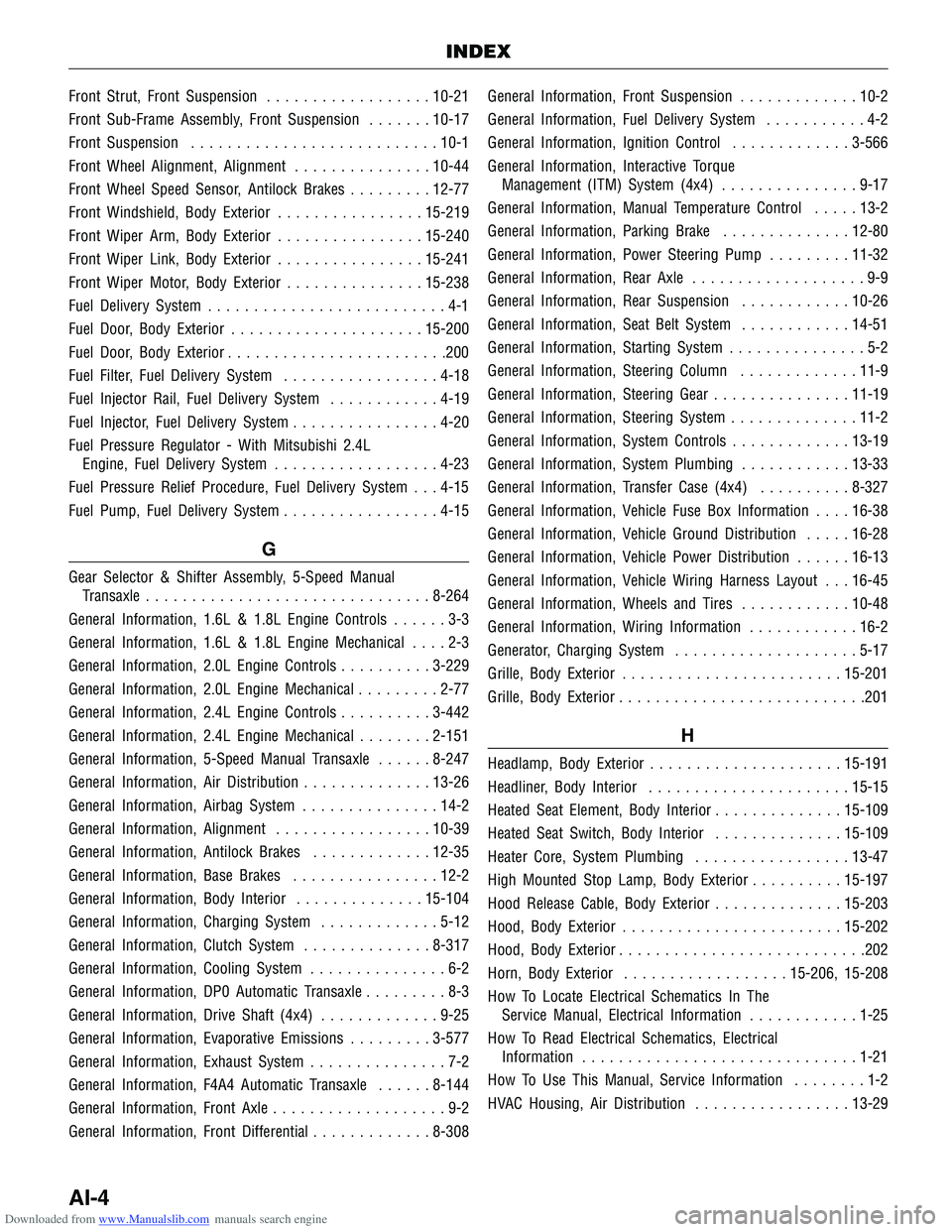
Downloaded from www.Manualslib.com manuals search engine Front Strut, Front Suspension..................10-21
Front Sub-Frame Assembly, Front Suspension .......10-17
Front Suspension ........................... 10-1
Front Wheel Alignment, Alignment ...............10-44
Front Wheel Speed Sensor, Antilock Brakes .........12-77
Front Windshield, Body Exterior ................15-219
Front Wiper Arm, Body Exterior ................15-240
Front Wiper Link, Body Exterior ................15-241
Front Wiper Motor, Body Exterior ...............15-238
Fuel Delivery System ..........................4-1
Fuel Door, Body Exterior ..................... 15-200
Fuel Door, Body Exterior ........................200
Fuel Filter, Fuel Delivery System .................4-18
Fuel Injector Rail, Fuel Delivery System ............4-19
Fuel Injector, Fuel Delivery System ................4-20
Fuel Pressure Regulator - With Mitsubishi 2.4L Engine, Fuel Delivery System ..................4-23
Fuel Pressure Relief Procedure, Fuel Delivery System . . . 4-15
Fuel Pump, Fuel Delivery System .................4-15
G
Gear Selector & Shifter Assembly, 5-Speed Manual
Transaxle ............................... 8-264
General Information, 1.6L & 1.8L Engine Controls ......3-3
General Information, 1.6L & 1.8L Engine Mechanical ....2-3
General Information, 2.0L Engine Controls ..........3-229
General Information, 2.0L Engine Mechanical .........2-77
General Information, 2.4L Engine Controls ..........3-442
General Information, 2.4L Engine Mechanical ........2-151
General Information, 5-Speed Manual Transaxle ......8-247
General Information, Air Distribution ..............13-26
General Information, Airbag System ...............14-2
General Information, Alignment .................10-39
General Information, Antilock Brakes .............12-35
General Information, Base Brakes ................12-2
General Information, Body Interior ..............15-104
General Information, Charging System .............5-12
General Information, Clutch System ..............8-317
General Information, Cooling System ...............6-2
General Information, DP0 Automatic Transaxle .........8-3
General Information, Drive Shaft (4x4) .............9-25
General Information, Evaporative Emissions .........3-577
General Information, Exhaust System ...............7-2
General Information, F4A4 Automatic Transaxle ......8-144
General Information, Front Axle ...................9-2
General Information, Front Differential .............8-308General Information, Front Suspension
.............10-2
General Information, Fuel Delivery System ...........4-2
General Information, Ignition Control .............3-566
General Information, Interactive Torque Management (ITM) System (4x4) ...............9-17
General Information, Manual Temperature Control .....13-2
General Information, Parking Brake ..............12-80
General Information, Power Steering Pump .........11-32
General Information, Rear Axle ...................9-9
General Information, Rear Suspension ............10-26
General Information, Seat Belt System ............14-51
General Information, Starting System ...............5-2
General Information, Steering Column .............11-9
General Information, Steering Gear ...............11-19
General Information, Steering System ..............11-2
General Information, System Controls .............13-19
General Information, System Plumbing ............13-33
General Information, T
ransfer Case (4x4)..........8-327
General Information, Vehicle Fuse Box Information ....16-38
General Information, Vehicle Ground Distribution .....16-28
General Information, Vehicle Power Distribution ......16-13
General Information, Vehicle Wiring Harness Layout . . . 16-45
General Information, Wheels and Tires ............10-48
General Information, Wiring Information ............16-2
Generator, Charging System ....................5-17
Grille, Body Exterior ........................ 15-201
Grille, Body Exterior ...........................201
H
Headlamp, Body Exterior ..................... 15-191
Headliner, Body Interior ...................... 15-15
Heated Seat Element, Body Interior ..............15-109
Heated Seat Switch, Body Interior ..............15-109
Heater Core, System Plumbing .................13-47
High Mounted Stop Lamp, Body Exterior ..........15-197
Hood Release Cable, Body Exterior ..............15-203
Hood, Body Exterior ........................ 15-202
Hood, Body Exterior ...........................202
Horn, Body Exterior .................. 15-206, 15-208
How To Locate Electrical Schematics In The Service Manual, Electrical Information ............1-25
How To Read Electrical Schematics, Electrical Information .............................. 1-21
How To Use This Manual, Service Information ........1-2
HVAC Housing, Air Distribution .................13-29
INDEX
AI-4
Page 1900 of 1903

Downloaded from www.Manualslib.com manuals search engine I
Idle Air Control (IAC) Motor, 2.4L Engine Controls....3-541
Idler Pulley, 1.6L & 1.8L Engine Mechanical .........2-45
Idler Pulley, 2.0L Engine Mechanical ..............2-119
Ignition Coil 1.6L & 1.8L & 2.0L, Ignition Control ....3-571
Ignition Coil 2.4L, Ignition Control ...............3-572
Ignition Control ............................ 3-565
Immobilizer Control Module, Body Interior . . . 15-110, 15-144
Input Shaft, 5-Speed Manual Transaxle ............8-278
Instrument Cluster, Body Interior ...........15-52, 15-84
Instrument Panel, Body Interior .................15-45
Intake Manifold, 1.6L & 1.8L Engine Mechanical ......2-43
Intake Manifold, 2.0L Engine Mechanical ...........2-117
Intake Manifold, 2.4L Engine Mechanical ...........2-201
Interactive Torque Management (ITM) Control Module, Interactive Torque Management (ITM) System
(4x4) .................................. 9-23
Interactive Torque Management (ITM) Controller, Interactive Torque Management (ITM) System (4x4) . . 9-21
Interactive Torque Management (ITM) System (4x4) ....9-16
Interior Lamps, Body Interior ..................15-85
International Symbols, Vehicle Information ..........1-13
K
Key Hole Lamp, Body Interior ..................15-92
Knock Sensor, 1.6L & 1.8L Engine Controls ........3-218
Knock Sensor, 2.0L Engine Controls ..............3-428
Knock Sensor, 2.4L Engine Controls ..............3-533
L
License Plate Lamp, Body Exterior ..............15-197
Liquid Line, System Plumbing ..................13-44
Lower Balance Shaft, 2.4L Engine Mechanical .......2-208
Lower Console, Body Interior ..................15-50
Luggage Rack, Body Exterior ..................15-204
Luggage Rack, Body Exterior .....................204
M
Manifold Absolute Pressure Sensor - 1.6L, 1.6L & 1.8L
Engine Controls .......................... 3-222
Manual Temperature Control ....................13-1
Manual Temperature Control Module, Manual Temperature Control ................................ 13-15
Manual Transaxle Assembly, 5-Speed Manual Transaxle ............................... 8-260
Manual Transaxle Unit Repair, 5-Speed Manual Transaxle ............................... 8-270
Master Cylinder - LHD, Base Brakes ..............12-11Master Cylinder - RHD, Base Brakes
.............12-12
Middle/Rear Courtesy/Dome Lamp, Body Interior .....15-91
Mirrors, Body Exterior ...................... 15-209
Muffler, Exhaust System ........................7-6
N
Negative Battery Cable, Starting System .............5-8
O
Oil Filter, 1.6L & 1.8L Engine Mechanical ...........2-46
Oil Filter, 2.0L Engine Mechanical ................2-119
Oil Filter, 2.4L Engine Mechanical ................2-212
Oil Pan, 1.6L & 1.8L Engine Mechanical ............2-47
Oil Pan, 2.0L Engine Mechanical ................2-120
Oil Pan, 2.4L Engine Mechanical ................2-213
Oil Pump, 1.6L & 1.8L Engine Mechanical ..........2-48
Oil Pump, 2.0L Engine Mechanical ...............2-121
Oil Pump, 2.4L Engine Mechanical ...............2-215
Oil Strainer, 1.6L & 1.8L Engine Mechanical .........2-49
Oil Strainer, 2.0L Engine Mechanical ..............2-122
Oil Strainer, 2.4L Engine Mechanical ..............2-216
On-Vehicle Service, 1.6L & 1.8L Engine Controls .....3-217
On-Vehicle Service, 1.6L & 1.8L Engine Mechanical ....2-17
On-Vehicle Service, 2.0L Engine Controls ..........3-427
On-Vehicle Service, 2.0L Engine Mechanical .........2-91
On-Vehicle Service, 2.4L Engine Controls ..........3-531
On-Vehicle Service, 2.4L Engine Mechanical ........2-167
On-Vehicle Service, 5-Speed Manual Transaxle .......8-260
On-Vehicle Service, Air Distribution ..............13-29
On-Vehicle Service, Airbag System ...............14-46
On-Vehicle Service, Alignment ..................10-44
On-Vehicle Service, Antilock Brakes ..............12-76
On-Vehicle Service, Base Brakes .................12-9
On-Vehicle Service, Body Exterior ...............15-229
On-Vehicle Service, Body Interior .....15-144, 15-44, 15-84
On-Vehicle Service, Charging System ..............5-17
On-Vehicle Service, Cooling System ...............6-13
On-Vehicle Service, DP0 Automatic Transaxle ........8-136
On-Vehicle Service, Drive Shaft (4x4) ..............9-27
On-Vehicle Service, Evaporative Emissions ..........3-584
On-Vehicle Service, Exhaust System ................7-5
On-Vehicle Service, F4A4 Automatic Transaxle .......8-240
On-Vehicle Service, Front Axle ...................9-5
On-Vehicle Service, Front Suspension ..............10-7
On-Vehicle Service, Fuel Delivery System ...........4-15
On-Vehicle Service, Ignition
Control .............. 3-571
INDEX
AI
AI-5