air filter CHERY TIGGO 2009 Service Owner's Manual
[x] Cancel search | Manufacturer: CHERY, Model Year: 2009, Model line: TIGGO, Model: CHERY TIGGO 2009Pages: 1903, PDF Size: 33.38 MB
Page 616 of 1903

Downloaded from www.Manualslib.com manuals search engine 7.CHECK FUEL PRESSURE
• Release fuel pressure to zero.
• Install fuel pressure gauge (2) and check fuel
pressure.
• Observe the following fuel pressures when testing (See Fuel Pressure Test in Section 04 Fuel Delivery).
FUEL PRESSURES
Key On 400 kPa (4.0 bar)
Key Off 380 kPa (3.8 bar) in 10 minutes
Engine Idle 400 kPa (4.0 bar )
- 420 kPa (4.2 bar)
Is the check result normal?
Ye s>>Go to step 9.
No
>>Go to the next step.
8.DETECT MALFUNCTIONING PART
• Check the following:
Fuel pump and circuit.
Fuel pressure regulator.
Fuel lines.
Fuel filter for clogging.
Is the check result normal?
Ye s>>If with the X-431, go to the next step.
If without the X-431, go to step 10.
No
>>Repair or Replace malfunctioning part.
DIAGNOSIS & TESTING
BESM030020
03–332Chery Automobile Co., Ltd.
Page 723 of 1903

Downloaded from www.Manualslib.com manuals search engine Electronic Throttle Control Actuator
Description
The throttle body is located on the intake manifold. It controls air into the intake manifold. The Electronic Throttle
Control Actuator consists of a throttle control motor and the throttle position sensor. The throttle control motor is
operated by the ECM and it opens and closes the throttle valve. The throttle position sensor detects the throttle valve
position.
Operation
Filtered air from the air cleaner enters the intake manifold through the throttle body. A throttle valve (plate) is used to
supply air for idle and driving conditions. The throttle position sensor is part the throttle body. The throttle position
sensor signal is used by the ECM to determine throttle position. The ECM controls the electronic throttle control to
meter air into the engine. This regulates engine power. The vehicle is in sense a “Drive by Wire” system.
Removal & Installation
1. Remove the engine cover.
2. Disconnect the negative battery cable.
3. Disconnect the electronic throttle control actuatorconnector.
4. Remove two hoses on electronic throttle control actuator.
5. Remove four electronic throttle control actuator mounting bolts.
(Tighten: Electronic throttle control actuator bolts to
10 N·m)
6. Remove the throttle control actuator carefully.
7. Installation is in the reverse order of removal.
ON-VEHICLE SERVICE
BESM030022
03
03–439Chery Automobile Co., Ltd.
Page 822 of 1903

Downloaded from www.Manualslib.com manuals search engine Throttle Control Actuator
Description
The throttle body is located on the intake manifold. The throttle body meters air into the intake manifold.
Throttle control actuator consists of throttle control valve, throttle position sensor, idle air control motor, etc.
Operation
Filtered air from the air cleaner enters the intake manifold through the throttle body. A throttle valve (plate) is used to
supply air for idle and driving conditions. The throttle position sensor is part the throttle body. The throttle position
sensor signal is used by the ECM to determine throttle position. The ECM controls the throttle control to meter air
into the engine. This regulates engine power. The vehicle is in sense a “Drive by Wire” system.
Removal & Installation
1. Remove the engine cover.
2. Disconnect the negative battery cable.
3. Disconnect the throttle position sensor and idle air control motor electrical connect on the throttle control actua-tor.
4. Remove the accelerator cable on the throttle control actuator.
5. Remove three hoses on the throttle control actuator.
6. Remove four throttle control actuator mounting bolts (1).
(Tighten: Throttle control actuator bolts to 10 N·m)
7. Remove the throttle control actuator and gasket carefully.
8. Installation is in the reverse order of removal.
NOTE :
Replace a new throttle control actuator gasket when installing.
ON-VEHICLE SERVICE
LTSM030010
03–538Chery Automobile Co., Ltd.
Page 834 of 1903
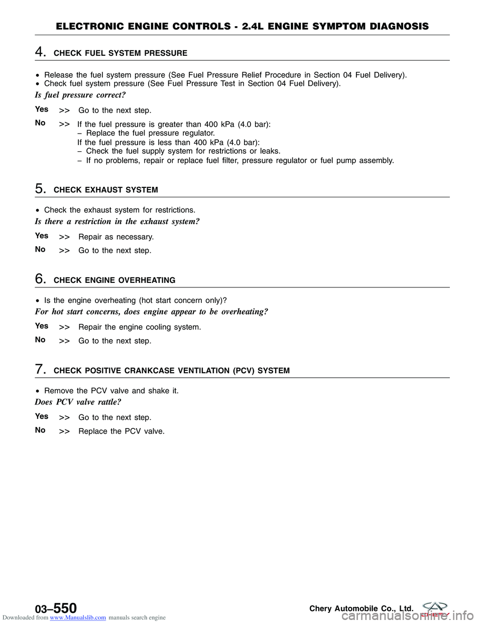
Downloaded from www.Manualslib.com manuals search engine 4.CHECK FUEL SYSTEM PRESSURE
• Release the fuel system pressure (See Fuel Pressure Relief Procedure in Section 04 Fuel Delivery).
• Check fuel system pressure (See Fuel Pressure Test in Section 04 Fuel Delivery).
Is fuel pressure correct?
Ye s>>Go to the next step.
No
>>If the fuel pressure is greater than 400 kPa (4.0 bar):
Replace the fuel pressure regulator.
If the fuel pressure is less than 400 kPa (4.0 bar):
Check the fuel supply system for restrictions or leaks.
If no problems, repair or replace fuel filter, pressure regulator or fuel pump assembly.
5.CHECK EXHAUST SYSTEM
• Check the exhaust system for restrictions.
Is there a restriction in the exhaust system?
Ye s>>Repair as necessary.
No
>>Go to the next step.
6.CHECK ENGINE OVERHEATING
• Is the engine overheating (hot start concern only)?
For hot start concerns, does engine appear to be overheating?
Ye s>>Repair the engine cooling system.
No
>>Go to the next step.
7.CHECK POSITIVE CRANKCASE VENTILATION (PCV) SYSTEM
• Remove the PCV valve and shake it.
Does PCV valve rattle?
Ye s>>Go to the next step.
No
>>Replace the PCV valve.
ELECTRONIC ENGINE CONTROLS - 2.4L ENGINE SYMPTOM DIAGNOSIS
03–550Chery Automobile Co., Ltd.
Page 837 of 1903

Downloaded from www.Manualslib.com manuals search engine Lack / Loss Of Power
The following conditions apply to this symptom:
•The engine has poor performance.
• The engine has poor acceleration.
1.PRELIMINARY CHECKS
• Verify symptom is reported under normal driving conditions without excessive engine/vehicle load conditions.
• Carry out the following preliminary checks:
Fuel quality
Vacuum lines (check for damage and correct routing)
Intake air system (check for damaged tubes and dirty air filter)
Vehicle wiring (disconnected, corroded/damaged)
Throttle linkage
Radiator (obstructed)
Transaxle
NOTE :
Be aware of the over RPM limiting functions of the ECM.
Are all checks OK?
Ye s>>Go to the next step.
No
>>Repair as necessary.
Verify the symptom no longer exists.
2.CHECK ECM DTC
• Turn ignition switch on.
• With the scan tool X-431, read the DTC.
Do any DTC displayed on the scan tool?
Ye s>>See the Diagnostic Trouble Code (DTC) List.
Go to the specific diagnostic test to troubleshoot the DTC.
No
>>Go to the next step.
3.CHECK FUEL SYSTEM PRESSURE
• Release the fuel system pressure (See Fuel Pressure Relief Procedure in Section 04 Fuel Delivery).
• Check fuel system pressure (See Fuel Pressure Test in Section 04 Fuel Delivery).
Is fuel pressure correct?
Ye s>>Go to the next step.
No
>>If the fuel pressure is greater than 400 kPa (4.0 bar):
Replace the fuel pressure regulator.
If the fuel pressure is less than 400 kPa (4.0 bar):
Check the fuel supply system for restrictions or leaks.
If no problems, repair or replace fuel filter, pressure regulator or fuel pump assembly.
ELECTRONIC ENGINE CONTROLS - 2.4L ENGINE SYMPTOM DIAGNOSIS
03
03–553Chery Automobile Co., Ltd.
Page 841 of 1903

Downloaded from www.Manualslib.com manuals search engine 5.CHECK KNOCK SENSOR
• Check knock sensor.
Is the check result normal?
Ye s>>Go to the next step.
No
>>Repair as necessary.
Verify the symptom no longer exists.
6.CHECK TIMING
• Check for the timing misalignment.
Is the check result normal?
Ye s>>Go to the next step.
No
>>Align the engine timing belt (See Engine Timing Belt Removal & Installation in Section 02 Engine).
7.CHECK FUEL SYSTEM PRESSURE
• Release the fuel system pressure (See Fuel Pressure Relief Procedure in Section 04 Fuel Delivery).
• Check fuel system pressure (See Fuel Pressure Test in Section 04 Fuel Delivery).
Is fuel pressure correct?
Ye s>>Go to the next step.
No
>>If the fuel pressure is greater than 400 kPa (4.0 bar):
Replace the fuel pressure regulator.
If the fuel pressure is less than 400 kPa (4.0 bar):
Check the fuel supply system for restrictions or leaks.
If no problems, repair or replace fuel filter, pressure regulator or fuel pump assembly.
8.CHECK FOR BASE ENGINE CONCERNS
• Check for base engine concerns (such as improper cylinder compression, worn camshaft/valve train, gasket
leaks).
Is a fault indicated?
Ye s>>Repair as necessary.
No
>>See Diagnostic Help for additional information.
ELECTRONIC ENGINE CONTROLS - 2.4L ENGINE SYMPTOM DIAGNOSIS
03
03–557Chery Automobile Co., Ltd.
Page 842 of 1903

Downloaded from www.Manualslib.com manuals search engine Engine Poor Driveability
The following conditions apply to this symptom:
•Engine stalls/quits, engine runs rough, misses, buck/jerk, hesitation/stumble acceleration, surges, rolling idle.
• Engine stops unexpectedly at beginning of acceleration or during acceleration.
• Engine stops unexpectedly while cruising.
• Engine speed fluctuates during acceleration.
• Engine misses during acceleration.
• Vehicle bucks/jerks during acceleration, cruising or deceleration.
• Momentary pause during acceleration.
• Momentary minor loss in engine output.
1.PRELIMINARY CHECKS
NOTE :
Be aware of the over RPM limiting functions of the ECM.
• Carry out the following preliminary checks:
Fuel quality
Vacuum lines (check for damage and correct routing)
Intake air system (check for damaged tubes and dirty air filter)
Vehicle wiring (disconnected, corroded/damaged)
Throttle linkage.
Radiator (obstructed)
Transaxle
Are all checks OK?
Ye s>>Go to the next step.
No
>>Repair as necessary.
Verify the symptom no longer exists.
2.CHECK FOR STALL AT IDLE
• Check for engine stall at idle.
NOTE :
Confirm that proper vehicle maintenance has been performed before continuing with engine diagnosis.
• Inspect the following components:
Clean the injectors
Fuel filter
Intake air filter
Throttle body
Spark plugs
Spark plug wires
Does the engine now stall at idle?
Ye s>>Repair as necessary.
No
>>Go to the next step.
ELECTRONIC ENGINE CONTROLS - 2.4L ENGINE SYMPTOM DIAGNOSIS
03–558Chery Automobile Co., Ltd.
Page 844 of 1903

Downloaded from www.Manualslib.com manuals search engine 6.CHECK SECONDARY IGNITION SYSTEM
• Perform the following to test the secondary ignition system:
Disconnect the injector fuse.
Remove any of the 4 spark plugs.
Connect the spark plug to spark plug wire.
Ground the spark plug on the cylinder block.
Crank the engine to test the secondary ignition system with the spark plugs removed.
Is a strong blue spark visible at each spark plug while cranking the engine?
Ye s>>Go to the next step.
No
>>Check Camshaft Position (CMP) sensor signal at ECM.
If CMP sensor is OK, check the following:
Crankshaft Position (CKP) sensor malfunction
Spark plug wires
Spark plugs
7.CHECK FUEL SYSTEM PRESSURE
• Release the fuel system pressure (See Fuel Pressure Relief Procedure in Section 04 Fuel Delivery).
• Check fuel system pressure (See Fuel Pressure Test in Section 04 Fuel Delivery).
Is fuel pressure correct?
Ye s>>Go to the next step.
No
>>If the fuel pressure is greater than 400 kPa (4.0 bar):
Replace the fuel pressure regulator.
If the fuel pressure is less than 400 kPa (4.0 bar):
Check the fuel supply system for restrictions or leaks.
If no problems, repair or replace fuel filter, pressure regulator or fuel pump assembly.
8.CHECK EXHAUST SYSTEM
• Check the exhaust system for restrictions.
Is there a restriction in the exhaust system?
Ye s>>Repair as necessary.
No
>>Go to the next step.
9.CHECK PCV SYSTEM
• Check the Positive Crankcase Ventilation (PCV) system.
• Remove PCV valve and shake it.
Is PCV valve normal?
Ye s>>Go to the next step.
No
>>Replace the PCV valve.
ELECTRONIC ENGINE CONTROLS - 2.4L ENGINE SYMPTOM DIAGNOSIS
03–560Chery Automobile Co., Ltd.
Page 847 of 1903

Downloaded from www.Manualslib.com manuals search engine 5.CHECK CLUTCH OPERATION CONDITION
• Check clutch operation condition.
Is the transaxle clutch operation normal?
Ye s>>Go to the next step.
No
>>Repair as necessary.
6.CHECK A/C SYSTEM OPERATION
• Start engine.
• Cycle A/C switch from on to off (verify A/C clutch engages condition).
• Check the A/C system operation.
Does the A/C system operate normally?
Ye s>>Go to the next step.
No
>>Repair as necessary.
7.CHECK FUEL SYSTEM PRESSURE
• Release the fuel system pressure (See Fuel Pressure Relief Procedure in Section 04 Fuel Delivery).
• Check fuel system pressure (See Fuel Pressure Test in Section 04 Fuel Delivery).
Is fuel pressure correct?
Ye s>>Go to the next step.
No
>>If the fuel pressure is greater than 400 kPa (4.0 bar):
Replace the fuel pressure regulator.
If the fuel pressure is less than 400 kPa (4.0 bar):
Check the fuel supply system for restrictions or leaks.
If no problems, repair or replace fuel filter, pressure regulator or fuel pump assembly.
8.CHECK FOR BASE ENGINE CONCERNS
• Check for base engine concerns (such as improper compression, worn camshaft/valve train, gasket leaks).
Is a fault indicated?
Ye s>>Repair as necessary.
No
>>See Diagnostic Help for additional information.
ELECTRONIC ENGINE CONTROLS - 2.4L ENGINE SYMPTOM DIAGNOSIS
03
03–563Chery Automobile Co., Ltd.
Page 861 of 1903

Downloaded from www.Manualslib.com manuals search engine GENERAL INFORMATION
Description
The evaporation control system prevents the emission of fuel tank vapors into the atmosphere. When fuel evaporates
in the fuel tank, the vapors pass through vent hoses or tubes to an activated carbon filled evaporative canister. The
canister temporarily holds the vapors. The Engine Control Module (ECM) allows intake manifold vacuum to draw
vapors into the combustion chambers during certain operating conditions.
Operation
1.6L / 1.8L / 2.0L
1-Fuel Tank2-Fuel Vapor
3-Canister 4-Air Intake
5-Hose 6-Canister Control Valve7-Throttle Valve8-Air Filter Assembly
9-To Engine 10-Air Intake
BESM030026
03
03–577Chery Automobile Co., Ltd.