compression ratio CHERY TIGGO 2009 Service Repair Manual
[x] Cancel search | Manufacturer: CHERY, Model Year: 2009, Model line: TIGGO, Model: CHERY TIGGO 2009Pages: 1903, PDF Size: 33.38 MB
Page 30 of 1903
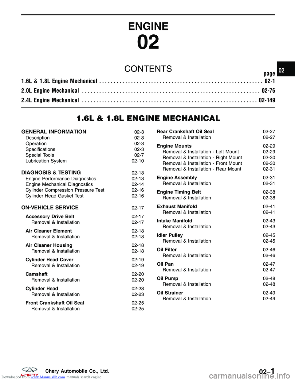
Downloaded from www.Manualslib.com manuals search engine ENGINE
02
CONTENTSpage
1.6L & 1.8L Engine Mechanical ......................................................... 02-1
2.0L Engine Mechanical .............................................................. 02-76
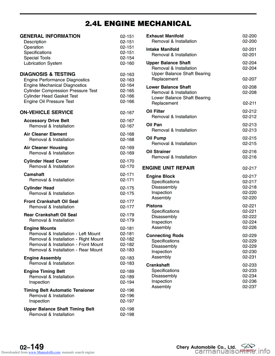
2.4L Engine Mechanical ............................................................. 02-149
1.6L & 1.8L ENGINE MECHANICAL
GENERAL INFORMATION02-3
Description 02-3
Operation 02-3
Specifications 02-3
Special Tools 02-7
Lubrication System 02-10
DIAGNOSIS & TESTING02-13
Engine Performance Diagnostics 02-13
Engine Mechanical Diagnostics 02-14
Cylinder Compression Pressure Test 02-16
Cylinder Head Gasket Test 02-16
ON-VEHICLE SERVICE02-17
Accessory Drive Belt 02-17
Removal & Installation 02-17
Air Cleaner Element 02-18
Removal & Installation 02-18
Air Cleaner Housing 02-18
Removal & Installation 02-18
Cylinder Head Cover 02-19
Removal & Installation 02-19
Camshaft 02-20
Removal & Installation 02-20
Cylinder Head 02-23
Removal & Installation 02-23
Front Crankshaft Oil Seal 02-25
Removal & Installation 02-25 Rear Crankshaft Oil Seal
02-27
Removal & Installation 02-27
Engine Mounts 02-29
Removal & Installation - Left Mount 02-29
Removal & Installation - Right Mount 02-30
Removal & Installation - Front Mount 02-30
Removal & Installation - Rear Mount 02-31
Engine Assembly 02-31
Removal & Installation 02-31
Engine Timing Belt 02-38
Removal & Installation 02-38
Exhaust Manifold 02-41
Removal & Installation 02-41
Intake Manifold 02-43
Removal & Installation 02-43
Idler Pulley 02-45
Removal & Installation 02-45
Oil Filter 02-46
Removal & Installation 02-46
Oil Pan 02-47
Removal & Installation 02-47
Oil Pump 02-48
Removal & Installation 02-48
Oil Strainer 02-49
Removal & Installation 02-49
02
02–1Chery Automobile Co., Ltd.
Page 32 of 1903
Downloaded from www.Manualslib.com manuals search engine GENERAL INFORMATION
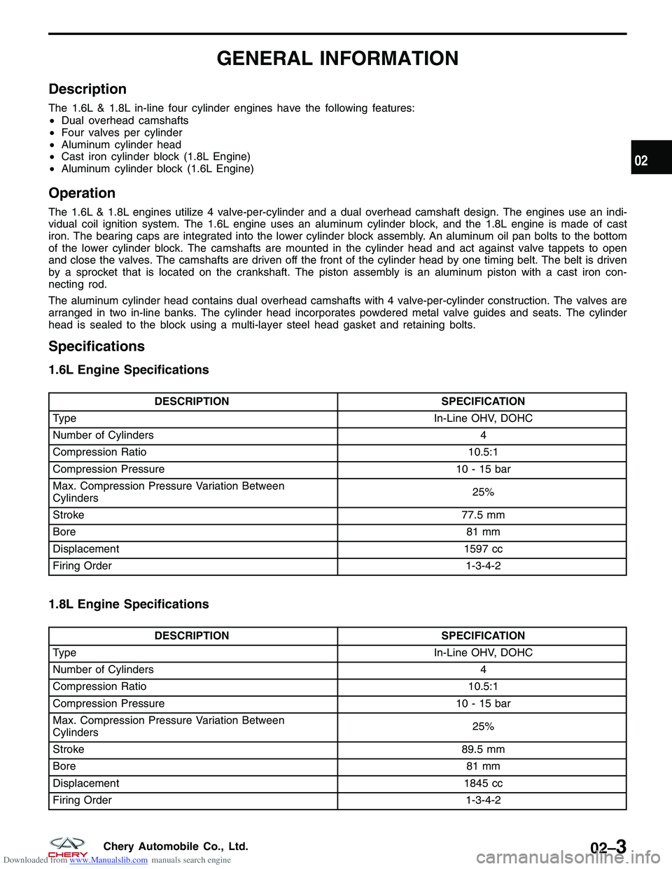
Description
The 1.6L & 1.8L in-line four cylinder engines have the following features:
•Dual overhead camshafts
• Four valves per cylinder
• Aluminum cylinder head
• Cast iron cylinder block (1.8L Engine)
• Aluminum cylinder block (1.6L Engine)
Operation
The 1.6L & 1.8L engines utilize 4 valve-per-cylinder and a dual overhead camshaft design. The engines use an indi-
vidual coil ignition system. The 1.6L engine uses an aluminum cylinder block, and the 1.8L engine is made of cast
iron. The bearing caps are integrated into the lower cylinder block assembly. An aluminum oil pan bolts to the bottom
of the lower cylinder block. The camshafts are mounted in the cylinder head and act against valve tappets to open
and close the valves. The camshafts are driven off the front of the cylinder head by one timing belt. The belt is driven
by a sprocket that is located on the crankshaft. The piston assembly is an aluminum piston with a cast iron con-
necting rod.
The aluminum cylinder head contains dual overhead camshafts with 4 valve-per-cylinder construction. The valves are
arranged in two in-line banks. The cylinder head incorporates powdered metal valve guides and seats. The cylinder
head is sealed to the block using a multi-layer steel head gasket and retaining bolts.
Specifications
1.6L Engine Specifications
DESCRIPTION SPECIFICATION
Type In-Line OHV, DOHC
Number of Cylinders 4
Compression Ratio 10.5:1
Compression Pressure 10 - 15 bar
Max. Compression Pressure Variation Between
Cylinders 25%
Stroke 77.5 mm
Bore 81 mm
Displacement 1597 cc
Firing Order 1-3-4-2
1.8L Engine Specifications
DESCRIPTIONSPECIFICATION
Type In-Line OHV, DOHC
Number of Cylinders 4
Compression Ratio 10.5:1
Compression Pressure 10 - 15 bar
Max. Compression Pressure Variation Between
Cylinders 25%
Stroke 89.5 mm
Bore 81 mm
Displacement 1845 cc
Firing Order 1-3-4-2
02
02–3Chery Automobile Co., Ltd.
Page 105 of 1903
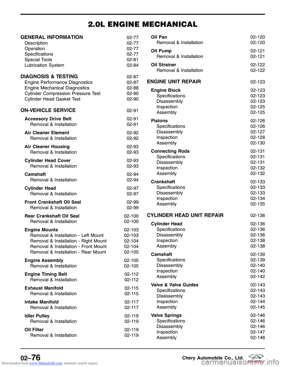
Downloaded from www.Manualslib.com manuals search engine 2.0L ENGINE MECHANICAL
GENERAL INFORMATION02-77
Description 02-77
Operation 02-77
Specifications 02-77
Special Tools 02-81
Lubrication System 02-84
DIAGNOSIS & TESTING02-87
Engine Performance Diagnostics 02-87
Engine Mechanical Diagnostics 02-88
Cylinder Compression Pressure Test 02-90
Cylinder Head Gasket Test 02-90
ON-VEHICLE SERVICE02-91
Accessory Drive Belt 02-91
Removal & Installation 02-91
Air Cleaner Element 02-92
Removal & Installation 02-92
Air Cleaner Housing 02-93
Removal & Installation 02-93
Cylinder Head Cover 02-93
Removal & Installation 02-93
Camshaft 02-94
Removal & Installation 02-94
Cylinder Head 02-97
Removal & Installation 02-97
Front Crankshaft Oil Seal 02-99
Removal & Installation 02-99
Rear Crankshaft Oil Seal 02-100
Removal & Installation 02-100
Engine Mounts 02-103
Removal & Installation - Left Mount 02-103
Removal & Installation - Right Mount 02-104
Removal & Installation - Front Mount 02-104
Removal & Installation - Rear Mount 02-105
Engine Assembly 02-105
Removal & Installation 02-105
Engine Timing Belt 02-112
Removal & Installation 02-112
Exhaust Manifold 02-115
Removal & Installation 02-115
Intake Manifold 02-117
Removal & Installation 02-117
Idler Pulley 02-119
Removal & Installation 02-119
Oil Filter 02-119
Removal & Installation 02-119Oil Pan
02-120
Removal & Installation 02-120
Oil Pump 02-121
Removal & Installation 02-121
Oil Strainer 02-122
Removal & Installation 02-122
ENGINE UNIT REPAIR02-123
Engine Block 02-123
Specifications 02-123
Disassembly 02-123
Inspection 02-125
Assembly 02-125
Pistons 02-126
Specifications 02-126
Disassembly 02-127
Inspection 02-128
Assembly 02-130
Connecting Rods 02-131
Specifications 02-131
Disassembly 02-131
Inspection 02-132
Assembly 02-132
Crankshaft 02-133
Specifications 02-133
Disassembly 02-133
Inspection 02-134
Assembly 02-135
CYLINDER HEAD UNIT REPAIR02-136
Cylinder Head 02-136
Specifications 02-136
Disassembly 02-136
Inspection 02-138
Assembly 02-138
Camshaft 02-139
Specifications 02-139
Disassembly 02-140
Inspection 02-140
Assembly 02-142
Valve & Valve Guides 02-143
Specifications 02-143
Disassembly 02-143
Inspection 02-144
Assembly 02-145
Valve Springs 02-146
Specifications 02-146
Disassembly 02-146
Inspection 02-147
Assembly 02-148
02–76Chery Automobile Co., Ltd.
Page 106 of 1903
Downloaded from www.Manualslib.com manuals search engine GENERAL INFORMATION
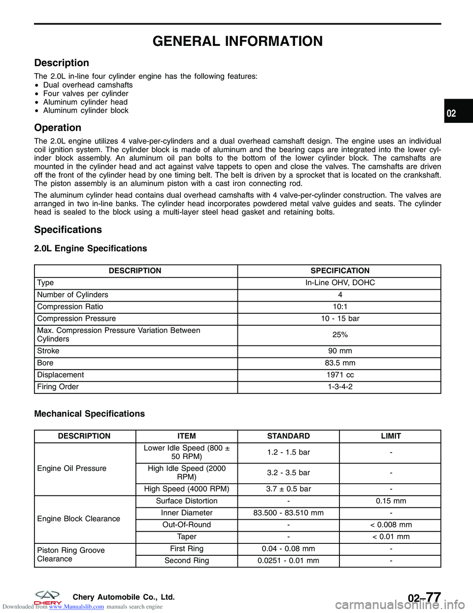
Description
The 2.0L in-line four cylinder engine has the following features:
•Dual overhead camshafts
• Four valves per cylinder
• Aluminum cylinder head
• Aluminum cylinder block
Operation
The 2.0L engine utilizes 4 valve-per-cylinders and a dual overhead camshaft design. The engine uses an individual
coil ignition system. The cylinder block is made of aluminum and the bearing caps are integrated into the lower cyl-
inder block assembly. An aluminum oil pan bolts to the bottom of the lower cylinder block. The camshafts are
mounted in the cylinder head and act against valve tappets to open and close the valves. The camshafts are driven
off the front of the cylinder head by one timing belt. The belt is driven by a sprocket that is located on the crankshaft.
The piston assembly is an aluminum piston with a cast iron connecting rod.
The aluminum cylinder head contains dual overhead camshafts with 4 valve-per-cylinder construction. The valves are
arranged in two in-line banks. The cylinder head incorporates powdered metal valve guides and seats. The cylinder
head is sealed to the block using a multi-layer steel head gasket and retaining bolts.
Specifications
2.0L Engine Specifications
DESCRIPTION SPECIFICATION
Type In-Line OHV, DOHC
Number of Cylinders 4
Compression Ratio 10:1
Compression Pressure 10 - 15 bar
Max. Compression Pressure Variation Between
Cylinders 25%
Stroke 90 mm
Bore 83.5 mm
Displacement 1971 cc
Firing Order 1-3-4-2
Mechanical Specifications
DESCRIPTIONITEMSTANDARD LIMIT
Engine Oil Pressure Lower Idle Speed (800 ±
50 RPM) 1.2 - 1.5 bar
-
High Idle Speed (2000 RPM) 3.2 - 3.5 bar
-
High Speed (4000 RPM) 3.7 ± 0.5 bar -
Engine Block Clearance Surface Distortion
-0.15 mm
Inner Diameter 83.500 - 83.510 mm -
Out-Of-Round -< 0.008 mm
Taper -< 0.01 mm
Piston Ring Groove
Clearance First Ring
0.04 - 0.08 mm -
Second Ring 0.0251 - 0.01 mm -
02
02–77Chery Automobile Co., Ltd.
Page 178 of 1903
Downloaded from www.Manualslib.com manuals search engine 2.4L ENGINE MECHANICAL
GENERAL INFORMATION02-151
Description 02-151
Operation 02-151
Specifications 02-151
Special Tools 02-154
Lubrication System 02-160
DIAGNOSIS & TESTING02-163
Engine Performance Diagnostics 02-163
Engine Mechanical Diagnostics 02-164
Cylinder Compression Pressure Test 02-165
Cylinder Head Gasket Test 02-166
Engine Oil Pressure Test 02-166
ON-VEHICLE SERVICE02-167
Accessory Drive Belt 02-167
Removal & Installation 02-167
Air Cleaner Element 02-168
Removal & Installation 02-168
Air Cleaner Housing 02-169
Removal & Installation 02-169
Cylinder Head Cover 02-170
Removal & Installation 02-170
Camshaft 02-171
Removal & Installation 02-171
Cylinder Head 02-175
Removal & Installation 02-175
Front Crankshaft Oil Seal 02-177
Removal & Installation 02-177
Rear Crankshaft Oil Seal 02-179
Removal & Installation 02-179
Engine Mounts 02-181
Removal & Installation - Left Mount 02-181
Removal & Installation - Right Mount 02-182
Removal & Installation - Front Mount 02-182
Removal & Installation - Rear Mount 02-183
Engine Assembly 02-183
Removal & Installation 02-183
Engine Timing Belt 02-189
Removal & Installation 02-189
Inspection 02-194
Timing Belt Automatic Tensioner 02-196
Removal & Installation 02-196
Inspection 02-197
Upper Balance Shaft Timing Belt 02-198
Removal & Installation 02-198Exhaust Manifold
02-200
Removal & Installation 02-200
Intake Manifold 02-201
Removal & Installation 02-201
Upper Balance Shaft 02-204
Removal & Installation 02-204
Upper Balance Shaft Bearing
Replacement 02-207
Lower Balance Shaft 02-208
Removal & Installation 02-208
Lower Balance Shaft Bearing
Replacement 02-211
Oil Filter 02-212
Removal & Installation 02-212
Oil Pan 02-213
Removal & Installation 02-213
Oil Pump 02-215
Removal & Installation 02-215
Oil Strainer 02-216
Removal & Installation 02-216
ENGINE UNIT REPAIR02-217
Engine Block 02-217
Specifications 02-217
Disassembly 02-218
Inspection 02-220
Assembly 02-220
Pistons 02-221
Specifications 02-221
Disassembly 02-222
Inspection 02-224
Assembly 02-226
Connecting Rods 02-229
Specifications 02-229
Disassembly 02-229
Inspection 02-230
Assembly 02-231
Crankshaft 02-233
Specifications 02-233
Disassembly 02-234
Inspection 02-236
Assembly 02-237
02–149Chery Automobile Co., Ltd.
Page 180 of 1903
Downloaded from www.Manualslib.com manuals search engine GENERAL INFORMATION
Description
The 2.4L in-line four cylinder engine has the following features:
•Single overhead camshaft
• Four valves per chamber cylinder head design
• Aluminum cylinder head
• Cast iron cylinder block
Operation
The 2.4L engine utilizes 4 valves-per-cylinder and a single-overhead-camshaft design. The engine uses an individual
coil ignition system and multi-point sequential injection. The cylinder block is made of cast iron and the bearing caps
are integrated into the lower cylinder block assembly. A cast iron oil pan is located at the bottom of the lower cylinder
block. The camshaft is mounted in the cylinder head and acts against the valve tappets to open and close the valves.
The camshaft is driven off the front of the cylinder head by the timing belt. The belt is driven by a sprocket that is
located on the crankshaft. The piston assembly is an aluminum piston with a cast iron connecting rod.
The aluminum cylinder head contains a single overhead camshaft with 4 valves-per-cylinder construction. The valves
are arranged in two in-line banks. The cylinder head incorporates powdered metal valve guides and seats. The cyl-
inder head is sealed to the block using a multi-layer steel head gasket and retaining bolts.
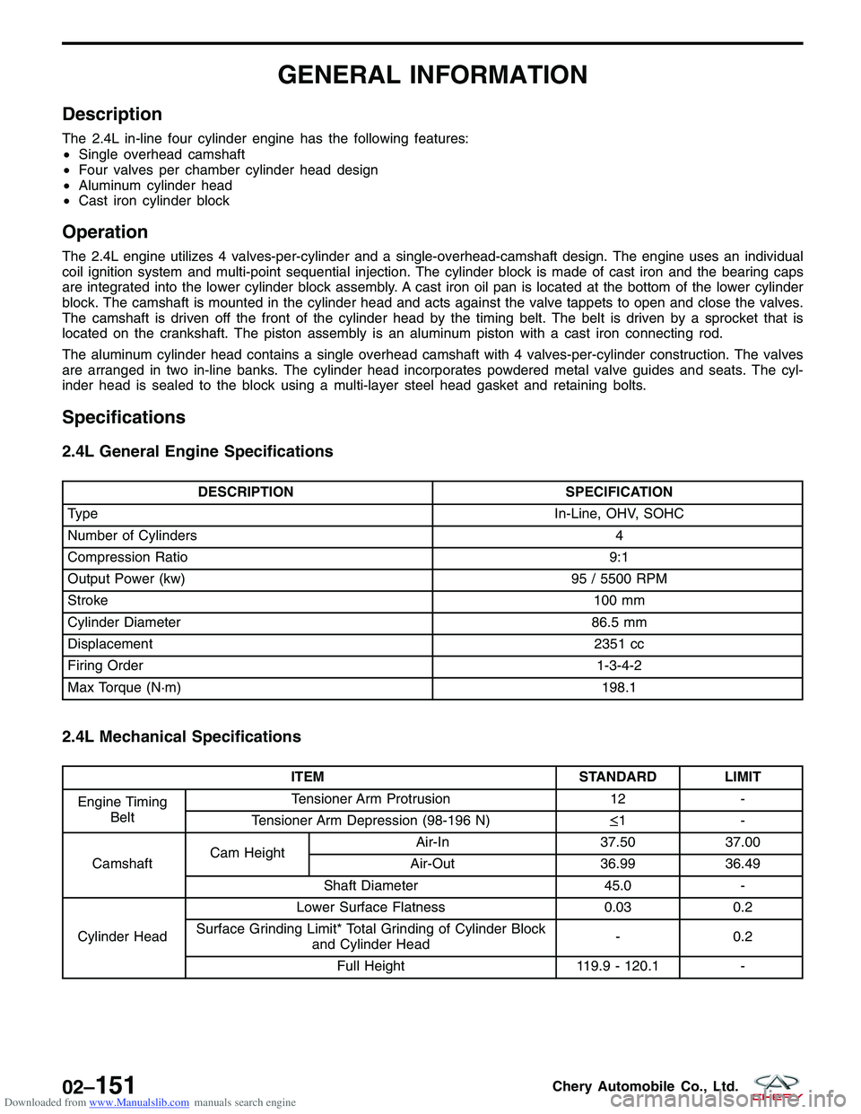
Specifications
2.4L General Engine Specifications
DESCRIPTION SPECIFICATION
Type In-Line, OHV, SOHC
Number of Cylinders 4
Compression Ratio 9:1
Output Power (kw) 95 / 5500 RPM
Stroke 100 mm
Cylinder Diameter 86.5 mm
Displacement 2351 cc
Firing Order 1-3-4-2
Max Torque (N·m) 198.1
2.4L Mechanical Specifications
ITEMSTANDARD LIMIT
Engine Timing Belt Tensioner Arm Protrusion
12-
Tensioner Arm Depression (98-196 N) ≤1-
Camshaft Cam Height Air-In
37.5037.00
Air-Out 36.9936.49
Shaft Diameter 45.0-
Cylinder Head Lower Surface Flatness
0.030.2
Surface Grinding Limit* Total Grinding of Cylinder Block and Cylinder Head -
0.2
Full Height 119.9 - 120.1-
02–151Chery Automobile Co., Ltd.
Page 828 of 1903

Downloaded from www.Manualslib.com manuals search engine Symptom Diagnostic Tests
General Troubleshooting Checks
•Confirm the engine trouble light is working properly.
• Confirm that there are no DTCs recorded with the X-431 Scan Tool.
• Confirm that the customer’s complaint is current, and the conditions that are causing the failure are present.
Visual Inspection
•Check the fuel system for any fuel leakage.
• Check the vacuum system for any broken, kinked or incorrectly linked vacuum pipes or hoses.
• Check the intake air pipe for being jammed, leaking, or damaged.
• Check the ignition system for any broken or aging spark plug wires and verify the engine firing order is correct.
• Check the engine ground cable and verify a clean and tight connection.
• Check the sensors and actuators electrical connectors and verify good contact and tight connection.
NOTE :
Repair any of the above conditions first before continuing with symptom diagnostics.
Diagnostic Help
• Confirm there are no current engine DTCs.
• Confirm that the failure exists and the customer complaint can be verified.
• Inspect the engine following the above steps and verify all engine features are operating properly.
• While servicing the vehicle, verify the service record, vehicle maintenance, engine compression pressures,
mechanical ignition timing and fuel conditions.
• If replacing the Engine Control Module (ECM), carry out the validation test. If the failure no longer exists, the
failure is in the ECM; if the failure still exists, reinstall the original ECM and repeat the diagnostic test.
Symptom Diagnostic Test List
SYMPTOM DEFINITION
Engine Cranks Normal But Will Not Start
Engine Will Not Crank
Hard Start / Long Crank Time
Fast Idle
Lack / Loss Of Power
Back Fires
Engine Poor Driveability
Low Idle / Stalls During Deceleration
Idle Speed Slow Return To Normal Idle
ELECTRONIC ENGINE CONTROLS - 2.4L ENGINE SYMPTOM DIAGNOSIS
03–544Chery Automobile Co., Ltd.
Page 838 of 1903

Downloaded from www.Manualslib.com manuals search engine 4.CHECK SECONDARY IGNITION SYSTEM
• Perform the following to test the secondary ignition system:
� Disconnect the injector fuse.
� Remove any of the 4 spark plugs.
� Connect the spark plug to spark plug wire.
� Ground the spark plug on the cylinder block.
� Crank the engine to test the secondary ignition system with the spark plugs removed.
Is a strong blue spark visible at each spark plug while cranking the engine?
Ye s>>Go to the next step.
No
>>Check Camshaft Position (CMP) sensor signal at ECM.
If CMP sensor is OK, check the following:
� Crankshaft Position (CKP) sensor malfunction
� Spark plug wires
� Spark plugs
5.CHECK INTAKE AIR SYSTEM
• Check for MAP/MAF sensor.
Is there any contamination?
Ye s>>Clean or replace the sensor.
No
>>Go to the next step.
6.CHECK EXHAUST SYSTEM
• Check the exhaust system for restrictions.
Is there a restriction in the exhaust system?
Ye s>>Repair as necessary.
No
>>Go to the next step.
7.CHECK BASE ENGINE CONCERNS
• Check for base engine concerns (such as improper compression, worn camshaft/valve train, gasket leaks).
Is a fault indicated?
Ye s>>Repair as necessary.
No
>>Go to the next step.
8.CHECK AUTOMATIC/MANUAL TRANSAXLE OPERATION
• Check the operation of the transaxle.
Is the transaxle operation normal?
Ye s>>Go to the next step.
No
>>Repair as necessary.
ELECTRONIC ENGINE CONTROLS - 2.4L ENGINE SYMPTOM DIAGNOSIS
03–554Chery Automobile Co., Ltd.
Page 847 of 1903

Downloaded from www.Manualslib.com manuals search engine 5.CHECK CLUTCH OPERATION CONDITION
• Check clutch operation condition.
Is the transaxle clutch operation normal?
Ye s>>Go to the next step.
No
>>Repair as necessary.
6.CHECK A/C SYSTEM OPERATION
• Start engine.
• Cycle A/C switch from on to off (verify A/C clutch engages condition).
• Check the A/C system operation.
Does the A/C system operate normally?
Ye s>>Go to the next step.
No
>>Repair as necessary.
7.CHECK FUEL SYSTEM PRESSURE
• Release the fuel system pressure (See Fuel Pressure Relief Procedure in Section 04 Fuel Delivery).
• Check fuel system pressure (See Fuel Pressure Test in Section 04 Fuel Delivery).
Is fuel pressure correct?
Ye s>>Go to the next step.
No
>>If the fuel pressure is greater than 400 kPa (4.0 bar):
� Replace the fuel pressure regulator.
If the fuel pressure is less than 400 kPa (4.0 bar):
� Check the fuel supply system for restrictions or leaks.
� If no problems, repair or replace fuel filter, pressure regulator or fuel pump assembly.
8.CHECK FOR BASE ENGINE CONCERNS
• Check for base engine concerns (such as improper compression, worn camshaft/valve train, gasket leaks).
Is a fault indicated?
Ye s>>Repair as necessary.
No
>>See Diagnostic Help for additional information.
ELECTRONIC ENGINE CONTROLS - 2.4L ENGINE SYMPTOM DIAGNOSIS
03
03–563Chery Automobile Co., Ltd.