differential CHERY TIGGO 2009 Service Repair Manual
[x] Cancel search | Manufacturer: CHERY, Model Year: 2009, Model line: TIGGO, Model: CHERY TIGGO 2009Pages: 1903, PDF Size: 33.38 MB
Page 944 of 1903

Downloaded from www.Manualslib.com manuals search engine TRANSAXLE & TRANSFER CASE
08
CONTENTSpage
DP0 Automatic Transaxle .............................................................. 08-1
F4A4 Automatic Transaxle ........................................................... 08-143
5-Speed Manual Transaxle ........................................................... 08-246
Front Differential ................................................................... 08-307
Clutch System ..................................................................... 08-316
Transfer Case (4x4) ................................................................. 08-326
DP0 AUTOMATIC TRANSAXLE
GENERAL INFORMATION08-3
Description 08-3
Operation 08-6
Specifications 08-7
Special Tools 08-8
Electrical Schematics 08-10
DP0 Transaxle Control Module (TCM)
Connector Pin-Out Table 08-18
DIAGNOSIS & TESTING08-19
Diagnostic Help 08-19
Intermittent DTC Troubleshooting 08-19
Ground Inspection 08-19
Diagnostic Tools 08-19
Diagnostic Trouble Code (DTC) List 08-20
DP0 Automatic Transaxle DTC List 08-20
Diagnostic Trouble Code (DTC) Tests 08-22
P0641 - Sensor Feed 08-22
P0657 - Solenoid Power Supply Circuit
Shorted To Voltage 08-28
P0657 - Solenoid Power Supply Circuit
Open 08-32
P0705 - Multi-Function Switch:
Prohibited Position 08-37
P0710 - Fluid Temperature Sensor 08-42
P0715 - Turbine Speed Sensor Affected
By Interference 08-46
P0730 - Ratio Of Transaxle Error 08-50
P0753 - Shift Solenoid Valve 1 (SSV1)
Open Circuit Or Short To Power Supply
Or Short To Ground 08-56 P0758 - Shift Solenoid Valve 2 (SSV2)
Open Circuit Or Short To Power Supply
Or Short To Ground 08-62
P0763 - Shift Solenoid Valve 3 (SSV3)
Short To Power Supply, P0763 - Shift
Solenoid Valve 3 (SSV3) Open Or
Short To Ground Circuit 08-68
P0768 - Shift Solenoid Valve 4 (SSV4)
Short To Power Supply, P0768 - Shift
Solenoid Valve 4 (SSV4) Open Or
Short To Ground Circuit 08-74
P0773 - Shift Solenoid Valve 5 (SSV5)
Short To Power Supply, P0773 - Shift
Solenoid Valve 5 (SSV5) Open Or
Short To Ground Circuit 08-81
P0775 - EVM (Modulation Solenoid
Valve) Open Circuit Or Short To
Ground, P0775 - EVM (Modulation
Solenoid Valve) Shorted To Voltage 08-87
P0795 - Torque Converter Lock
Solenoid Valve (EVLU) Open Circuit Or
Short To Ground, P0795 - Torque
Converter Lock Solenoid Valve (EVLU)
Short To Voltage 08-93
P0840 - Pressure Sensor 08-99
P1928 - Shift Lock Solenoid Valve
Circuit Shorted To Voltage 08-104
P1928 - Shift Lock Solenoid Valve
Open Circuit Or Short To Ground 08-109
P2709 - Shift Solenoid Valve 6 (SSV6)
Short To Power Supply 08-114
P2709 - Shift Solenoid Valve 6 (SSV6)
Open Circuit Or Short To Ground 08-119
08
08–1Chery Automobile Co., Ltd.
Page 946 of 1903

Downloaded from www.Manualslib.com manuals search engine GENERAL INFORMATION
Description
The DP0 automatic transaxle is a four-speed transaxle that is a conventional hydraulic/mechanical transaxle assem-
bly with an integral differential, and is controlled with adaptive electronic controls and monitors. The hydraulic system
of the transaxle consists of the transaxle fluid, fluid passages, hydraulic valves, fluid pump, and various line pressure
control components.
The Transaxle Control Module (TCM) is the heart of the electronic control system and relies on information from
various direct and indirect inputs (sensors, switches, etc.) to determine driver demand and vehicle operating condi-
tions. With this information, the ECM/TCM can calculate and perform timely and quality shifts through various output
or control devices.
The TCM also performs certain self-diagnostic functions and provides comprehensive information (sensor data,
DTCs, etc.) which is helpful in proper diagnosis and repair. This information can be viewed with the X-431 scan tool.
08
08–3Chery Automobile Co., Ltd.
Page 948 of 1903
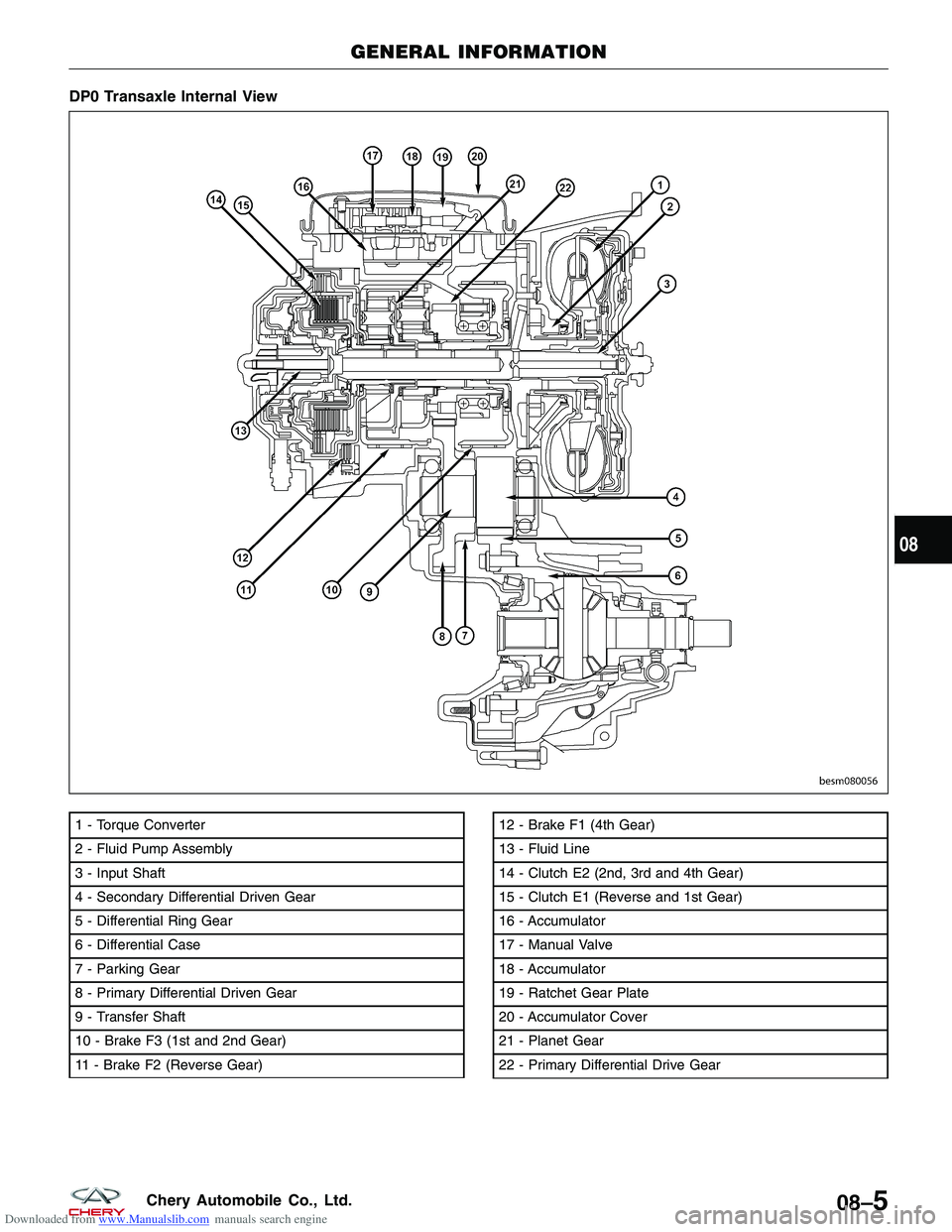
Downloaded from www.Manualslib.com manuals search engine DP0 Transaxle Internal View
1 - Torque Converter
2 - Fluid Pump Assembly
3 - Input Shaft
4 - Secondary Differential Driven Gear
5 - Differential Ring Gear
6 - Differential Case
7 - Parking Gear
8 - Primary Differential Driven Gear
9 - Transfer Shaft
10 - Brake F3 (1st and 2nd Gear)
11 - Brake F2 (Reverse Gear)12 - Brake F1 (4th Gear)
13 - Fluid Line
14 - Clutch E2 (2nd, 3rd and 4th Gear)
15 - Clutch E1 (Reverse and 1st Gear)
16 - Accumulator
17 - Manual Valve
18 - Accumulator
19 - Ratchet Gear Plate
20 - Accumulator Cover
21 - Planet Gear
22 - Primary Differential Drive Gear
GENERAL INFORMATION
BESM080056
08
08–5Chery Automobile Co., Ltd.
Page 951 of 1903
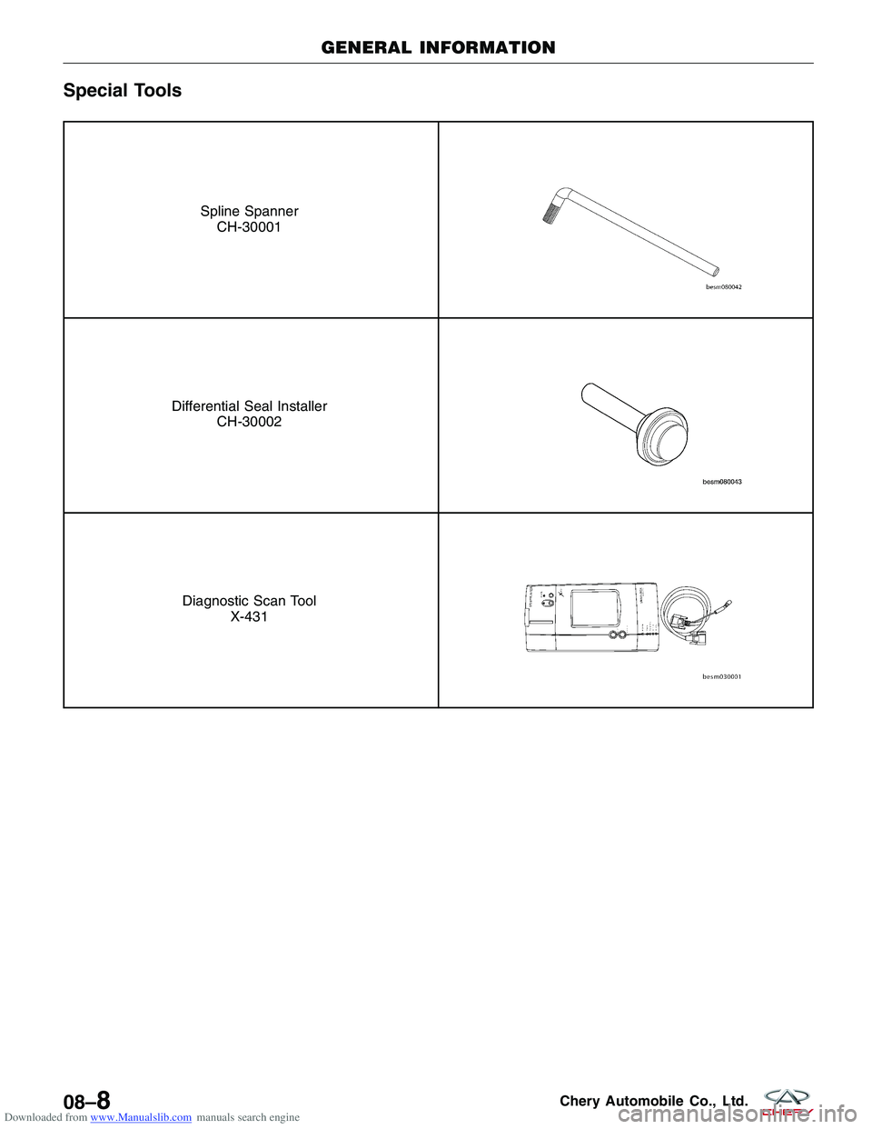
Downloaded from www.Manualslib.com manuals search engine Special Tools
Spline SpannerCH-30001
Differential Seal Installer CH-30002
Diagnostic Scan Tool X-431
GENERAL INFORMATION
08–8Chery Automobile Co., Ltd.
Page 1190 of 1903
Downloaded from www.Manualslib.com manuals search engine GENERAL INFORMATION
Description
The QR523 five-speed transaxle is a constant-mesh manual transaxle that is synchronized in all gear ranges, includ-
ing reverse.
The transaxle consists of three major sub-assemblies:
•Input shaft
• Output shaft
• Differential transaxle assembly
The transaxle shift system consists of the following components:
• Mechanical shift cover
• Shift rails
• Shift forks
08
08–247Chery Automobile Co., Ltd.
Page 1192 of 1903
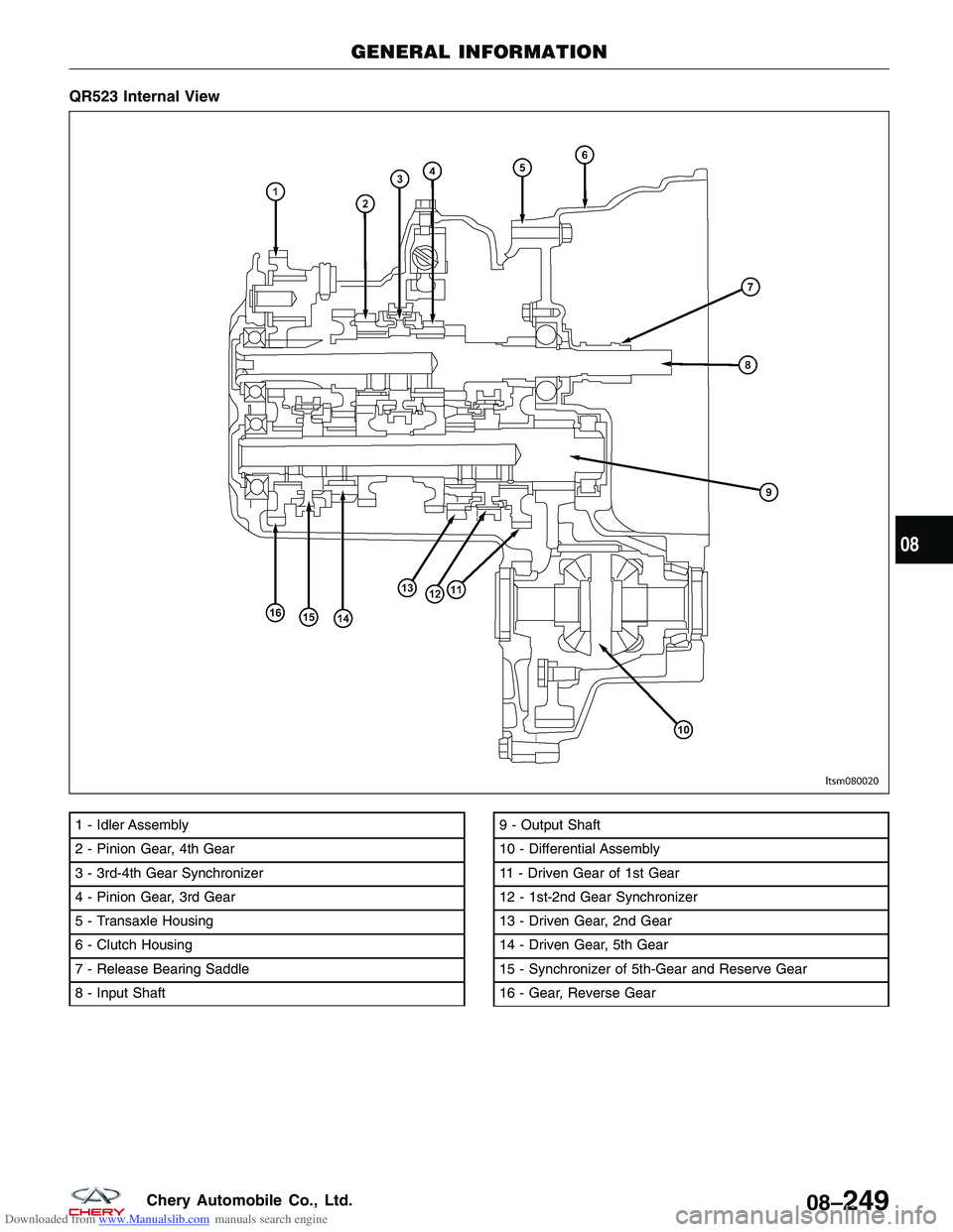
Downloaded from www.Manualslib.com manuals search engine QR523 Internal View
1 - Idler Assembly
2 - Pinion Gear, 4th Gear
3 - 3rd-4th Gear Synchronizer
4 - Pinion Gear, 3rd Gear
5 - Transaxle Housing
6 - Clutch Housing
7 - Release Bearing Saddle
8 - Input Shaft9 - Output Shaft
10 - Differential Assembly
11 - Driven Gear of 1st Gear
12 - 1st-2nd Gear Synchronizer
13 - Driven Gear, 2nd Gear
14 - Driven Gear, 5th Gear
15 - Synchronizer of 5th-Gear and Reserve Gear
16 - Gear, Reverse Gear
GENERAL INFORMATION
LTSM080020
08
08–249Chery Automobile Co., Ltd.
Page 1193 of 1903
Downloaded from www.Manualslib.com manuals search engine Operation
The following are the details of the manual transaxle:
Neutral
Engine power is transmitted to the input shaft via the clutch assembly and the input shaft turns. Since no synchro-
nizers are engaged on either the input or output shafts, power is not transmitted to the output shafts, power is not
transmitted to the output shaft and the differential does not turn.
1st Gear
Engine power is transmitted to the input shaft via the clutch assembly and the input shaft turns. The input shaft first
gear is integral to the input shaft, and is in constant mesh with the intermediate shaft first speed gear. Because of
this constant mesh, the output shaft first speed gear freewheels until first gear is selected. As the gearshift lever is
moved to the first gear position, the 1-2 fork moves the 1-2 synchronizer sleeve towards first gear on the output
shaft. The synchronizer sleeve engages the first gear clutch teeth, engaging the gear to the output shaft, and allow-
ing power to transmit through the output shaft to the differential.
2nd Gear
Engine power is transmitted to the input shaft via the clutch assembly and the input shaft turns. The input shaft
second gear is integral to the input shaft, and is in constant mesh with the output shaft second speed gear. Because
of this constant mesh, the output shaft second speed gear freewheels until second gear is selected. As the gearshift
lever is moved to the second gear position, the 1-2 fork moves the 1-2 synchronizer sleeve towards second gear on
the output shaft. The synchronizer sleeve engages the second gear clutch teeth, engaging the gear to the output
shaft, and allowing power to transmit through the output shaft to the differential.
3rd Gear
Engine power is transmitted to the input shaft via the clutch assembly and the input shaft turns. The input shaft third
speed gear is in constant mesh with the output shaft 3-4 cluster gear which is fixed to the output shaft. Because of
this constant mesh, the input shaft third speed gear freewheels until third gear is selected. As the gearshift lever is
moved to the third gear position, the 3-4 fork moves the 3-4 synchronizer sleeve towards third gear on the input
shaft. The synchronizer sleeve engages the third gear clutch teeth, engaging the gear to the input shaft, and allowing
power to transmit through the output shaft to the differential.
4th Gear
Engine power is transmitted to the input shaft via the clutch assembly and the input shaft turns. The input shaft fourth
speed gear is in constant mesh with the output shaft 3-4 cluster gear which is fixed to the output shaft. Because of
this constant mesh, the input shaft fourth speed gear freewheels until fourth gear is selected. As the gearshift lever
is moved to the fourth gear position, the 3-4 fork moves the 3-4 synchronizer sleeve towards fourth gear on the input
shaft. The synchronizer sleeve engages the fourth gear clutch teeth, engaging the gear to the input shaft, and allow-
ing power to transmit through the output shaft to the differential.
5th Gear
Engine power is transmitted to the input shaft via the clutch assembly and the input shaft turns. The input shaft fifth
speed gear is pressed on to the input shaft, and is in constant mesh with the output shaft fifth speed gear. Because
of this constant mesh, the output shaft fifth speed gear freewheels until fifth gear is selected. As the gearshift lever
is moved to the fifth gear position, the 5-R fork moves the 5-R synchronizer sleeve towards the output shaft fifth
speed gear. The synchronizer sleeve engages the fifth gear clutch teeth, engaging the gear to the input shaft, and
allowing power to transmit through the output shaft to the differential.
Reverse Gear
Engine power is transmitted to the input shaft via the clutch assembly and the input shaft turns. The input shaft
reverse gear is integral to the input shaft, and is in constant mesh with the reverse idler gear. The reverse idler gear,
which reverses the rotation of the output shaft, is in constant mesh with the output shaft reverse gear. Because of
this constant mesh, the output shaft reverse gear freewheels until reverse gear is selected. As the gearshift lever is
moved to the reverse gear position, the 5-R fork moves the 5-R synchronizer sleeve towards the output shaft reverse
gear. The synchronizer sleeve engages the reverse gear clutch teeth, engaging the gear to the output shaft, and
allowing power to transmit through the output shaft to the differential.
GENERAL INFORMATION
08–250Chery Automobile Co., Ltd.
Page 1194 of 1903
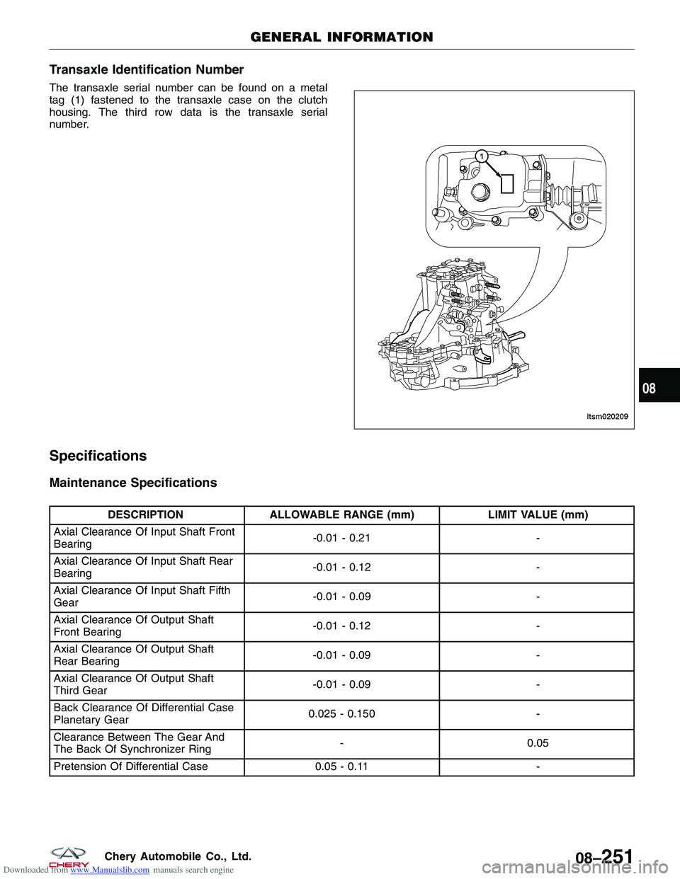
Downloaded from www.Manualslib.com manuals search engine Transaxle Identification Number
The transaxle serial number can be found on a metal
tag (1) fastened to the transaxle case on the clutch
housing. The third row data is the transaxle serial
number.
Specifications
Maintenance Specifications
DESCRIPTIONALLOWABLE RANGE (mm) LIMIT VALUE (mm)
Axial Clearance Of Input Shaft Front
Bearing -0.01 - 0.21
-
Axial Clearance Of Input Shaft Rear
Bearing -0.01 - 0.12
-
Axial Clearance Of Input Shaft Fifth
Gear -0.01 - 0.09
-
Axial Clearance Of Output Shaft
Front Bearing -0.01 - 0.12
-
Axial Clearance Of Output Shaft
Rear Bearing -0.01 - 0.09
-
Axial Clearance Of Output Shaft
Third Gear -0.01 - 0.09
-
Back Clearance Of Differential Case
Planetary Gear 0.025 - 0.150
-
Clearance Between The Gear And
The Back Of Synchronizer Ring -
0.05
Pretension Of Differential Case 0.05 - 0.11-
GENERAL INFORMATION
LTSM020209
08
08–251Chery Automobile Co., Ltd.
Page 1196 of 1903
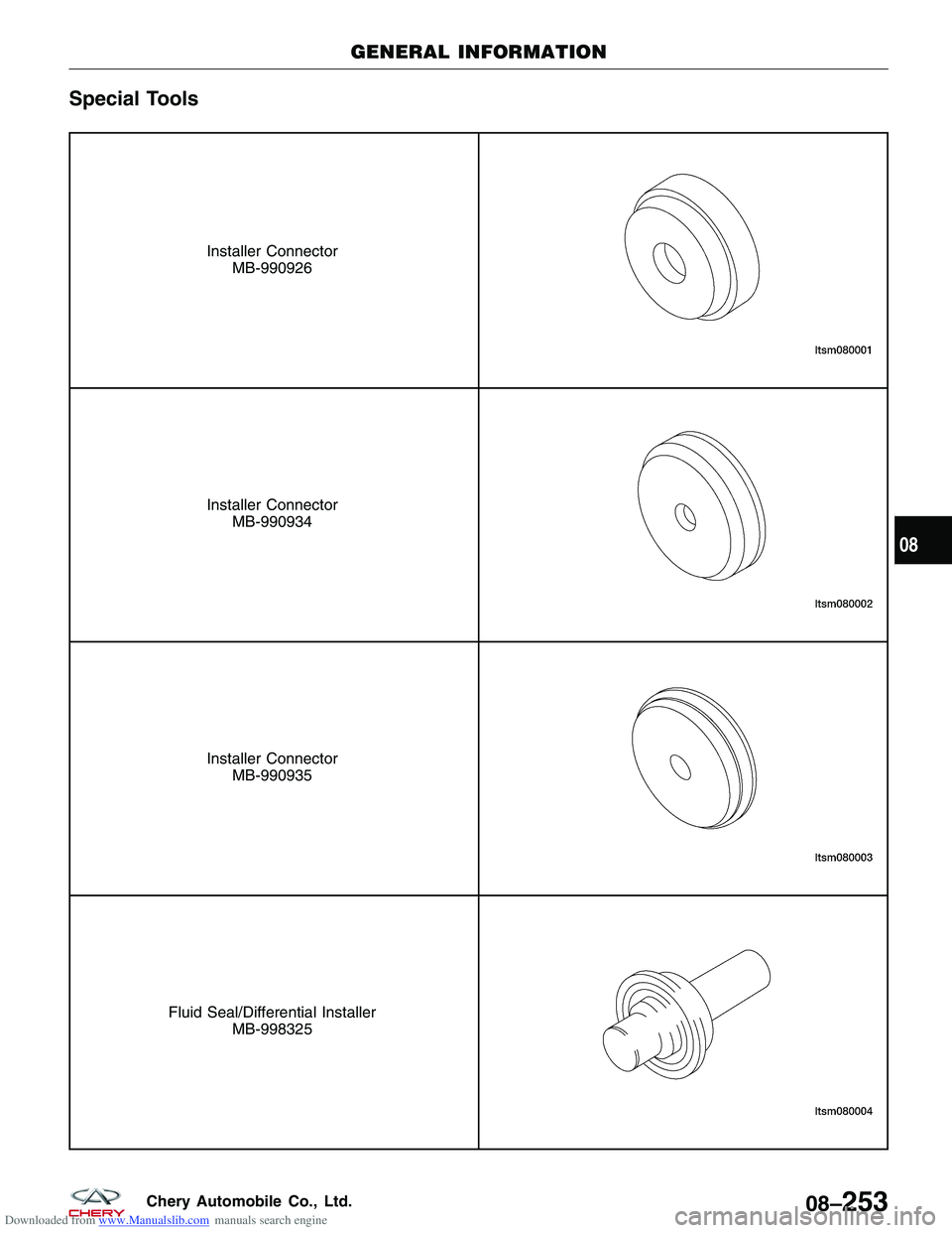
Downloaded from www.Manualslib.com manuals search engine Special Tools
Installer ConnectorMB-990926
Installer ConnectorMB-990934
Installer ConnectorMB-990935
Fluid Seal/Differential Installer MB-998325
GENERAL INFORMATION
08
08–253Chery Automobile Co., Ltd.
Page 1216 of 1903
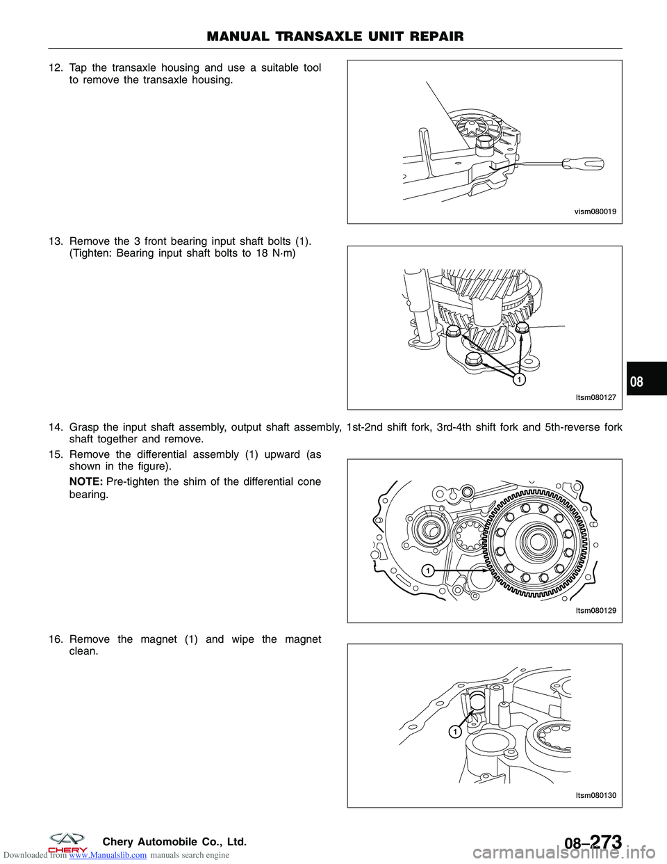
Downloaded from www.Manualslib.com manuals search engine 12. Tap the transaxle housing and use a suitable toolto remove the transaxle housing.
13. Remove the 3 front bearing input shaft bolts (1). (Tighten: Bearing input shaft bolts to 18 N·m)
14. Grasp the input shaft assembly, output shaft assembly, 1st-2nd shift fork, 3rd-4th shift fork and 5th-reverse fork shaft together and remove.
15. Remove the differential assembly (1) upward (as shown in the figure).
NOTE: Pre-tighten the shim of the differential cone
bearing.
16. Remove the magnet (1) and wipe the magnet clean.
MANUAL TRANSAXLE UNIT REPAIR
VISM080019
LTSM080127
LTSM080129
LTSM080130
08
08–273Chery Automobile Co., Ltd.