power steering CHERY TIGGO 2009 Service Repair Manual
[x] Cancel search | Manufacturer: CHERY, Model Year: 2009, Model line: TIGGO, Model: CHERY TIGGO 2009Pages: 1903, PDF Size: 33.38 MB
Page 26 of 1903
Downloaded from www.Manualslib.com manuals search engine HOW TO LOCATE ELECTRICAL SCHEMATICS IN THESERVICE MANUAL
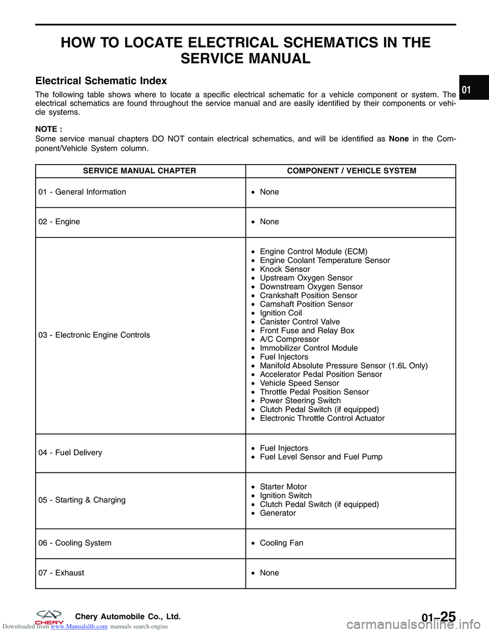
Electrical Schematic Index
The following table shows where to locate a specific electrical schematic for a vehicle component or system. The
electrical schematics are found throughout the service manual and are easily identified by their components or vehi-
cle systems.
NOTE :
Some service manual chapters DO NOT contain electrical schematics, and will be identified as Nonein the Com-
ponent/Vehicle System column.
SERVICE MANUAL CHAPTER COMPONENT / VEHICLE SYSTEM
01 - General Information •None
02 - Engine •None
03 - Electronic Engine Controls •
Engine Control Module (ECM)
• Engine Coolant Temperature Sensor
• Knock Sensor
• Upstream Oxygen Sensor
• Downstream Oxygen Sensor
• Crankshaft Position Sensor
• Camshaft Position Sensor
• Ignition Coil
• Canister Control Valve
• Front Fuse and Relay Box
• A/C Compressor
• Immobilizer Control Module
• Fuel Injectors
• Manifold Absolute Pressure Sensor (1.6L Only)
• Accelerator Pedal Position Sensor
• Vehicle Speed Sensor
• Throttle Pedal Position Sensor
• Power Steering Switch
• Clutch Pedal Switch (if equipped)
• Electronic Throttle Control Actuator
04 - Fuel Delivery •
Fuel Injectors
• Fuel Level Sensor and Fuel Pump
05 - Starting & Charging •
Starter Motor
• Ignition Switch
• Clutch Pedal Switch (if equipped)
• Generator
06 - Cooling System •Cooling Fan
07 - Exhaust •None
01
01–25Chery Automobile Co., Ltd.
Page 27 of 1903
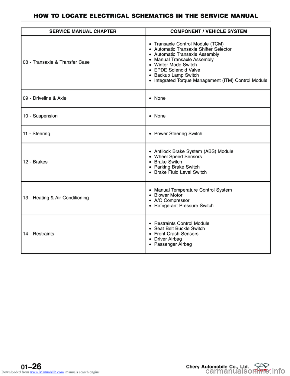
Downloaded from www.Manualslib.com manuals search engine SERVICE MANUAL CHAPTERCOMPONENT / VEHICLE SYSTEM
08 - Transaxle & Transfer Case •
Transaxle Control Module (TCM)
• Automatic Transaxle Shifter Selector
• Automatic Transaxle Assembly
• Manual Transaxle Assembly
• Winter Mode Switch
• EPDE Solenoid Valve
• Backup Lamp Switch
• Integrated Torque Management (ITM) Control Module
09 - Driveline & Axle •None
10 - Suspension •None
11 - Steering •Power Steering Switch
12 - Brakes •
Antilock Brake System (ABS) Module
• Wheel Speed Sensors
• Brake Switch
• Parking Brake Switch
• Brake Fluid Level Switch
13 - Heating & Air Conditioning •
Manual Temperature Control System
• Blower Motor
• A/C Compressor
• Refrigerant Pressure Switch
14 - Restraints •
Restraints Control Module
• Seat Belt Buckle Switch
• Front Crash Sensors
• Driver Airbag
• Passenger Airbag
HOW TO LOCATE ELECTRICAL SCHEMATICS IN THE SERVICE MANUAL
01–26Chery Automobile Co., Ltd.
Page 46 of 1903
Downloaded from www.Manualslib.com manuals search engine ON-VEHICLE SERVICE
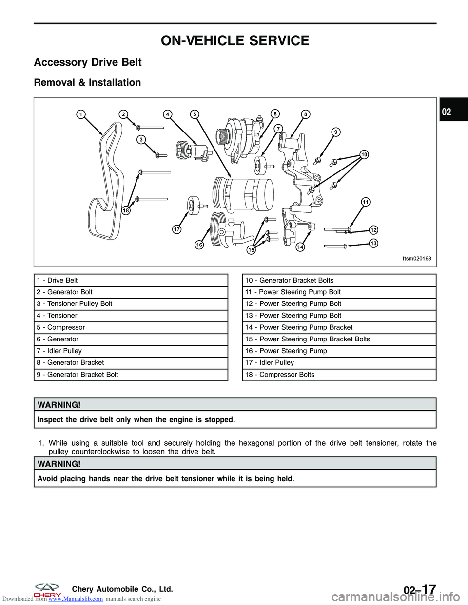
Accessory Drive Belt
Removal & Installation
WARNING!
Inspect the drive belt only when the engine is stopped.
1. While using a suitable tool and securely holding the hexagonal portion of the drive belt tensioner, rotate thepulley counterclockwise to loosen the drive belt.
WARNING!
Avoid placing hands near the drive belt tensioner while it is being held.
1 - Drive Belt
2 - Generator Bolt
3 - Tensioner Pulley Bolt
4 - Tensioner
5 - Compressor
6 - Generator
7 - Idler Pulley
8 - Generator Bracket
9 - Generator Bracket Bolt10 - Generator Bracket Bolts
11 - Power Steering Pump Bolt
12 - Power Steering Pump Bolt
13 - Power Steering Pump Bolt
14 - Power Steering Pump Bracket
15 - Power Steering Pump Bracket Bolts
16 - Power Steering Pump
17 - Idler Pulley
18 - Compressor Bolts
LTSM020163
02
02–17Chery Automobile Co., Ltd.
Page 62 of 1903
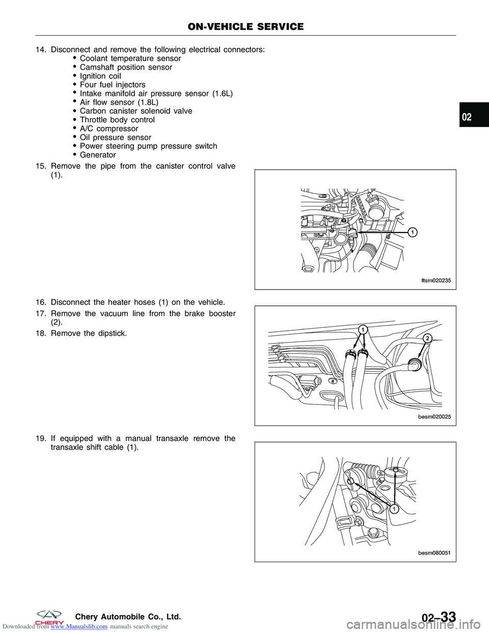
Downloaded from www.Manualslib.com manuals search engine 14.Disconnectandremovethefollowingelectricalconnectors:
€Coolanttemperaturesensor
€Camshaftpositionsensor
€Ignitioncoil
€Fourfuelinjectors
€Intakemanifoldairpressuresensor(1.6L)
€Airflowsensor(1.8L)
€Carboncanistersolenoidvalve
€Throttlebodycontrol
€A/Ccompressor
€Oilpressuresensor
€Powersteeringpumppressureswitch
€Generator
15.Removethepipefromthecanistercontrolvalve
(1).
16.Disconnecttheheaterhoses(1)onthevehicle.
17.Removethevacuumlinefromthebrakebooster
(2).
18.Removethedipstick.
19.Ifequippedwithamanualtransaxleremovethe
transaxleshiftcable(1).
ON-VEHICLESERVICE
LTSM020235
BESM020025
BESM080051
02
02–33CheryAutomobileCo.,Ltd.
Page 63 of 1903
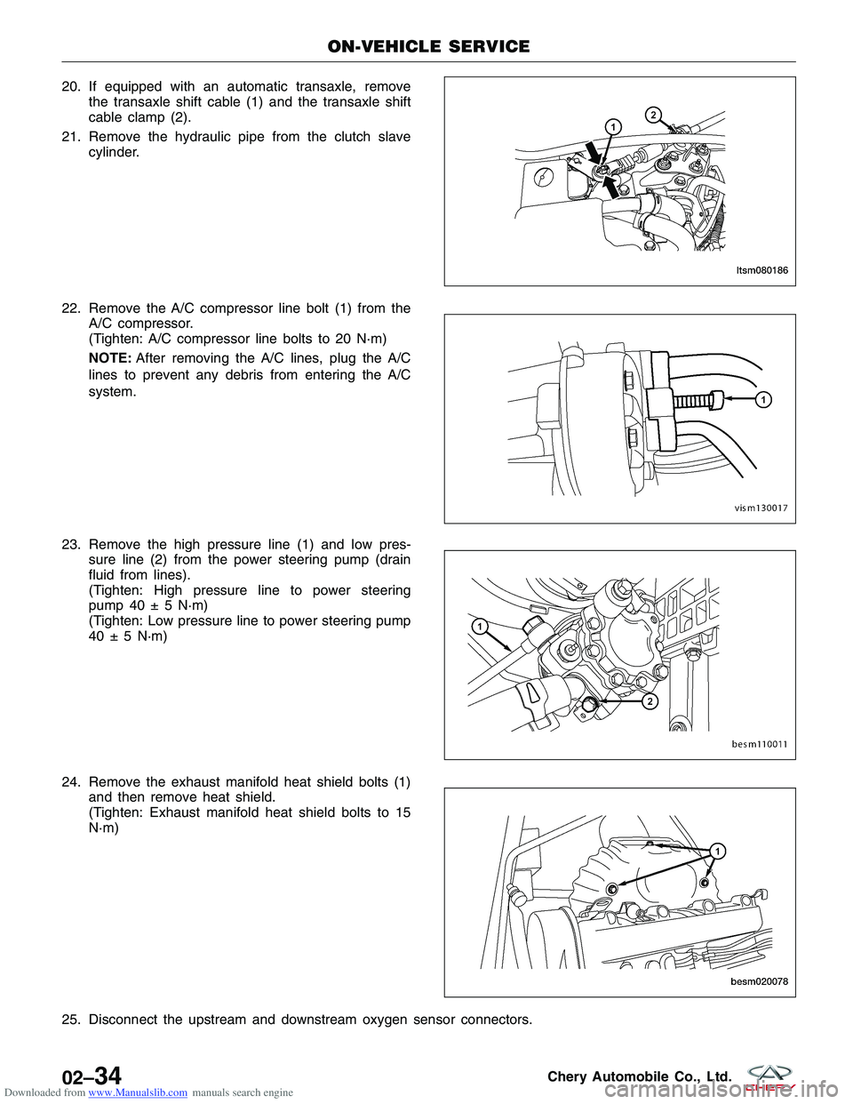
Downloaded from www.Manualslib.com manuals search engine 20. If equipped with an automatic transaxle, removethe transaxle shift cable (1) and the transaxle shift
cable clamp (2).
21. Remove the hydraulic pipe from the clutch slave cylinder.
22. Remove the A/C compressor line bolt (1) from the A/C compressor.
(Tighten: A/C compressor line bolts to 20 N·m)
NOTE: After removing the A/C lines, plug the A/C
lines to prevent any debris from entering the A/C
system.
23. Remove the high pressure line (1) and low pres- sure line (2) from the power steering pump (drain
fluid from lines).
(Tighten: High pressure line to power steering
pump 40 ± 5 N·m)
(Tighten: Low pressure line to power steering pump
40 ± 5 N·m)
24. Remove the exhaust manifold heat shield bolts (1) and then remove heat shield.
(Tighten: Exhaust manifold heat shield bolts to 15
N·m)
25. Disconnect the upstream and downstream oxygen sensor connectors.
ON-VEHICLE SERVICE
LTSM080186
VISM130017
BESM110011
BESM020078
02–34Chery Automobile Co., Ltd.
Page 66 of 1903
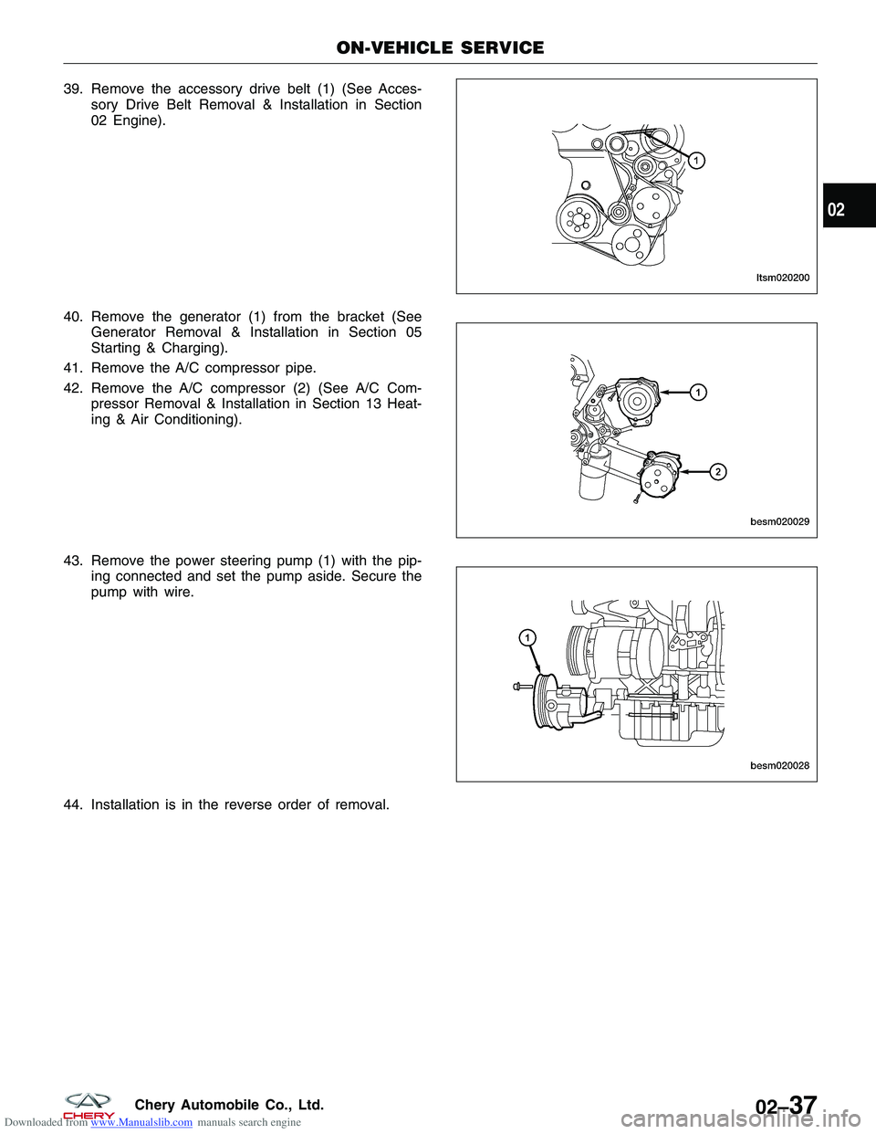
Downloaded from www.Manualslib.com manuals search engine 39. Remove the accessory drive belt (1) (See Acces-sory Drive Belt Removal & Installation in Section
02 Engine).
40. Remove the generator (1) from the bracket (See Generator Removal & Installation in Section 05
Starting & Charging).
41. Remove the A/C compressor pipe.
42. Remove the A/C compressor (2) (See A/C Com- pressor Removal & Installation in Section 13 Heat-
ing & Air Conditioning).
43. Remove the power steering pump (1) with the pip- ing connected and set the pump aside. Secure the
pump with wire.
44. Installation is in the reverse order of removal.
ON-VEHICLE SERVICE
LTSM020200
BESM020029
BESM020028
02
02–37Chery Automobile Co., Ltd.
Page 120 of 1903
Downloaded from www.Manualslib.com manuals search engine ON-VEHICLE SERVICE
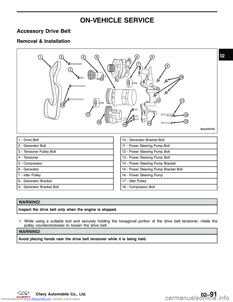
Accessory Drive Belt
Removal & Installation
WARNING!
Inspect the drive belt only when the engine is stopped.
1. While using a suitable tool and securely holding the hexagonal portion of the drive belt tensioner, rotate thepulley counterclockwise to loosen the drive belt.
WARNING!
Avoid placing hands near the drive belt tensioner while it is being held.
1 - Drive Belt
2 - Generator Bolt
3 - Tensioner Pulley Bolt
4 - Tensioner
5 - Compressor
6 - Generator
7 - Idler Pulley
8 - Generator Bracket
9 - Generator Bracket Bolt10 - Generator Bracket Bolt
11 - Power Steering Pump Bolt
12 - Power Steering Pump Bolt
13 - Power Steering Pump Bolt
14 - Power Steering Pump Bracket
15 - Power Steering Pump Bracket Bolt
16 - Power Steering Pump
17 - Idler Pulley
18 - Compressor Bolt
LTSM020163
02
02–91Chery Automobile Co., Ltd.
Page 136 of 1903
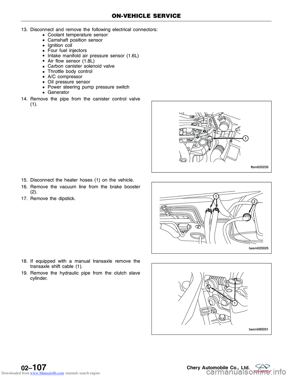
Downloaded from www.Manualslib.com manuals search engine 13.Disconnectandremovethefollowingelectricalconnectors:
€Coolanttemperaturesensor
€Camshaftpositionsensor
€Ignitioncoil
€Fourfuelinjectors
€Intakemanifoldairpressuresensor(1.6L)
€Airflowsensor(1.8L)
€Carboncanistersolenoidvalve
€Throttlebodycontrol
€A/Ccompressor
€Oilpressuresensor
€Powersteeringpumppressureswitch
€Generator
14.Removethepipefromthecanistercontrolvalve
(1).
15.Disconnecttheheaterhoses(1)onthevehicle.
16.Removethevacuumlinefromthebrakebooster
(2).
17.Removethedipstick.
18.Ifequippedwithamanualtransaxleremovethe
transaxleshiftcable(1).
19.Removethehydraulicpipefromtheclutchslave
cylinder.
ON-VEHICLESERVICE
LTSM020235
BESM020025
BESM080051
02–107CheryAutomobileCo.,Ltd.
Page 137 of 1903
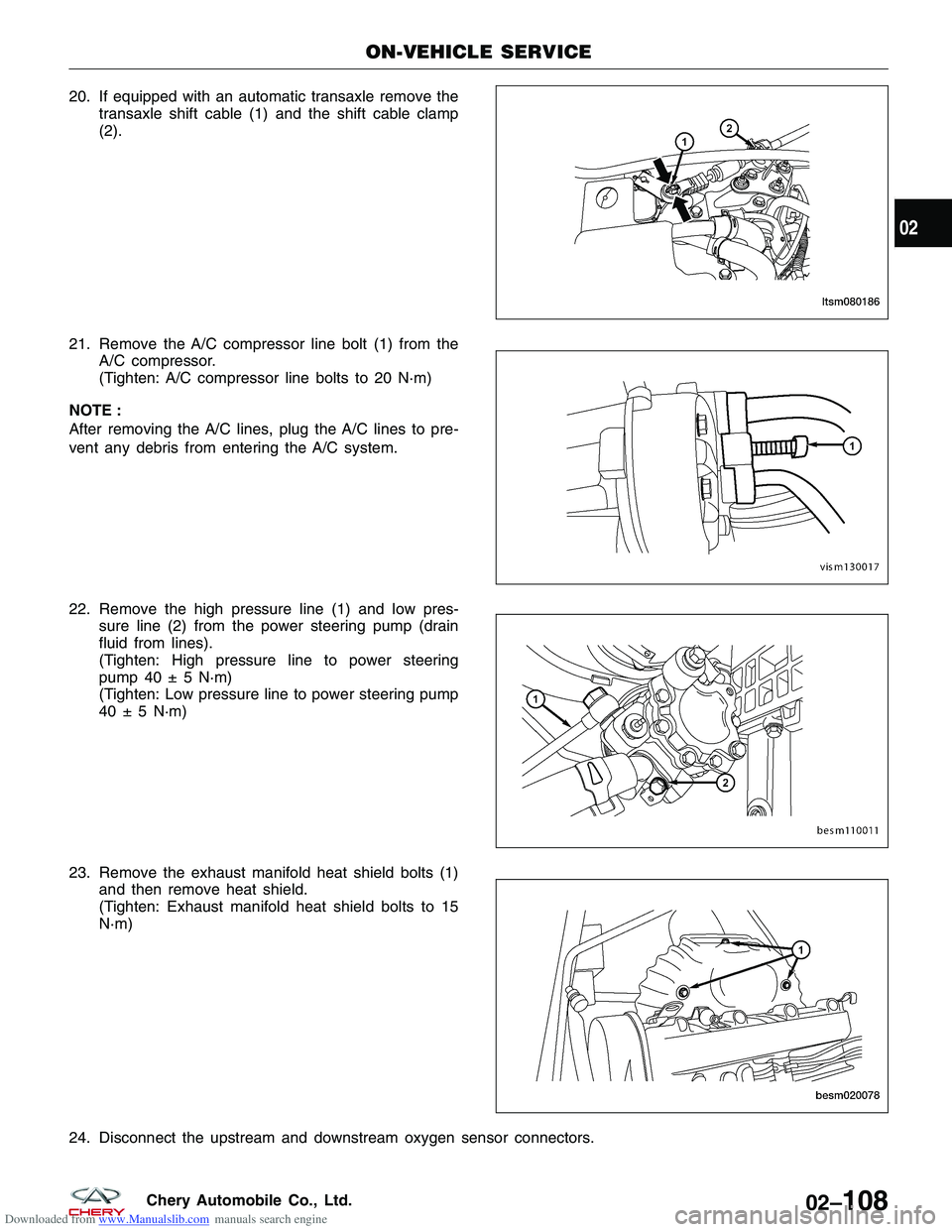
Downloaded from www.Manualslib.com manuals search engine 20. If equipped with an automatic transaxle remove thetransaxle shift cable (1) and the shift cable clamp
(2).
21. Remove the A/C compressor line bolt (1) from the A/C compressor.
(Tighten: A/C compressor line bolts to 20 N·m)
NOTE :
After removing the A/C lines, plug the A/C lines to pre-
vent any debris from entering the A/C system.
22. Remove the high pressure line (1) and low pres- sure line (2) from the power steering pump (drain
fluid from lines).
(Tighten: High pressure line to power steering
pump 40 ± 5 N·m)
(Tighten: Low pressure line to power steering pump
40 ± 5 N·m)
23. Remove the exhaust manifold heat shield bolts (1) and then remove heat shield.
(Tighten: Exhaust manifold heat shield bolts to 15
N·m)
24. Disconnect the upstream and downstream oxygen sensor connectors.
ON-VEHICLE SERVICE
LTSM080186
VISM130017
BESM110011
BESM020078
02
02–108Chery Automobile Co., Ltd.
Page 140 of 1903
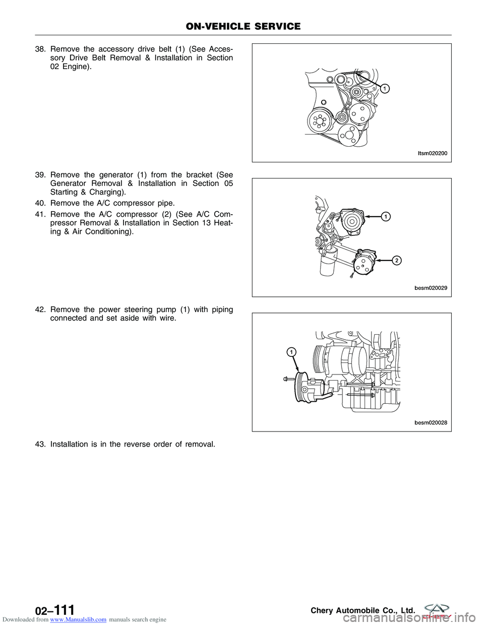
Downloaded from www.Manualslib.com manuals search engine 38. Remove the accessory drive belt (1) (See Acces-sory Drive Belt Removal & Installation in Section
02 Engine).
39. Remove the generator (1) from the bracket (See Generator Removal & Installation in Section 05
Starting & Charging).
40. Remove the A/C compressor pipe.
41. Remove the A/C compressor (2) (See A/C Com- pressor Removal & Installation in Section 13 Heat-
ing & Air Conditioning).
42. Remove the power steering pump (1) with piping connected and set aside with wire.
43. Installation is in the reverse order of removal.
ON-VEHICLE SERVICE
LTSM020200
BESM020029
BESM020028
02–111Chery Automobile Co., Ltd.