headlamp CHEVROLET AVALANCHE 2012 2.G Owner's Manual
[x] Cancel search | Manufacturer: CHEVROLET, Model Year: 2012, Model line: AVALANCHE, Model: CHEVROLET AVALANCHE 2012 2.GPages: 508, PDF Size: 7.78 MB
Page 319 of 508
Black plate (59,1)Chevrolet Avalanche Owner Manual - 2012
Driving and Operating 9-59
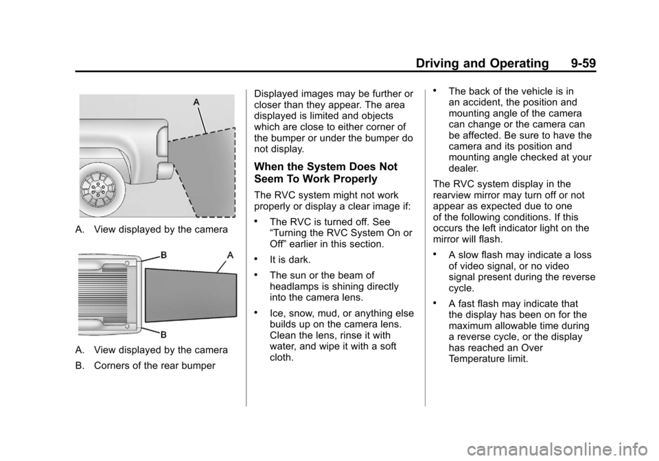
A. View displayed by the camera
A. View displayed by the camera
B. Corners of the rear bumperDisplayed images may be further or
closer than they appear. The area
displayed is limited and objects
which are close to either corner of
the bumper or under the bumper do
not display.
When the System Does Not
Seem To Work Properly
The RVC system might not work
properly or display a clear image if:
.The RVC is turned off. See
“Turning the RVC System On or
Off”
earlier in this section.
.It is dark.
.The sun or the beam of
headlamps is shining directly
into the camera lens.
.Ice, snow, mud, or anything else
builds up on the camera lens.
Clean the lens, rinse it with
water, and wipe it with a soft
cloth.
.The back of the vehicle is in
an accident, the position and
mounting angle of the camera
can change or the camera can
be affected. Be sure to have the
camera and its position and
mounting angle checked at your
dealer.
The RVC system display in the
rearview mirror may turn off or not
appear as expected due to one
of the following conditions. If this
occurs the left indicator light on the
mirror will flash.
.A slow flash may indicate a loss
of video signal, or no video
signal present during the reverse
cycle.
.A fast flash may indicate that
the display has been on for the
maximum allowable time during
a reverse cycle, or the display
has reached an Over
Temperature limit.
Page 336 of 508
Black plate (76,1)Chevrolet Avalanche Owner Manual - 2012
9-76 Driving and Operating
Safety Chains
Always attach chains between the
vehicle and the trailer. Cross the
safety chains under the tongue of
the trailer to help prevent the tongue
from contacting the road if it
becomes separated from the hitch.
Instructions about safety chains
may be provided by the hitch
manufacturer or by the trailer
manufacturer. If the trailer being
towed weighs up to 2 271 kg
(5,000 lbs) with a factory-installed
step bumper, safety chains may be
attached to the attaching points on
the bumper, otherwise, safety
chains should be attached to holes
on the trailer hitch platform. Always
leave just enough slack so the
combination can turn. Never allow
safety chains to drag on the ground.
Trailer Brakes
A loaded trailer that weighs more
than 900 kg (2,000 lbs) needs to
have its own brake system that is
adequate for the weight of the
trailer. Be sure to read and followthe instructions for the trailer brakes
so they are installed, adjusted and
maintained properly.
Do not tap into the vehicle's
hydraulic system.
Trailer Wiring Harness
Heavy-Duty Trailer Wiring Harness
Package
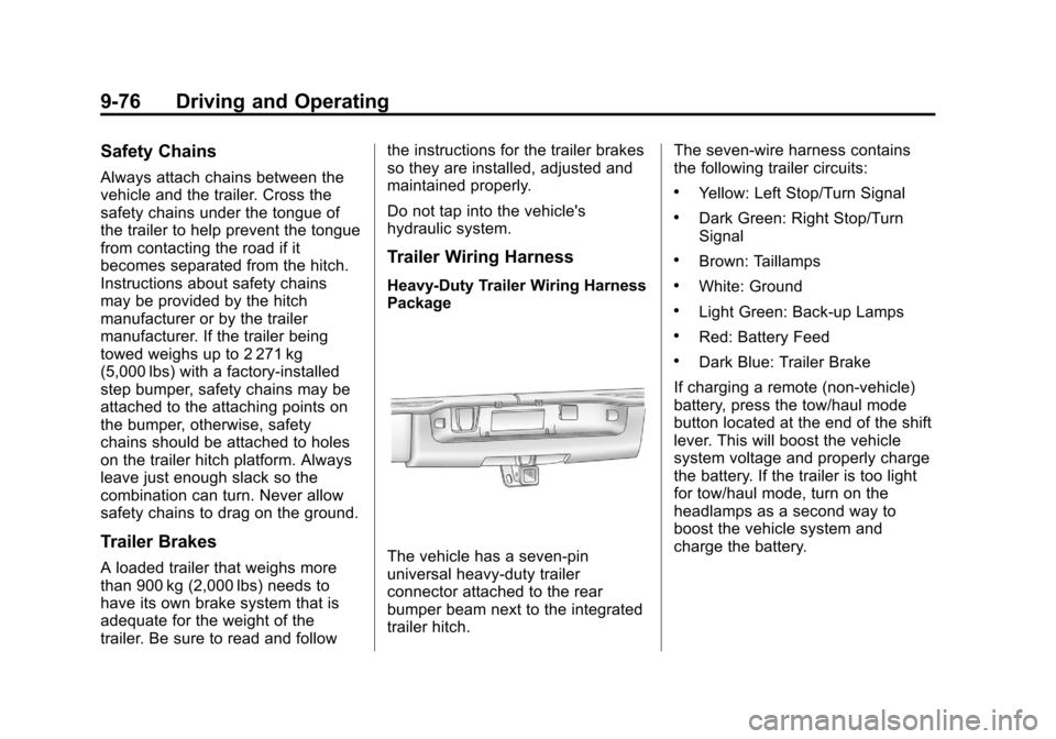
The vehicle has a seven-pin
universal heavy-duty trailer
connector attached to the rear
bumper beam next to the integrated
trailer hitch.
The seven-wire harness contains
the following trailer circuits:
.Yellow: Left Stop/Turn Signal
.Dark Green: Right Stop/Turn
Signal
.Brown: Taillamps
.White: Ground
.Light Green: Back-up Lamps
.Red: Battery Feed
.Dark Blue: Trailer Brake
If charging a remote (non-vehicle)
battery, press the tow/haul mode
button located at the end of the shift
lever. This will boost the vehicle
system voltage and properly charge
the battery. If the trailer is too light
for tow/haul mode, turn on the
headlamps as a second way to
boost the vehicle system and
charge the battery.
Page 345 of 508
Black plate (1,1)Chevrolet Avalanche Owner Manual - 2012
Vehicle Care 10-1
Vehicle Care
General Information
General Information . . . . . . . . . . 10-2
California Proposition65 Warning . . . . . . . . . . . . . . . . . 10-2
California Perchlorate Materials Requirements . . . . 10-3
Accessories and Modifications . . . . . . . . . . . . . . . 10-3
Vehicle Checks
Doing Your OwnService Work . . . . . . . . . . . . . . . 10-4
Hood . . . . . . . . . . . . . . . . . . . . . . . . 10-5
Engine Compartment Overview . . . . . . . . . . . . . . . . . . . 10-6
Engine Oil . . . . . . . . . . . . . . . . . . . 10-8
Engine Oil Life System . . . . . 10-11
Automatic Transmission Fluid . . . . . . . . . . . . . . . . . . . . . . 10-13
Engine Air Cleaner/Filter . . . . 10-16
Cooling System . . . . . . . . . . . . 10-18
Engine Coolant . . . . . . . . . . . . . 10-18
Engine Overheating . . . . . . . . 10-22
Overheated Engine Protection
Operating Mode . . . . . . . . . . . 10-24 Engine Fan . . . . . . . . . . . . . . . . . 10-25
Power Steering Fluid . . . . . . . 10-25
Washer Fluid . . . . . . . . . . . . . . . 10-26
Brakes . . . . . . . . . . . . . . . . . . . . . 10-27
Brake Fluid . . . . . . . . . . . . . . . . . 10-28
Battery . . . . . . . . . . . . . . . . . . . . . 10-30
Four-Wheel Drive . . . . . . . . . . . 10-30
Front Axle . . . . . . . . . . . . . . . . . . 10-31
Rear Axle . . . . . . . . . . . . . . . . . . 10-31
Starter Switch Check . . . . . . . 10-33
Automatic Transmission Shift
Lock Control Function
Check . . . . . . . . . . . . . . . . . . . . . 10-33
Ignition Transmission Lock Check . . . . . . . . . . . . . . . . . . . . . 10-34
Park Brake and P (Park) Mechanism Check . . . . . . . . 10-34
Wiper Blade Replacement . . . . . . . . . . . . . . 10-35
Glass Replacement . . . . . . . . 10-35
Headlamp Aiming
Headlamp Aiming . . . . . . . . . . 10-35
Bulb Replacement
Bulb Replacement . . . . . . . . . . 10-38
Halogen Bulbs . . . . . . . . . . . . . . 10-38 Taillamps, Turn Signal,
Sidemarker, Stoplamps,
and Back-Up Lamps . . . . . . 10-38
License Plate Lamp . . . . . . . . 10-39
Replacement Bulbs . . . . . . . . . 10-39
Electrical System
Electrical System Overload . . . . . . . . . . . . . . . . . . 10-40
Fuses and Circuit Breakers . . . . . . . . . . . . . . . . . . 10-41
Engine Compartment Fuse Block . . . . . . . . . . . . . . . . . . . . . 10-41
Instrument Panel Fuse Block . . . . . . . . . . . . . . . . . . . . . 10-46
Wheels and Tires
Tires . . . . . . . . . . . . . . . . . . . . . . . . 10-49
Tire Sidewall Labeling . . . . . . 10-50
Tire Designations . . . . . . . . . . . 10-52
Tire Terminology andDefinitions . . . . . . . . . . . . . . . . 10-53
Tire Pressure . . . . . . . . . . . . . . . 10-56
Tire Pressure Monitor System . . . . . . . . . . . . . . . . . . . 10-58
Tire Pressure Monitor Operation . . . . . . . . . . . . . . . . . 10-59
Tire Inspection . . . . . . . . . . . . . . 10-62
Tire Rotation . . . . . . . . . . . . . . . 10-62
Page 379 of 508
Black plate (35,1)Chevrolet Avalanche Owner Manual - 2012
Vehicle Care 10-35
Wiper Blade Replacement
Windshield wiper blades should be
inspected for wear or cracking. See
Maintenance Schedule on
page 11‑3.
Replacement blades come in
different types and are removed in
different ways.
To replace the wiper blade
assembly:
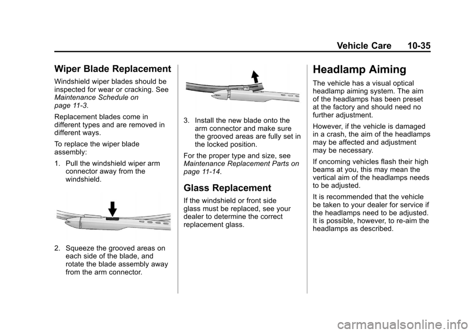
1. Pull the windshield wiper armconnector away from the
windshield.
2. Squeeze the grooved areas on
each side of the blade, and
rotate the blade assembly away
from the arm connector.
3. Install the new blade onto thearm connector and make sure
the grooved areas are fully set in
the locked position.
For the proper type and size, see
Maintenance Replacement Parts on
page 11‑14.
Glass Replacement
If the windshield or front side
glass must be replaced, see your
dealer to determine the correct
replacement glass.
Headlamp Aiming
The vehicle has a visual optical
headlamp aiming system. The aim
of the headlamps has been preset
at the factory and should need no
further adjustment.
However, if the vehicle is damaged
in a crash, the aim of the headlamps
may be affected and adjustment
may be necessary.
If oncoming vehicles flash their high
beams at you, this may mean the
vertical aim of the headlamps needs
to be adjusted.
It is recommended that the vehicle
be taken to your dealer for service if
the headlamps need to be adjusted.
It is possible, however, to re-aim the
headlamps as described.
Page 380 of 508
Black plate (36,1)Chevrolet Avalanche Owner Manual - 2012
10-36 Vehicle Care
The vehicle should:
.Be placed so the headlamps
are 7.6 m (25 ft) from a
light‐colored wall.
.Have all four tires on a level
surface which is level all the
way to the wall.
.Be placed so it is perpendicular
to the wall.
.Not have any snow, ice, or mud
on it.
.Be fully assembled and all other
work stopped while headlamp
aiming is being performed.
.Be loaded with a full tank of
fuel and one person or 75 kg
(160 lbs) sitting on the
driver seat.
.Have the tires properly inflated.
.Have the spare tire in its proper
location in the vehicle.Headlamp aiming is done with the
vehicle's low-beam headlamps.
The high-beam headlamps will be
correctly aimed if the low-beam
headlamps are aimed properly.
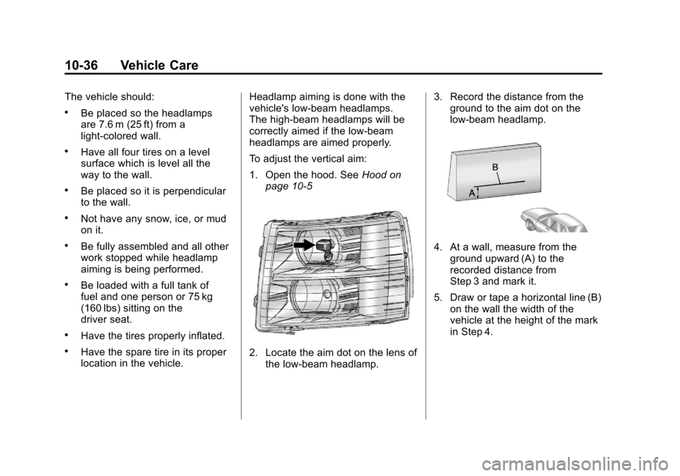
To adjust the vertical aim:
1. Open the hood. See
Hood on
page 10‑52. Locate the aim dot on the lens of the low‐beam headlamp. 3. Record the distance from the
ground to the aim dot on the
low‐beam headlamp.
4. At a wall, measure from the
ground upward (A) to the
recorded distance from
Step 3 and mark it.
5. Draw or tape a horizontal line (B) on the wall the width of the
vehicle at the height of the mark
in Step 4.
Page 381 of 508
Black plate (37,1)Chevrolet Avalanche Owner Manual - 2012
Vehicle Care 10-37
Notice:Do not cover a headlamp
to improve beam cut-off when
aiming. Covering a headlamp may
cause excessive heat build-up
which may cause damage to the
headlamp.
6. Turn on the low-beam
headlamps and place a piece of
cardboard or equivalent in front
of the headlamp not being
adjusted. This allows only the
beam of light from the headlamp
being adjusted to be seen on the
flat surface.
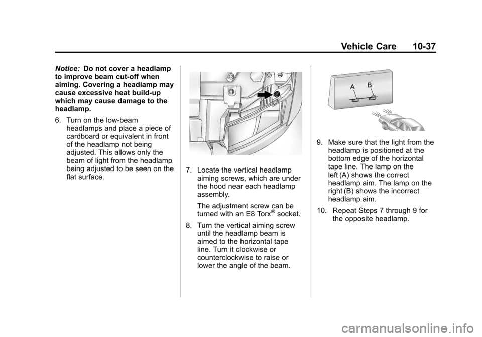
7. Locate the vertical headlampaiming screws, which are under
the hood near each headlamp
assembly.
The adjustment screw can be
turned with an E8 Torx
®socket.
8. Turn the vertical aiming screw until the headlamp beam is
aimed to the horizontal tape
line. Turn it clockwise or
counterclockwise to raise or
lower the angle of the beam.
9. Make sure that the light from theheadlamp is positioned at the
bottom edge of the horizontal
tape line. The lamp on the
left (A) shows the correct
headlamp aim. The lamp on the
right (B) shows the incorrect
headlamp aim.
10. Repeat Steps 7 through 9 for the opposite headlamp.
Page 384 of 508
Black plate (40,1)Chevrolet Avalanche Owner Manual - 2012
10-40 Vehicle Care
Electrical System
Electrical System
Overload
The vehicle has fuses and circuit
breakers to protect against an
electrical system overload.
When the current electrical load is
too heavy, the circuit breaker opens
and closes, protecting the circuit
until the current load returns to
normal or the problem is fixed. This
greatly reduces the chance of circuit
overload and fire caused by
electrical problems.
Fuses and circuit breakers protect
power devices in the vehicle.Replace a bad fuse with a new one
of the identical size and rating.
If there is a problem on the road and
a fuse needs to be replaced, the
same amperage fuse can be
borrowed. Choose some feature of
the vehicle that is not needed to use
and replace it as soon as possible.
Headlamp Wiring
An electrical overload may cause
the lamps to go on and off, or in
some cases to remain off. Have the
headlamp wiring checked right away
if the lamps go on and off or
remain off.
Windshield Wipers
If the wiper motor overheats due to
heavy snow or ice, the windshield
wipers will stop until the motor cools
and will then restart.
Although the circuit is protected
from electrical overload, overload
due to heavy snow or ice may
cause wiper linkage damage.
Always clear ice and heavy snow
from the windshield before using the
windshield wipers.
If the overload is caused by an
electrical problem and not snow or
ice, be sure to get it fixed.
Page 387 of 508
Black plate (43,1)Chevrolet Avalanche Owner Manual - 2012
Vehicle Care 10-43
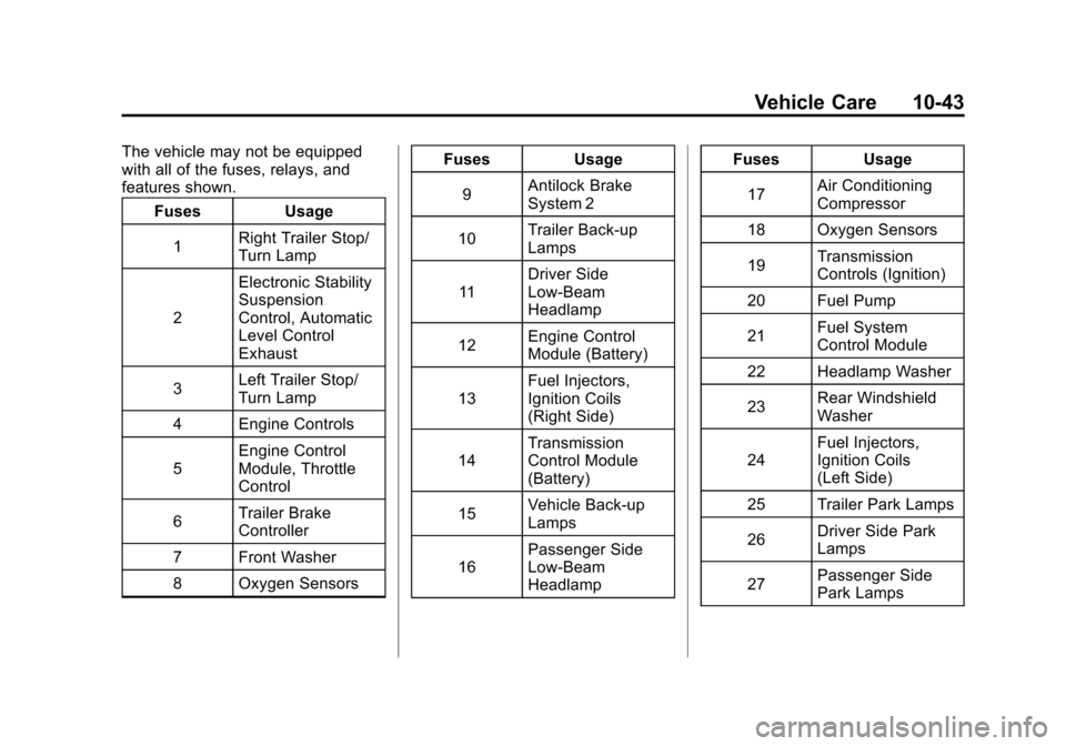
The vehicle may not be equipped
with all of the fuses, relays, and
features shown.Fuses Usage
1 Right Trailer Stop/
Turn Lamp
2 Electronic Stability
Suspension
Control, Automatic
Level Control
Exhaust
3 Left Trailer Stop/
Turn Lamp
4 Engine Controls
5 Engine Control
Module, Throttle
Control
6 Trailer Brake
Controller
7 Front Washer
8 Oxygen Sensors Fuses Usage
9 Antilock Brake
System 2
10 Trailer Back-up
Lamps
11 Driver Side
Low-Beam
Headlamp
12 Engine Control
Module (Battery)
13 Fuel Injectors,
Ignition Coils
(Right Side)
14 Transmission
Control Module
(Battery)
15 Vehicle Back-up
Lamps
16 Passenger Side
Low-Beam
Headlamp Fuses Usage
17 Air Conditioning
Compressor
18 Oxygen Sensors
19 Transmission
Controls (Ignition)
20 Fuel Pump
21 Fuel System
Control Module
22 Headlamp Washer
23 Rear Windshield
Washer
24 Fuel Injectors,
Ignition Coils
(Left Side)
25 Trailer Park Lamps
26 Driver Side Park
Lamps
27 Passenger Side
Park Lamps
Page 388 of 508
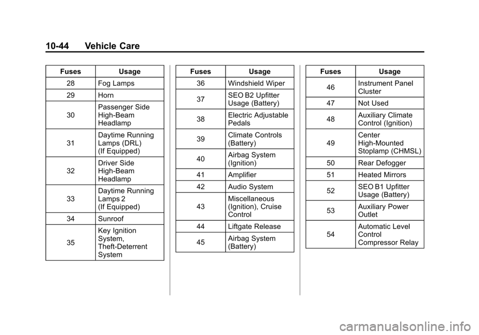
Black plate (44,1)Chevrolet Avalanche Owner Manual - 2012
10-44 Vehicle Care
FusesUsage
28 Fog Lamps
29 Horn
30 Passenger Side
High-Beam
Headlamp
31 Daytime Running
Lamps (DRL)
(If Equipped)
32 Driver Side
High-Beam
Headlamp
33 Daytime Running
Lamps 2
(If Equipped)
34 Sunroof
35 Key Ignition
System,
Theft‐Deterrent
System Fuses
Usage
36 Windshield Wiper
37 SEO B2 Upfitter
Usage (Battery)
38 Electric Adjustable
Pedals
39 Climate Controls
(Battery)
40 Airbag System
(Ignition)
41 Amplifier
42 Audio System
43 Miscellaneous
(Ignition), Cruise
Control
44 Liftgate Release
45 Airbag System
(Battery) Fuses
Usage
46 Instrument Panel
Cluster
47 Not Used
48 Auxiliary Climate
Control (Ignition)
49 Center
High-Mounted
Stoplamp (CHMSL)
50 Rear Defogger
51 Heated Mirrors
52 SEO B1 Upfitter
Usage (Battery)
53 Auxiliary Power
Outlet
54 Automatic Level
Control
Compressor Relay
Page 389 of 508
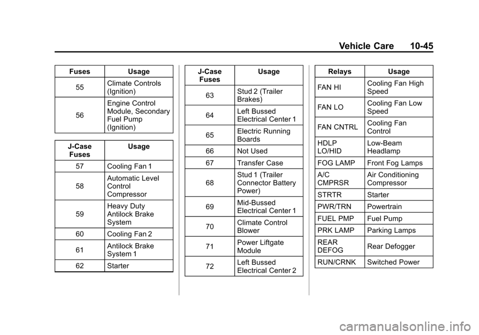
Black plate (45,1)Chevrolet Avalanche Owner Manual - 2012
Vehicle Care 10-45
FusesUsage
55 Climate Controls
(Ignition)
56 Engine Control
Module, Secondary
Fuel Pump
(Ignition)
J-Case Fuses Usage
57 Cooling Fan 1
58 Automatic Level
Control
Compressor
59 Heavy Duty
Antilock Brake
System
60 Cooling Fan 2
61 Antilock Brake
System 1
62 Starter J-Case
Fuses Usage
63 Stud 2 (Trailer
Brakes)
64 Left Bussed
Electrical Center 1
65 Electric Running
Boards
66 Not Used
67 Transfer Case
68 Stud 1 (Trailer
Connector Battery
Power)
69 Mid-Bussed
Electrical Center 1
70 Climate Control
Blower
71 Power Liftgate
Module
72 Left Bussed
Electrical Center 2 Relays
Usage
FAN HI Cooling Fan High
Speed
FAN LO Cooling Fan Low
Speed
FAN CNTRL Cooling Fan
Control
HDLP
LO/HID Low-Beam
Headlamp
FOG LAMP Front Fog Lamps
A/C
CMPRSR Air Conditioning
Compressor
STRTR Starter
PWR/TRN Powertrain
FUEL PMP Fuel Pump
PRK LAMP Parking Lamps
REAR
DEFOG Rear Defogger
RUN/CRNK Switched Power