wiring CHEVROLET AVEO 2002 Service Owner's Guide
[x] Cancel search | Manufacturer: CHEVROLET, Model Year: 2002, Model line: AVEO, Model: CHEVROLET AVEO 2002Pages: 5127, PDF Size: 41.82 MB
Page 4316 of 5127

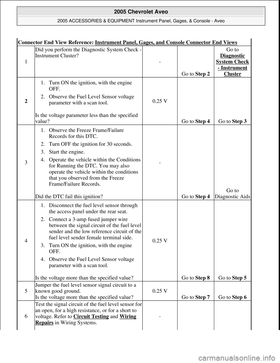
Connector End View Reference: Instrument Panel, Gages, and Console Connector End Views
1
Did you perform the Diagnostic System Check -
Instrument Cluster?
-
Go to Step 2
Go to
Diagnostic
System Check
- Instrument
Cluster
2
1. Turn ON the ignition, with the engine
OFF.
2. Observe the Fuel Level Sensor voltage
parameter with a scan tool.
Is the voltage parameter less than the specified
value?
0.25 V
Go to Step 4 Go to Step 3
3
1. Observe the Freeze Frame/Failure
Records for this DTC.
2. Turn OFF the ignition for 30 seconds.
3. Start the engine.
4. Operate the vehicle within the Conditions
for Running the DTC. You may also
operate the vehicle within the conditions
that you observed from the Freeze
Frame/Failure Records.
Did the DTC fail this ignition?
-
Go to Step 4
Go to
Diagnostic Aids
4
1. Disconnect the fuel level sensor through
the access panel under the rear seat.
2. Connect a 3-amp fused jumper wire
between the signal circuit of the fuel level
sender and the low reference circuit of the
fuel level sender female terminal side.
3. Turn ON the ignition, with the engine
OFF.
4. Observe the Fuel Level Sensor voltage
parameter with a scan tool.
Is the voltage more than the specified value?
0.25 V
Go to Step 8 Go to Step 5
5
Jumper the fuel level sensor signal circuit to a
known good ground.
Is the voltage more than the specified value?
0.25 V
Go to Step 7 Go to Step 6
6
Test the signal circuit of the fuel level sensor for
an open, for a high resistance, or for a short to
voltage. Refer to Circuit Testing
and Wiring
Repairs in Wiring Systems.
-
2005 Chevrolet Aveo
2005 ACCESSORIES & EQUIPMENT Instrument Panel, Gages, & Console - Aveo
Microsoft
Friday, July 31, 2009 1:07:02 PMPage 23 © 2005 Mitchell Repair Information Company, LLC.
Page 4317 of 5127

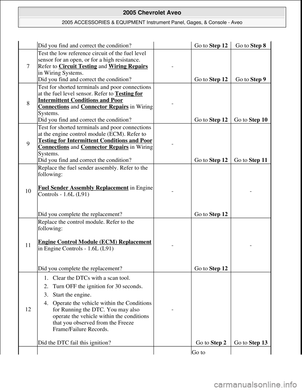
Did you find and correct the condition?Go to Step 12 Go to Step 8
7
Test the low reference circuit of the fuel level
sensor for an open, or for a high resistance.
Refer to Circuit Testing
and Wiring Repairs
in Wiring Systems.
Did you find and correct the condition?-
Go to Step 12 Go to Step 9
8
Test for shorted terminals and poor connections
at the fuel level sensor. Refer to Testing for
Intermittent Conditions and Poor
Connections and Connector Repairsin Wiring
Systems.
Did you find and correct the condition?-
Go to Step 12 Go to Step 10
9
Test for shorted terminals and poor connections
at the engine control module (ECM). Refer to
Testin
g for Intermittent Conditions and Poor
Connections and Connector Repairsin Wiring
Systems.
Did you find and correct the condition?-
Go to Step 12 Go to Step 11
10
Replace the fuel sender assembly. Refer to the
following:
Fuel Sender Assembly Replacement
in Engine
Controls - 1.6L (L91)
Did you complete the replacement?-
Go to Step 12
-
11
Replace the control module. Refer to the
following:
Engine Control Module (ECM) Replacement
in Engine Controls - 1.6L (L91)
Did you complete the replacement?-
Go to Step 12
-
12
1. Clear the DTCs with a scan tool.
2. Turn OFF the ignition for 30 seconds.
3. Start the engine.
4. Operate the vehicle within the Conditions
for Running the DTC. You may also
operate the vehicle within the conditions
that you observed from the Freeze
Frame/Failure Records.
Did the DTC fail this ignition?
-
Go to Step 2 Go to Step 13
Go to
2005 Chevrolet Aveo
2005 ACCESSORIES & EQUIPMENT Instrument Panel, Gages, & Console - Aveo
Microsoft
Friday, July 31, 2009 1:07:02 PMPage 24 © 2005 Mitchell Repair Information Company, LLC.
Page 4319 of 5127

The control module stores the DTC information into memory when the diagnostic runs and fails.
The malfunction indicator lamp (MIL) will not illuminate.
The control module records the operating conditions at the time the diagnostic fails. The control module
stores this information in the Failure Records.
The driver information center, if equipped, may display a message.
Conditions for Clearing the DTC
A current DTC Last Test Failed clears when the diagnostic runs and passes.
A history DTC clears after 40 consecutive warm-up cycles, if no failures are reported by this or any other
non-emission related diagnostic.
Clear the DTC with a scan tool.
Test Description
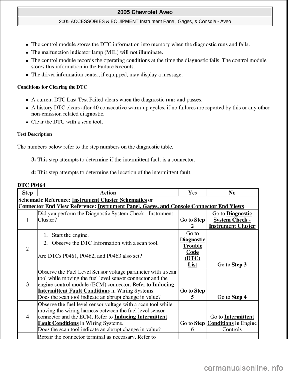
The numbers below refer to the step numbers on the diagnostic table.
3: This step attempts to determine if the intermittent fault is a connector.
4: This step attempts to determine the location of the intermittent fault.
DTC P0464
StepActionYesNo
Schematic Reference: Instrument Cluster Schematics or
Connector End View Reference: Instrument Panel, Gages, and Console Connector End Views
1
Did you perform the Diagnostic System Check - Instrument
Cluster?
Go to Step
2
Go to Diagnostic
System Check -
Instrument Cluster
2
1. Start the engine.
2. Observe the DTC Information with a scan tool.
Are DTCs P0461, P0462, and P0463 also set?Go to
Dia
gnostic
Trouble
Code
(DTC)
List Go to Step 3
3
Observe the Fuel Level Sensor voltage parameter with a scan
tool while moving the fuel level sensor connector and the
engine control module (ECM) connector. Refer to Inducing
Intermittent Fault Conditions in Wiring Systems.
Does the scan tool indicate an abrupt change in value?Go to Step
5
Go to Step 4
4
Observe the fuel level sensor voltage with a scan tool while
moving the wiring harness between the fuel level sensor
connector and the ECM. Refer to Inducing Intermittent
Fault Conditions in Wiring Systems.
Does the scan tool indicate an abrupt change in value?Go to Step
6
Go to Intermittent
Conditionsin Engine
Controls
Repair the connector terminal as necessary. Refer to
2005 Chevrolet Aveo
2005 ACCESSORIES & EQUIPMENT Instrument Panel, Gages, & Console - Aveo
Microsoft
Friday, July 31, 2009 1:07:02 PMPage 26 © 2005 Mitchell Repair Information Company, LLC.
Page 4320 of 5127

SYMPTOMS - INSTRUMENT PANEL, GAGES AND CONSOLE
Symptom List
Refer to a symptom diagnostic procedure from the following list in order to diagnose the symptom:
Clock Malfunction
Engine Coolant Temperature Gage Inaccurate or Inoperative
Fuel Gage Inaccurate or Inoperative
Speedometer and/or Odometer Inaccurate or Inoperative
Chime Inoperative (Seat Belt) Seat belt
Door Open Warning Chime Inoperative
Key Reminder Chime Inoperative
DOOR OPEN WARNING CHIME INOPERATIVE
Door Open Warning Chime Inoperative
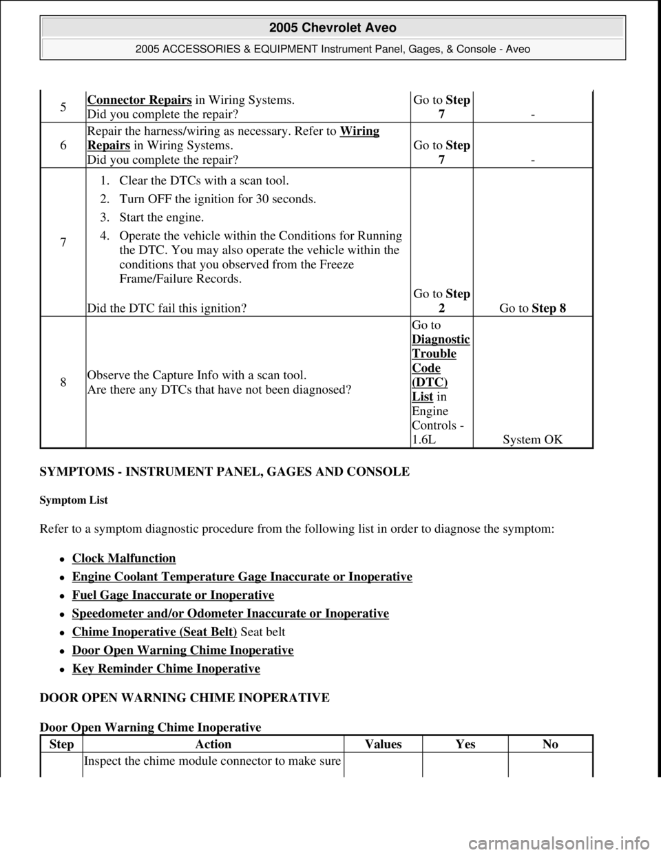
5Connector Repairs in Wiring Systems.
Did you complete the repair?Go to Step
7
-
6
Repair the harness/wiring as necessary. Refer to Wiring
Repairs in Wiring Systems.
Did you complete the repair?Go to Step
7
-
7
1. Clear the DTCs with a scan tool.
2. Turn OFF the ignition for 30 seconds.
3. Start the engine.
4. Operate the vehicle within the Conditions for Running
the DTC. You may also operate the vehicle within the
conditions that you observed from the Freeze
Frame/Failure Records.
Did the DTC fail this ignition?
Go to Step
2
Go to Step 8
8Observe the Capture Info with a scan tool.
Are there any DTCs that have not been diagnosed?
Go to
Dia
gnostic
Trouble
Code
(DTC)
List in
Engine
Controls -
1.6L
System OK
StepActionValuesYesNo
Inspect the chime module connector to make sure
2005 Chevrolet Aveo
2005 ACCESSORIES & EQUIPMENT Instrument Panel, Gages, & Console - Aveo
Microsoft
Friday, July 31, 2009 1:07:02 PMPage 27 © 2005 Mitchell Repair Information Company, LLC.