dimensions CHEVROLET CAMARO 1967 1.G Chassis Workshop Manual
[x] Cancel search | Manufacturer: CHEVROLET, Model Year: 1967, Model line: CAMARO, Model: CHEVROLET CAMARO 1967 1.GPages: 659, PDF Size: 114.24 MB
Page 3 of 659
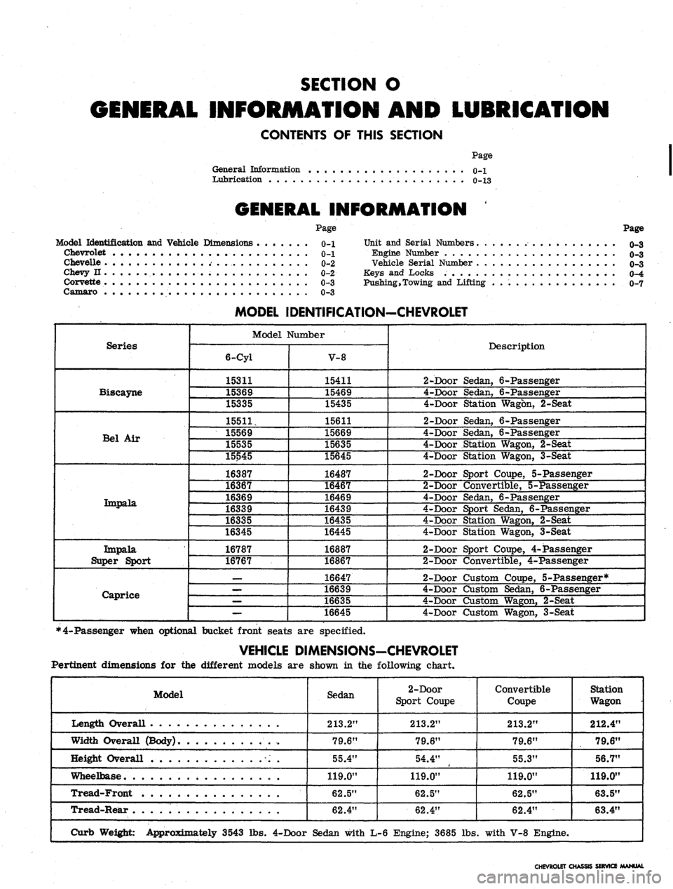
SECTION O
INFORMATION AND LUBRICATION
CONTENTS OF THIS SECTION
Page
General Information o-l
Lubrication 0-13
GENERAL INFORMATION
Model Identification and Vehicle Dimensions
Chevrolet
Chevelle
Chevy n
Corvette
Camaro
Page
0-1
0-1
0-2
0-2
0-3
0-3
Page
Unit and Serial Numbers o-3
Engine Number o-3
Vehicle Serial Number 0r3
Keys and Locks 0-4
Pushing,Towing and Lifting 0-7
Series
Biscayne
Bel Air
Tmpala.
Impala
Super Sport
Caprice
MODEL IDENTIFICATION-CHEVROLET
Model Number
6-Cyl
15311
15369
15335
15511,
15569
15535
15545
16387
16367
16369
16339
16335
16345
16787
16767
—
—
—
—
V-8
15411
15469
15435
15611
15669
15635
15645
16487
16467
16469
16439
16435
16445
16887
16867
16647
16639
16635
16645
Description
2-Door Sedan, 6-Passenger
4-Door Sedan, 6-Passenger
4-Door Station Wagon, 2-Seat
2-Door Sedan, 6-Passenger
4-Door Sedan, 6-Passenger
4-Door Station Wagon, 2-Seat
4-Door Station Wagon, 3-Seat
2-Door Sport Coupe, 5-Passenger
2-Door Convertible, 5-Passenger
4-Door Sedan, 6-Passenger
4-Door Sport Sedan, 6-Passenger
4-Door Station Wagon, 2-Seat
4-Door Station Wagon, 3-Seat
2-Door Sport Coupe, 4-Passenger
2-Door Convertible, 4-Passenger
2-Door Custom Coupe, 5-Passenger*
4-Door Custpm Sedan, 6-Passenger
4-Door Custom Wagon, 2-Seat
4-Door Custom Wagon, 3-Seat
*4-Passenger when optional bucket front seats are specified.
VEHICLE DIMENSIONS-CHEVROLET
Pertinent dimensions for the different models are shown in the following chart.
Model
Length Overall . .
Width Overall (Body)
Height Overall
Wheelbase
Tread-Front
Tread-Rear
Curb Weight: Approximately 3543 lbs.
Sedan
213.2"
79.6"
55.4"
119.0"
62.5"
62.4"
4-Door Sedan with
2-Door
Sport Coupe
213.2"
79.6"
54.4"
119.0"
62.5"
62.4"
L-6 Engine; 3685 lbs
Convertible
Coupe
213.2"
79.6"
55.3"
119.0"
62.5"
62.4"
. with V-8 Engine.
Station
Wagon
212.4"
79.6"
56.7"
119.0"
63.5"
63.4"
CHEVROLET CHASSIS SERVICE MANUAL
Page 4 of 659
GENERAL INFORMATION 0-2
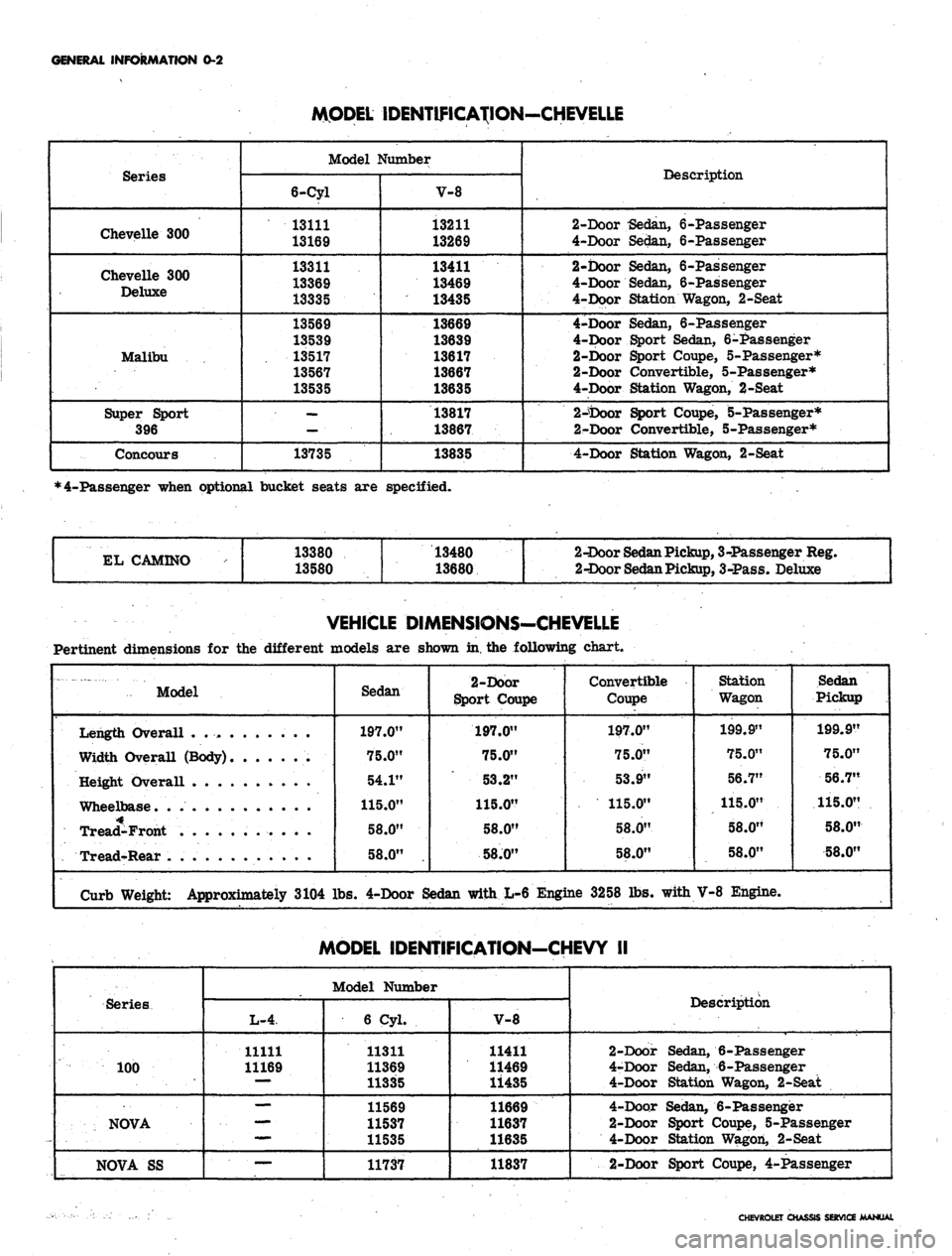
MODEL IDENTIFICATION-CHEVELLE
Series
Chevelle 300
Chevelle 300
Deluxe
Malibu
Super Sport
396
Concours
Model Number
6-Cyl
13111
13169
13311
13369
13335
13569
13539
13517
13567
13535
—
13735
V-8
13211
13269
13411
13469
13435
13669
13639
13617
13667
13635
13817
13867
13835
Description
2-Door -Sedan, 6-Passenger
4-Door Sedan, 6-Passenger
2-Door Sedan, 6-Passenger
4-Door Sedan, 6-Passenger
4-Door Station Wagon, 2-Seat
4-Door Sedan, 6-Passenger
4-Door Sport Sedan, 6-Passenger
2-Door Sport Coupe, 5-Passenger*
2-Door Convertible, 5-Passenger*
4-Door Station Wagon, 2-Seat
2-tooor Sport Coupe, 5-Passenger*
2-Door Convertible, 5-Passenger*
4-Door Station Wagon, 2-Seat
*4-Passenger when optional bucket seats are specified.
EL CAMINO
13380
13580
13480
13680
2-Door
Sedan
Pickup,
3-Passenger Reg.
2-Door
Sedan
Pickup,
3-Pass. Deluxe
VEHICLE DIMENSIONS-CHEVELLE
Pertinent dimensions for the different models are shown in, the following chart.
Model
Sedan
197.0"
75.0"
54.1"
115.0"
58.0"
58.0"
2-Door
Sport Coupe
197.0"
75.0"
53.2"
115.0"
58.0"
58J0"
Convertible
Coupe
197.0"
75.0"
53.9"
115.0"
58.0"
58.0"
Station
Wagon
199.9"
75.0"
56.7"
115.0"
58.0"
58.0"
Sedan
Pickup
199.9"
75.0"
56.7"
115.0"
58.0"
58.0"
Length Overall .
Width Overall (Body)
Height Overall . . .
Wheelbase. .
Tread-Front
Tread-Rear .
Curb Weight: Approximately 3104 lbs. 4-Door Sedan with L-6 Engine 3258 lbs. with V-8 Engine.
MODEL IDENTIFICATION-CHEVY II
Series
100
NOVA
NOVA SS
Model Number
L-4
11111
11169
mmm.
—
6 Cyl.
11311
11369
11335
11569
11537
11535
11737
V-8
11411
11469
11435
11669
11637
11635
11837
Description
2-Door Sedan, 6-Passenger
4-Door Sedan, 6-Passenger
4-Door Station Wagon, 2-Seat
4-Door Sedan, 6-Passenger
2-Door Sport Coupe, 5-Passenger
4-Door Station Wagon, 2-Seat
2-Door Sport Coupe, 4-Passenger
CHEVROLET CHASSIS SERVICE MANUAL
Page 5 of 659
GENERAL INFORMATION 0-3
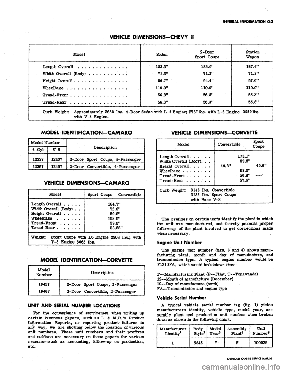
VEHICLE DIMENSIONS-CHEVY II
Model
Length Overall
Width Overall (Body) . . . .
Height Overall
Wheelbase
Tread-Front
Tread-Rear . . .
Sedan
183.0"
71.3"
56.7"
110.0"
56.8"
56.3"
2-Door
Sport Coupe
183.0"
71.3"
54.4"
110.0"
56.8"
56.3"
Station
Wagon
187.4"
71.3"
57.6"
110.0"
56.3"
55.8"
Curb Weight: Approximately 2668 lbs. 4-Door Sedan with L-4 Engine; 2767
lbs.
with L-6 Engine; 2959lbs.
with V-8 Engine.
MODEL IDENTIFICATION-CAMARO
VEHICLE DIMENSIONS-CORVEnE
Model Number
6-Cyl
12337
12367
V-8
12437
12467
Description
2-Door Sport Coupe, 4-Passenger
2-Door Convertible, 4-Passenger
VEHICLE DIMENSIONS-CAMARO
Model
Length Overall .....
Width Overall (Body) . .
Height Overall
Wheelbase
Tread-Front
Tread-Rear
Sport Coupe
Convertible
184.7"
72.6"
50:8"
108.0"
59.0"
58.88"
Weight: Sport Coupe with L6 Engine 2908 lbs.; with
V-8 Engine 3063 lbs.
MODEL IDENTIFICATION-CORVETTE
Model
Number
19437
19467
Description
2-Door Sport Coupe, 2-Passenger
2-Door Convertible, 2-Passenger
UNIT AND SERIAL NUMBER LOCATIONS
For the convenience of servicemen when writing up
certain business papers, such as L. & M.R.'s Product
Information Reports, or reporting product failures in
any way, we are showing below the location of various
unit numbers. These unit numbers and their prefixes
and suffixes are necessary on these papers for various
reasons—such as accounting, follow-up on production,
etc.
Model
Length Overall
Width Overall (Body). . .
Height Overall.
Wheelbase
Tread-Front
Tread-Rear .
Convertible
Sport
Coupe
175.1"
69.6"
49.8"
49.6"
98.0"
56.8"
57.6"
Curb Weight: 3145 lbs. Convertible
3135 lbs. Sport Coupe
with Base V-8
The prefixes on certain units identify the plant in which
the unit was manufactured, and thereby permits proper
follow-up of the plant involved to get corrections made
when necessary.
Engine Unit Number
The engine unit number (figs. 3 and 4) shows manu-
facturing plant, month and day of manufacture, and
transmission type. A typical engine number would be
F1210FA, which would breakdown thus:
F~Manufacturing Plant (F—Flint, T—Tonawanda)
12—Month of manufacture (December)
10—Day of manufacture (tenth)
FA—Transmission and engine type
Vehicle Serial Number
A typical vehicle serial number tag (fig. 1) yields
manufacturers identity, vehicle type, model year, as-
sembly plant and production unit number when broken
down as shown in the following chart.
Manufacturer
Identity1
1
Body
Style2
5645
Model
Year8
7
Assembly
Plant*
F
Unit
Number5
100025
CHEVROLET CHASSIS SERVICE /MANUAL
Page 161 of 659
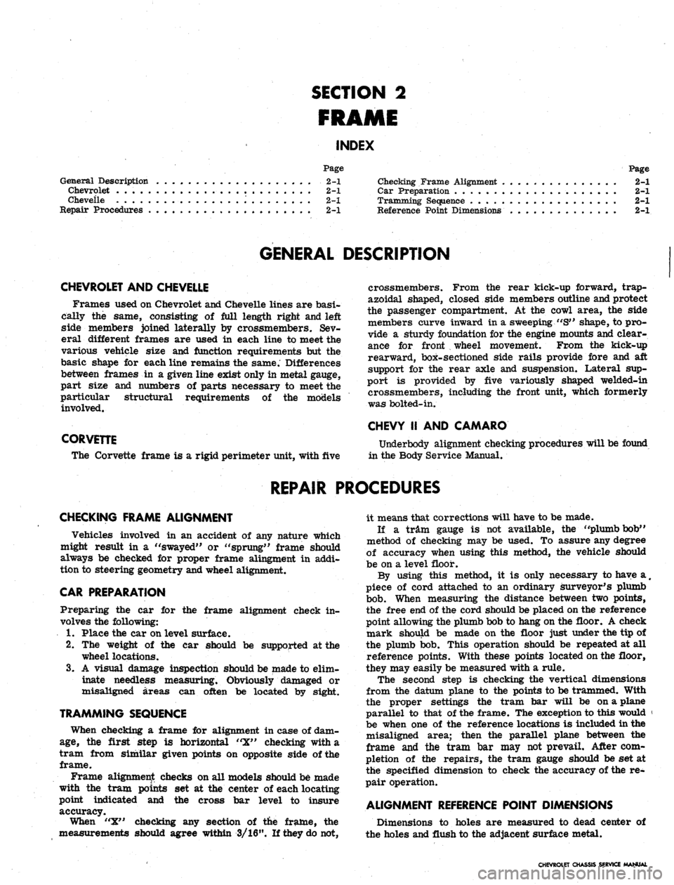
SECTION 2
FRAME
INDEX
Page
General Description 2-1
Chevrolet 2-1
Cheveile '. 2-1
Repair Procedures 2-1
Page
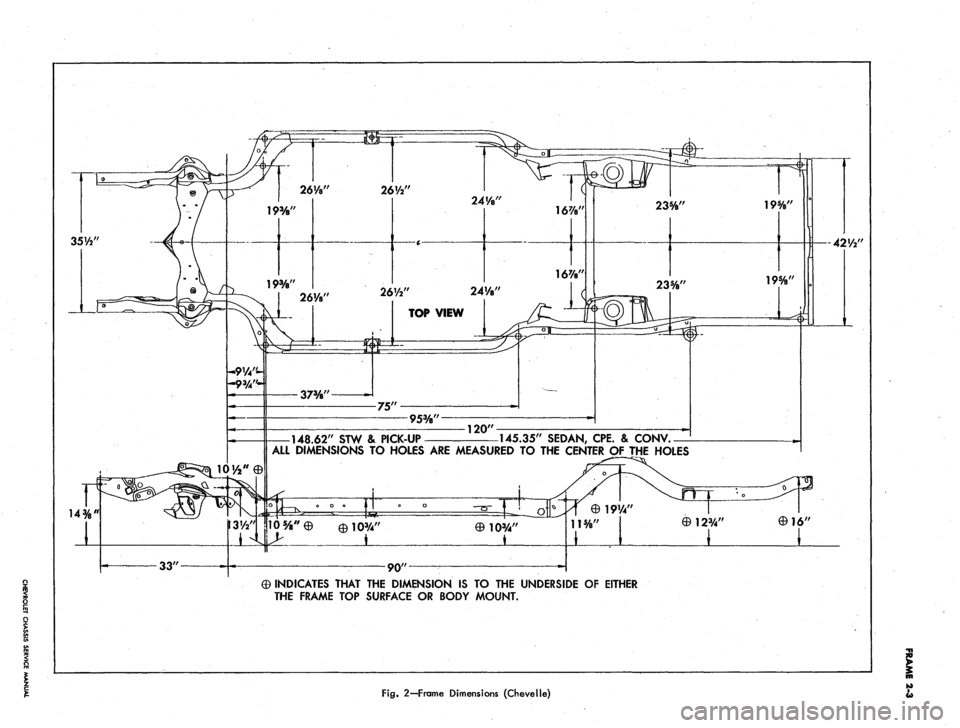
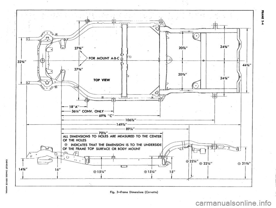
Checking Frame Alignment 2-1
Car Preparation 2-1
Tramming Sequence 2-1
Reference Point Dimensions 2-1
GENERAL DESCRIPTION
CHEVROLET AND CHEVELLE
Frames used on Chevrolet and Cheveile lines are basi-
cally the same, consisting of full length right and left
side members joined laterally by crossmembers. Sev-
eral different frames are used in each line to meet the
various vehicle size and function requirements but the
basic shape for each line remains the same. Differences
between frames in a given line exist only in metal gauge,
part size and numbers of parts necessary to meet the
particular structural requirements of the models
involved.
CORVETTE
The Corvette frame is a rigid perimeter unit, with five
crossmembers. From the rear kick-up forward, trap-
azoidal shaped, closed side members outline and protect
the passenger compartment. At the cowl area, the side
members curve inward in a sweeping "S" shape, to pro-
vide a sturdy foundation for the engine mounts and clear-
ance for front wheel movement. From the kick-up
rearward, box-sectioned side rails provide fore and aft
support for the rear axle and suspension. Lateral sup-
port is provided by five variously shaped welded-in
crossmembers, including the front unit, which formerly
was bolted-in.
CHEVY II AND CAMARO
Underbody alignment checking procedures will be found
in the Body Service Manual.
REPAIR PROCEDURES
CHECKING FRAME ALIGNMENT
Vehicles involved in an accident of any nature which
might result in a "swayed" or "sprung" frame should
always be checked for proper frame alingment in addi-
tion to steering geometry and wheel alignment.
CAR PREPARATION
Preparing the car for the frame alignment check in-
volves the following:
1.
Place the car on level surface.
2.
The weight of the car should be supported at the
wheel locations.
3.
A visual damage inspection should be made to elim-
inate needless measuring. Obviously damaged or
misaligned areas can often be located by sight.
TRAMMING SEQUENCE
When checking a frame for alignment in case of dam-
age,
the first step is horizontal "X" checking with a
tram from similar given points on opposite side of the
frame.
Frame alignment checks on all models should be made
with the tram points set at the center of each locating
point indicated and the cross bar level to insure
accuracy.
When "X" checking any section of the frame, the
measurements should agree within 3/16". If they do not,
it means that corrections will have to be made.
If a tram gauge is not available, the "plumb bob"
method of checking may be used. To assure any degree
of accuracy when using this method, the vehicle should
be on a level floor.
By using this method, it is only necessary to have a
#
piece of cord attached to an ordinary surveyor's plumb
bob.
When measuring the distance between two points,
the free end of the cord should be placed on the reference
point allowing the plumb bob to hang on the floor. A check
mark should be made on the floor just under the tip of
the plumb bob. This operation should be repeated at all
reference points. With these points located on the floor,
they may easily be measured with a rule.
The second step is checking the vertical dimensions
from the datum plane to the points to be trammed. With
the proper settings the tram bar will be on a plane
parallel to that of the frame. The exception to this would '
be when one of the reference locations is included in the
misaligned area; then the parallel plane between the
frame and the tram bar may not prevail. After com-
pletion of the repairs, the tram gauge should be set at
the specified dimension to check the accuracy of the re-
pair operation.
ALIGNMENT REFERENCE POINT DIMENSIONS
Dimensions to holes are measured to dead center of
the holes and flush to the adjacent surface metal.
CHEVROLET CHASSIS SERVICE MANUAL
Page 162 of 659
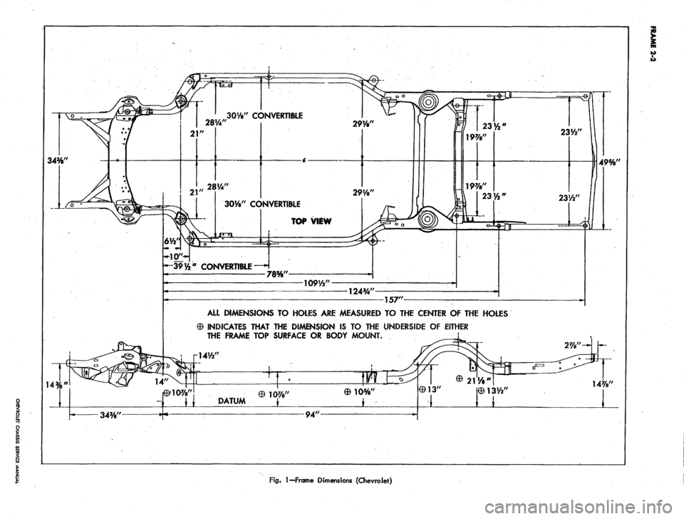
To"
34%"
14%"
21
28%"
" CONVERTIBLE
21
2914"
28%"
30y8" CONVERTIBLE
TOP VIEW
29V8"
—39 y2" CONVERTIBLE —H
78%"
109Vr2"
124%"
157"
ALL DIMENSIONS TO HOLES ARE MEASURED TO THE CENTER OF THE HOLES
0 INDICATES THAT THE DIMENSION IS TO THE UNDERSIDE OF EITHER
THE FRAME TOP SURFACE OR BODY MOUNT.
141/2"
DATUM
©10%"
231/*'
23W
L
49%'
14%'
34%"
94'
Fig.
1—Frame Dimensions (Chevrolet)
Page 163 of 659
35%*
14%
26VV
26V2"
24VB"
16%'
16%'
26l/s'/
-9V4"-
10'/a"
0
26V2" 24V8"
TOP
VIEW
37W
75"
95%"
148.62"
STW & PICK-UP
120"
235/8"
145.35"
SEDAN,
CPE.
&
CONV.
ALL
DIMENSIONS
TO
HOLES
ARE
MEASURED
TO THE
CENTER
OF
THE
HOLES
eio%"
L_
©123/4"
19%"
195/8"
-42'/2"
33"
90"
0 INDICATES THAT
THE
DIMENSION
IS TO THE
UNDERSIDE
OF
EITHER
THE FRAME
TOP
SURFACE
OR
BODY MOUNT.
Fig.
2—Frame Dimensions (Chevelle)
I
Page 164 of 659
FOR MOUNT A-B-C
18'A"
36V4"
CONV. ONLY
69%
JIC"
ALL DIMENSIONS TO HOLES ARE MEASURED TO THE CENTER
OF THE HOLES
0 INDICATES THAT THE DIMENSION IS TO THE UNDERSIDE
OF THE FRAME TOP SURFACE OR BODY MOUNT
Fig.
3—Frame Dimensions (Corvette)
Page 180 of 659
FRONT SUSPENSION 3-16
available the following procedure may also be
used (fig. 22-Alternate Method).
1.
Support car on suitable hoist or jack (so control
arms may swing free) and remove the wheel and
tire assembly, shock absorber, and stabilizer link
at control arm.
2.
Place suitable jack stand under the lower control
arm cross shaft.
3.
Follow Steps 2-5 as outlined on previous page.
4.
Turn head of tool screw to partially compress
spring.
5. Remove the three control arm cross shaft attaching
bolts,
washers and nuts.
6. Carefully lower jack stand and if necessary increase
compression on spring and when coil spring is out of
its upper seat, relax tension on spring (fig. 22).
7. By using a pry bar to assist, if necessary, remove
the coil spring from the lower control arm.
8. Installation is the reverse of the above procedure.
Carefully follow instructions for installing spring
tool.
LOWER CONTROL ARM SPHERICAL JOINT
Chevrolet, Chevelle, Comoro and Corvette
Inspection
The lower control arm spherical joint should be re-
placed whenever wear is indicated in the upper joint
inspection.
NOTE: The lower control arm spherical joint
is a loose fit in the assembly when not connected
to the steering knuckle.
Only if inspection of each upper joint indicates them
both to be within limits, inspect each lower joint for ex-
cessive wear as follows:
1.
After reconnecting upper joints to steering knuckles,
support vehicle weight on wheels or wheel hubs.
2.
With outside micrometer or caliper, measure dis-
tance from top of lubrication fitting to bottom of ball
stud, and record the dimensions for each side.
3.
Then support vehicle weight at outer end of each
lower control arm, so that wheels or wheel hubs are
free,
then repeat Step 2.
4.
If the difference in dimensions on either side is
greater than 1/16" (.0625"), the joint is excessively
worn and both lower joints should be replaced.
If inspection of lower spherical joints does not indicate
excessive wear, inspect further as follows:
5.
On Chevrolet Only--Examine lubrication hole in each
joint assembly after cleaning out hole. Look for evi-
dence of the liner partially or fully blocking lubrica-
tion opening. Such evidence indicates that liner is
disintegrating and that both lower spherical joints
should be replaced.
Another indication of lower spherical joint excessive
wear is indicated when difficulty is experienced when
lubricating the joint. If the liner has worn to the point
where the lubrication grooves in the liner have worn
away, then abnormal pressure is required to force lubri-
cant through the joint. This is another reason to recom-
mend replacement of both lower joints.
If the above inspections do not indicate any reason for
spherical joint replacements, test the torque tightness of
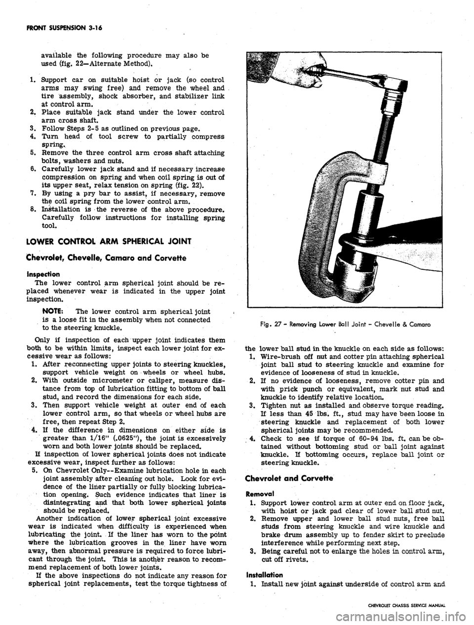
Fig. 27 - Removing Lower Ball Joint - Chevelle
&
Camaro
the lower ball stud in the knuckle on each side as follows:
1.
Wire-brush off nut and cotter pin attaching spherical
joint ball stud to steering knuckle and examine for
evidence of looseness of stud in knuckle.
2.
If no evidence of looseness, remove cotter pin and
with prick punch or equivalent, mark nut stud and
knuckle to identify relative location.
3.
Tighten nut as installed and observe torque reading.
If less than 45 lbs. ft., stud may have been loose in
steering knuckle and replacement of both lower
spherical joints may be recommended.
4.
Check to see if torque of 60-94 lbs. ft. can be ob-
tained without bottoming stud or ball joint against
knuckle. If bottoming occurs, replace ball joint or
steering knuckle.
Chevrolet and Corvette
Removal
1.
Support lower control arm at outer end on floor jack,
with hoist or jack pad clear of lower ball stud nut.
2.
Remove upper and lower ball stud nuts, free ball
studs from steering knuckle and wire knuckle and
brake drum assembly up to fender skirt to preclude
interference while performing next step.
3.
Being careful not to enlarge the holes in control arm,
cut off rivets.
Installation
1.
Install new joint against underside of control arm and
CHEVROLET CHASSIS SERVICE MANUAL
Page 214 of 659
REAR SUSPENSION AND DRIVE LINE 4-24
4
i*
5
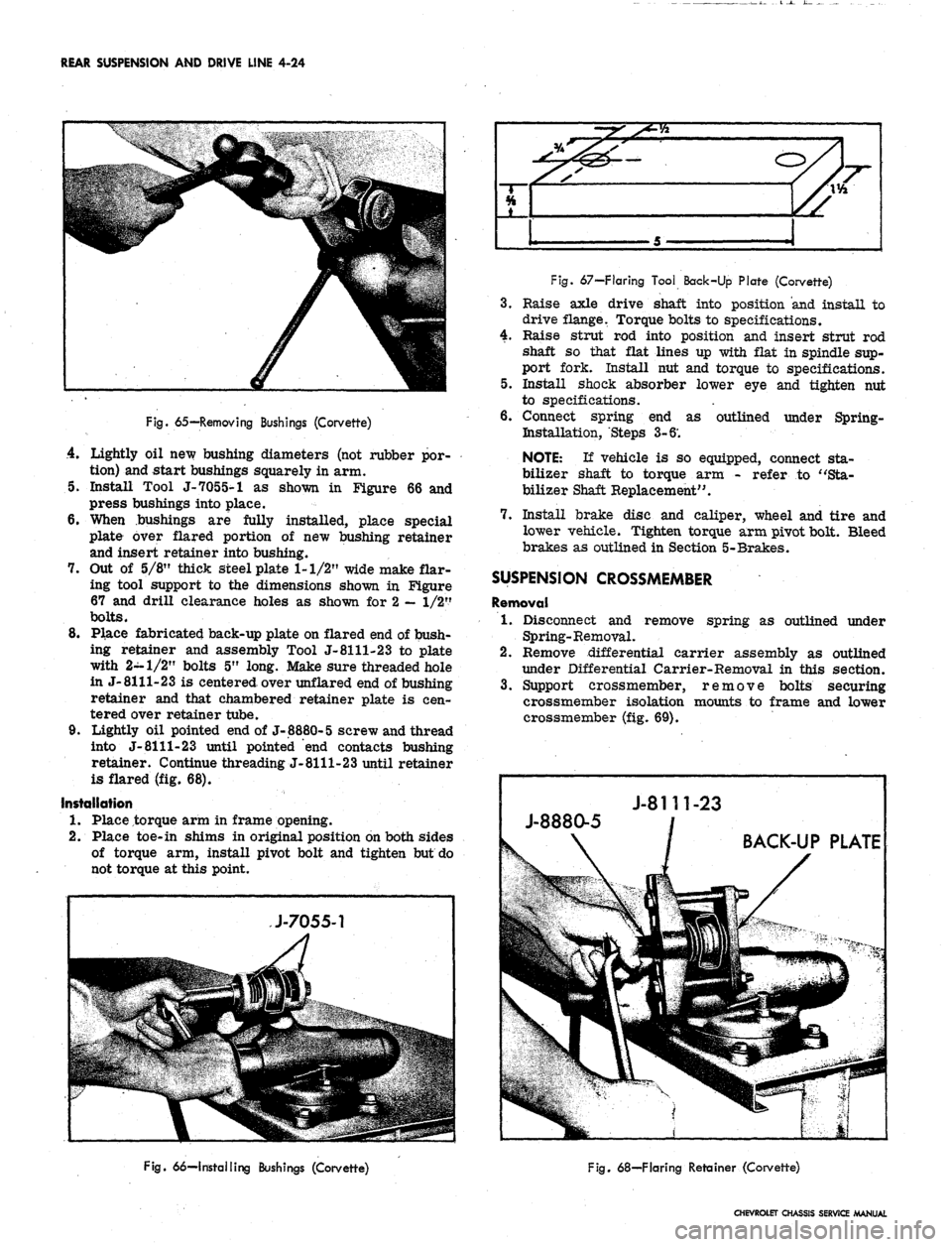
Fig.
65—Removing Bushings (Corvette)
4.
Lightly oil new bushing diameters (not rubber por-
tion) and start bushings squarely in arm.
5. Install Tool J-7055-1 as shown in Figure 66 and
press bushings into place.
6. When bushings are fully installed, place special
plate over flared portion of new bushing retainer
and insert retainer into bushing.
7. Out of 5/8" thick steel plate 1-1/2" wide make flar-
ing tool support to the dimensions shown in Figure
67 and drill clearance holes as shown for 2
—
1/2"
bolts.
8. Place fabricated back-up plate on flared end of bush-
ing retainer and assembly Tool J-8111-23 to plate
with 2-1/2" bolts 5" long. Make sure threaded hole
in J-8111-23 is centered over unflared end of bushing
retainer and that chambered retainer plate is cen-
tered over retainer tube.
9. Lightly oil pointed end of J-8880-5 screw and thread
into J-
8111-23
until pointed "end contacts bushing
retainer. Continue threading J-8111-23 until retainer
is flared (fig. 68).
Installation
1.
Place torque arm in frame opening.
2.
Place toe-in shims in original position on both sides
of torque arm, install pivot bolt and tighten but do
not torque at this point.
Fig.
67—Flaring Tool Back-Up Plate (Corvette)
3.
Raise axle drive shaft into position and install to
drive flange. Torque bolts to specifications.
4.
Raise strut rod into position and insert strut rod
shaft so that flat lines up with flat in spindle sup-
port fork. Install nut and torque to specifications.
5. Install shock absorber lower eye and tighten nut
to specifications.
6. Connect spring end as outlined under Spring-
Bistallation, Steps 3-6'.
NOTE:
If vehicle is so equipped, connect sta-
bilizer shaft to torque arm - refer to "Sta-
bilizer Shaft Replacement".
7. Install brake disc and caliper, wheel and tire and
lower vehicle. Tighten torque arm pivot bolt. Bleed
brakes as outlined in Section 5-Brakes.
SUSPENSION CROSSMEMBER
Removal
1.
Disconnect and remove spring as outlined under
Spring-Removal.
2.
Remove differential carrier assembly as outlined
under Differential Carrier-Removal in this section.
3.
Support crossmember, remove bolts securing
crossmember isolation mounts to frame and lower
crossmember (fig. 69).
Fig.
66—Installing Bushings (Corvette)
Fig.
68—Flaring Retainer (Corvette)
CHEVROLET CHASSIS SERVICE MANUAL
Page 500 of 659
CHASSIS SHEET METAL 11-13
HOOD ADJUSTMENT
The alignment of the hood in relation
to*
other sheet
metal parts is controlled by the position of the hood
hinges and the height of the two bumpers, located one at
each end of the radiator support. The adjustments at
the hood latch must be made after the hinges and bumpers
are positioned to yield the dimensions shown in Figure
17.
Latch adjustments are made so that effort required
to open and close the hood is reasonable, and hood align-
ment obtained by hinge and bumper adjustment is main-
tained when the hood is closed. Note that the hood latch
is not designed or intended to correct basic hood align-
ment faults.
To align the hood and lock, proceed as follows:
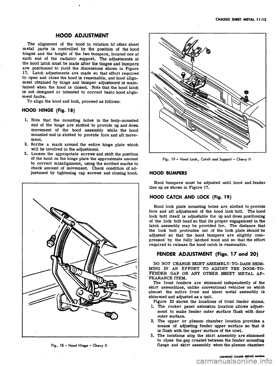
HOOD HINGE (Fig. 18)
1.
Note that the mounting holes in the body-mounted
end of the hinge are slotted to provide up and down
movement of the hood assembly while the hood
mounted end is slotted to provide fore and aft move-
ment.
2.
Scribe a mark around the entire hinge plate which
will be involved in the adjustment.
3.
Loosen the appropriate screws and shift the position
of the hood on the hinge plate the approximate amount
to correct misalignment, using the scribed marks to
check amount of movement. Check condition of ad-
justment by tightening cap screws and closing hood.
Fig.
18 - Hood Hinge - Chevy II
Fig.
19 - Hood Lock, Catch and Support - Chevy II
HOOD BUMPERS
Hood bumpers must be adjusted until hood and fender
line up as shown in Figure 17.
HOOD CATCH AND LOCK (Fig. 19)
Hood lock plate mounting holes are slotted to provide
fore and aft adjustment of the hood lock bolt. The hood
lock bolt itself is adjustable for up and down positioning
of the lock bolt head so that its proper engagement in the
latch assembly may be provided for. The distance that
the lock bolt protrudes out of the lock plate should be
adjusted so that the hood bumpers are slightly com-
pressed by the fully latched hood and so that the effort
required to release the hood catch is reasonable.
FENDER ADJUSTMENT (Figs. 17 and 20)
DO NOT CHANGE SKIRT ASSEMBLY-TO-DASH SHIM-
MING IN AN EFFORT TO ADJUST THE DOOR-TO-
FENDER GAP OR ANY OTHER SHEET METAL AP-
PEARANCE ITEM.
The front fenders are shimmed independently of the
skirt assemblies, unlike conventional- vehicles on which
almost the entire front end sheet metal assembly is
shimmed and adjusted as a unit.
Figure 20 shows the locations of front fender shims.
1.
The rocker panel extension location allows adjust-
ment to make fender outer surface flush with door
outer surface.
2.
The upper or plenum chamber location provides a
means of adjusting fender upper surface so that it
is flush with the upper surface of the cowl.
3.
The locations atop the skirt assembly are shimmed
to close the gap created between the fender mounting
flange and skirt assembly when the plenum chamber
CHEVROLET CHASSIS SWVICE MANUAL