clock CHEVROLET CAMARO 1967 1.G Chassis Workshop Manual
[x] Cancel search | Manufacturer: CHEVROLET, Model Year: 1967, Model line: CAMARO, Model: CHEVROLET CAMARO 1967 1.GPages: 659, PDF Size: 114.24 MB
Page 26 of 659
HEATER AND AIR CONDITIONING 1A-3
linkage of this lever which will provide partial airflow
only to the defroster duct and which should be used for,
all normal defogging operations.
CORVETTE
Heater components are attached to the dash panel on
the right side of the vehicle with the air inlet assembly
on the engine side and the heater and air distributor
assemblies beneath the instrument panel within the pas-
senger compartment.
The heater operates on outside air only with the blower
receiving its air flow from the cowl vent plenum
chamber.
No water valve is utilized in the system. Therefore,
water flows through the heater core constantly while
the engine is running, keeping the core at maximum
temperature at all times.
Airflow through the system is shown in Figure 1.
Controls
Two knobs control all heater operations:
The FAN-TEMP knob is rotated to turn the blower
on and off and control blower speed and is pulled out
as desired to regulate heater temperature.
The AIR-DEF knob is the air on-and-off control as
well as the defroster control.
Temperature Damper: Door
At the heart of the heater operation is the temperature
damper door. Air from the blower follows parallel paths
through the distributor duct, with one path passing
through the heater core and the other path bypassing the
core.
The temperature damper door is placed in the duct
so that, when closed, the path of the heated air leaving
the heater core is blocked while the ambient air path
remains open. Positive closing of this door when no
heat is being called for is assured by a cam assembly
at the door operating lever. As the FAN-TEMP knob
is pulled out, the damper door is opened accordingly,
allowing varying proportions of heated air to mix with
the unheated airflow, thus providing heater outlet tem-
perature control. With the knob pulled fully out the
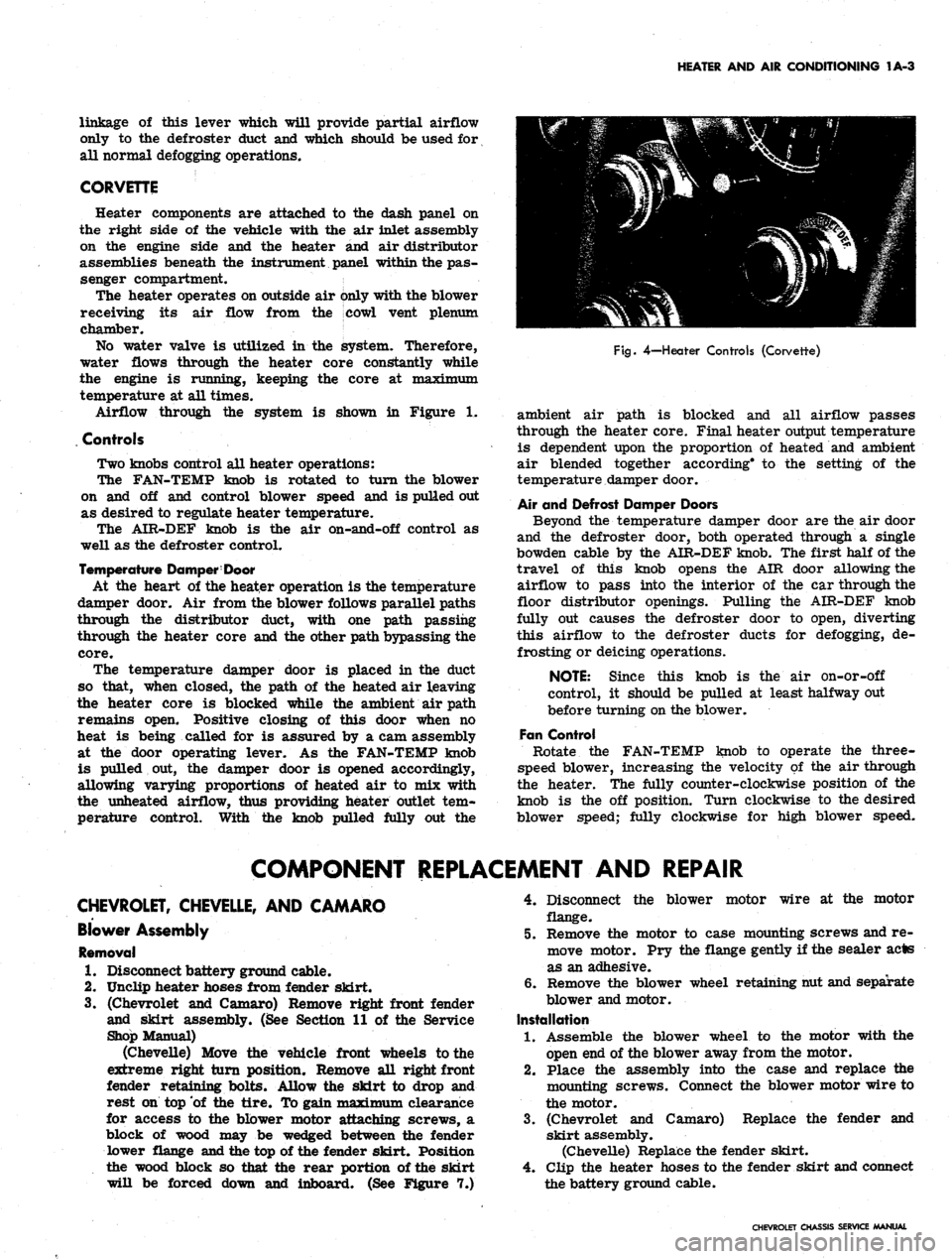
Fig.
4—Heater Controls (Corvette)
ambient air path is blocked and all airflow passes
through the heater core. Final heater output temperature
is dependent upon the proportion of heated and ambient
air blended together according* to the setting of the
temperature damper door.
Air and Defrost Damper Doors
Beyond the temperature damper door are the air door
and the defroster door, both operated through a single
bowden cable by the AIR-DEF knob. The first half of the
travel of this knob opens the AIR door allowing the
airflow to pass into the interior of the car through the
floor distributor openings. Pulling the AIR-DEF knob
fully out causes the defroster door to open, diverting
this airflow to the defroster ducts for defogging, de-
frosting or deicing operations.
NOTE: Since this knob is the air on-or-off
control, it should be pulled at least halfway out
before turning on the blower.
Fan Control
Rotate the FAN-TEMP knob to operate the three-
speed blower, increasing the velocity of the air through
the heater. The fully counter-clockwise position of the
knob is the off position. Turn clockwise to the desired
blower speed; fully clockwise for high blower speed.
COMPONENT REPLACEMENT AND REPAIR
CHEVROLET, CHEVELLE, AND CAMARO
Blower Assembly
Removal
1.
Disconnect battery ground cable.
2.
Unclip heater hoses from fender skirt.
3.
(Chevrolet and Camaro) Remove right front fender
and skirt assembly. (See Section 11 of the Service
Shop Manual)
(Chevelle) Move the vehicle front wheels to the
extreme right turn position. Remove all right front
fender retaining bolts. Allow the skirt to drop and
rest on top of the tire. To gain maximum clearance
for access to the blower motor attaching screws, a
block of wood may be wedged between the fender
lower flange and the top of the fender skirt. Position
the wood block so that the rear portion of the skirt
will be forced down and inboard. (See Figure 7.)
4.
Disconnect the blower motor wire at the motor
flange.
5.
Remove the motor to case mounting screws and re-
move motor. Pry the flange gently if the sealer acts
as an adhesive.
6. Remove the blower wheel retaining nut and separate
blower and motor.
Installation
1.
Assemble the blower wheel to the motor with the
open end of the blower away from the motor.
2.
Place the assembly into the case and replace the
mounting screws. Connect the blower motor wire to
the motor.
3.
(Chevrolet and Camaro) Replace the fender and
skirt assembly.
(Chevelle) Replace the fender skirt.
4.
Clip the heater hoses to the fender skirt and connect
the battery ground cable.
CHEVROLET CHASSIS SERVICE MANUAL
Page 44 of 659
HEATER AND AIR CONDITIONING 1A-21
"De-Fog"
Position
In the event that the front windshield should require
removal of a fogging condition, the owner at his option
may direct air to the windshield. The "De-Fog" position
directs part of the air to the windshield while retaining a
certain amount through the floor outlets. The temper-
ature of the air remains the same as it was prior to the
control being placed in the "De-Fog" position. Five
blower speeds are available. The temperature of the air
and the blower speed are selected by the automatic
controls and are dependent upon the in-car temperature.
"De-Ice" Position
The "De-Ice" position provides full heat with "Hi"
blower directing the entire airflow to the windshield to
melt ice. The automatic controls are completely defeated
and as a result, full heat with "Hi" blower are the only
conditions that can be received. The system will turn on
immediately in this position even though the engine
coolant might be cold.
General Information
Three start up conditions can be achieved with
Comfortron.
Weather
Cold
Method of Starting System
System starts as soon as engine coolant is
hot.
Hot System starts immediately when AC is
required.
Any System starts immediately in "De-Ice"
position.
UNIVERSAL SYSTEM
A self-contained unit, the dealer installed Universal
System operates on recirculated air only and entirely
independent of the vehicle heater. Recirculated inside air
is drawn into the unit, passed through the evaporator core
and into the car through the adjustable outlets in the
evaporator case. The entire unit mounts compactly
beneath the dash. Temperature control is by means of a
thermostatic switch.
The compressor used with the Universal System is
identical to that used for the Four-Season system except
for displacement. Underhood components are similar in
placement to the Four-Season system.
Controls
Universal system controls are the AIR knob controlling
the three speed blower motor switch and the TEMP knob
which controls the setting of the thermostatic switchi
Switch adjustment is covered elsewhere in this section.
When operating this system the Heater must be fully off.
CHEVY II ALL-WEATHER SYSTEM
The Chevy n All-Weather Air Conditioning System,
Figure 33, operates in conjunction with the heater to
provide a complete air conditioning system operating on
either outside air, recirculated air or a combination of
both. The cooling unit attaches to the heater distributor
and utilizes the heater blower. Several controls allow
full use of either the heating or cooling features of the
system. During marginal weather, it is possible to pro-
vide heated air at floor level and cooled air at breath
level.
A schematic view of the air conditioning underdash
components is provided in Figure 34 to aid in under-
standing airflow and control operation.
The evaporator assembly, located in the passenger
compartment attached directly to the heater distributor,
contains the evaporator core, expansion valve, thermo-
static switch and the air conditioning "ON" knob. The
thermostatic switch, utilized as the cooling control, feels
the temperature of the cooled air leaving the evaporator
core and turns the compressor on and off in accordance
with cooling needs. Refrigerant lines connect the evap-
orator assembly to the other system components located
in the engine compartment.
The six cylinder air conditioning compressor, com-
pletely field serviceable, is bracket-mounted to the
engine and is belt driven from the crankshaft pulley. A
muffler assembly, designed to eliminate compressor
pulsations is an integral part of the compressor con-
nector block. The condenser is mounted on the radiator
support just ahead of the engine radiator. The receiver-
dehydrator, with its sight glass, is located on the right
fender skirt.
Controls
Control of the air conditioning system is achieved
through the use of the heater control on the instrument
panel as well as the two knobs located on the air condi-
tioning unit itself (fig. 35).
Air Conditioning "ON" Knob
Labeled "Pull for Air Cond.", this knob diverts air-
flow from the floor distributor and through the air condi-
tioning unit. Initial movement of this knob also actuates a
switch, located at the damper door, which energizes the
compressor clutch thus putting the system into operation
and under the control of the thermostatic switch.
Temp-Cool Knob
This knob controls the thermostatic switch. Turn the
knob clockwise for more cooling, counter-clockwise for
less cooling.
Air Lever
This lever actuates the damper within the assembly
which chooses between recirculated air or outside air.
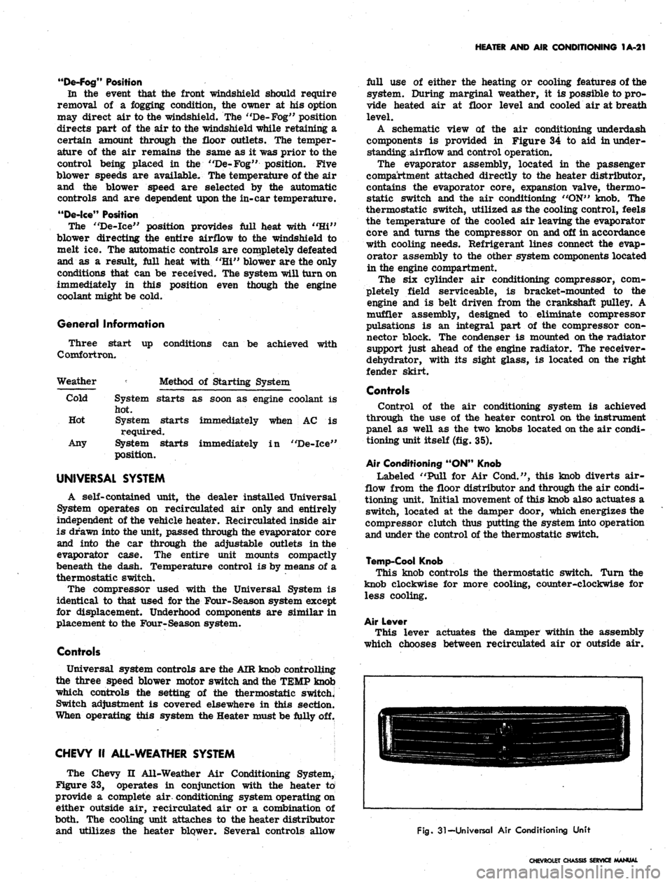
Fig.
31-Universal Air Conditioning Unit
CHEVROLET CHASSIS SERVICE MANUAL
Page 47 of 659
HEATER AND AIR. CONDITIONING 1A-24
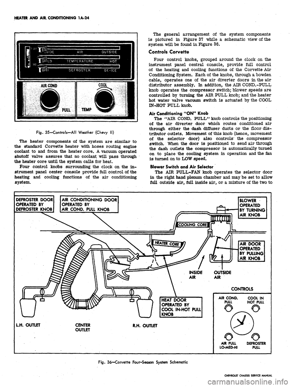
Fig. 35-Controls-AII Weather (Chevy II)
The heater components of the system are similar to
the standard Corvette heater with hoses routing engine
coolant to and from the heater core. A vacuum operated
shutoff valve assures that no coolant will pass through
the heater core until the system calls for heat.
Four control knobs surrounding the clock on the in-
strument panel center console provide full control of the
heating and cooling functions of the air conditioning
system.
The general arrangement of the system components
is pictured in Figure 37 while a schematic view of the
system will be found in Figure 36.
Controls Corvette
Four control knobs, grouped around the clock on the
instrument panel central console, provide full control
of the heating and cooling functions of the Corvette Air
Conditioning System. Each of the knobs, through a bowden
cable, operates one of the air diverter doors in the air
distributor assembly. In addition, the AIR COND.-PULL
knob operates the compressor switch; blower speeds are
controlled by turning the AIR PULL knob; and the heater
hot water valve vacuum switch is actuated by the COOL
IN-HQT PULL knob.
Air Conditioning "ON" Knob
The "AIR COND. PULL" knob controls the positioning
of the air diverter door which routes conditioned air
through either the dash diffuser ducts or the floor dis-
tributor outlets. Movement of this knob (hence, movement
of the selector door) also controls' the compressor
switch. When the door is positioned to send air through
the dash outlets the compressor is automatically turned
on to place the cooling system in operation and the fan
is turned on to LOW speed.
Blower Switch and Air Selector
The AIR PULL-FAN knob operates the selector door
in the right hand plenum chamber and may be set to allow
full outside air, full inside air, or a mixture of the two to
DEFROSTER DOOR
OPERATED BY
DEFROSTER KNOB
AIR CONDITIONING DOOR
OPERATED BY
AIR COND. PULL KNOB
BLOWER
OPERATED
BY TURNING
AIR KNOB
AIR DOOR
OPERATED
BY PULLING
AIR KNOB
OUTSIDE
AIR
CONTROLS
HEAT DOOR
OPERATED BY
COOL IN-HOT PULL
KNOB
L.H. OUTLET
CENTER
OUTLET
R.H. OUTLET
AIR COND.
PULL
COOL IN
HOT PULL
AIR PULL
LO-MED-HI
DEFROSTER
PULL
Fig.
36—Corvette Four-Season System Schematic
CHEVROLET CHASSIS SERVICE MANUAL
Page 49 of 659
HEATER AND AIR CONDITIONING 1A-26
clockwise for medium and high blower speed, as
desired. Low blower speed is automatic during
cooling operations.
4.
"Def-Pull". This knob should be pushed fully in.
Additional Cooling Hints
1.
The center barrel outlet in the dash may be rotated
to deflect air as desired or used to act as a shut off
door.
2.
The right and left ball outlets may be rotated to
deflect air in the direction desired. Each outlet has
a shut off valve operated by a knob approximately
4 in. inboard. When the knob is horizontal, the valve
is open.
3.
There are two (2) additional outlets in the bottom of
the ducts approximately 6" inboard from the valve
knobs. A rotating cover will open these outlets to
provide cool air for the feet if desired.
4.
When first entering a very warm car, open the
windows for a few minutes until the interior of the
car has cooled off.
Heating
1.
"Air Pull-Fan". Pull this knob fully out. Rotate
the knob clockwise for low, medium or high blower
speed as desired. If just a small amount of heat is
desired, leave the fan on low or medium speed and
regulate the temperature with the "Cool In-Hot Pull"
knob.
2.
"Air Cond-Pull". This knob should normally be
pushed fully in. However, during cool, damp days
it is possible, by pulling this knob fully out, to de-
humidify the air by passing it through the evaporator
core before reheating to the desired outlet
temperature.
3.
"Cool In-Hot Pull". Pull this knob out as far as
necessary to provide the temperature desired.
4.
"Def-Pull". Pull this knob all the way out for
maximum defrosting or de-icing. When the knob is
partly out, a portion of the hot air is used for de-
frosting and the balance is discharged through the
heater outlet.
GENERAL INFORMATION
In any vocation or trade, there are established proce-
dures and practices that have been developed after many
years of experience. In addition, occupational hazards
may be present that require the observation of certain
precautions or use of special tools and equipment. Ob-
serving the procedures, practices and precautions of
servicing refrigeration equipment will greatly reduce the
possibilities of damage to the customers' equipment as
well as virtually eliminate the element of hazard to the
serviceman.
PRECAUTIONS IN HANDLING REFRIGERANT-12
Refrigerant-12 is transparent and colorless in both the
gaseous and liquid state. It has a boiling point of 21.7^
below zero and, therefore, at all normal temperatures
and pressures it will be a vapor. The vapor is heavier
than air and is noninflammable, nonexplosive, non-
poisonous (except when in contact with an open flame)
and noncorrosive (except when in contact with water).
The following precautions in handling R-12 should be
observed at all times.
• All refrigerant drums are shipped with a heavy metal
screw cap. The purpose of the cap is to protect the
valve and safety plug from damage. It is good .prac-
tice to replace the cap after each use of the drum.
• If it is ever necessary to transport or carry a drum
or can of refrigerant in a car, keep it in the luggage
compartment. Refrigerant should not be exposed to
the radiant heat from the sun for the resulting in-
crease in pressure may cause the safety plug to
release or the drum or can to burst..
• Drums or disposable cans should never be subjected
to high temperature when adding refrigerant to the
system. In most instances, heating the drum or can
is required to raise the pressure in the container
higher than the pressure in the system during the
operation. It would be unwise to place the drum on a
gas stove, radiator or use a blow torch while pre-
paring for the charging operation, for a serious ac-
cident can result. Don't depend on the safety
plug - many drums have burst when the safety plug
failed.' Remember, high pressure means that great
forces are being exerted against the walls of the
container. A bucket of warm water, not over 125°F,
or warm wet rags around the container is all the heat
that is required.
• Do not weld or steam clean on or near the system.
Welding or steam cleaning can result in a dangerous
pressure buildup in the system.
• When filling a small drum from a large one, never
fill the drum completely. Space should always be
allowed above the liquid for expansion. If the drum
were completely full and the temperature was in-
creased, hydraulic pressure with its tremendous
force would result.
• Discharging large quantities of R-12 into a room can
usually be done safely as the vapor would produce
no ill effects, however, in the event of an accidental
rapid discharge of the system it is recommended
that inhalation of large quantities of R-12 be avoided.
This caution is especially important if the area con-
tains a flame producing device such as a gas heater.
While R-12 normally is nonpoisonous, heavy con-
centrations.. of it in contact with a live flame will
produce a toxic gas. The same gas will also attack
all bright metal surfaces.
• Protection of the eyes is of vital importance! When
working around a refrigerating system, an accident
may cause liquid refrigerant to hit the face. If the
eyes are protected with goggles or glasses, no
serious damage can result. Just remember, any
R-12 liquid that you can touch or that touches you is
at least 21.7"F. below zero. The eyeballs can't take
much of this temperature. If R-12 liquid should
strike the eyeballs, here is what to do:
1.
Keep calm.
2.
Do not rub the eyes! Splash the affected area with
quantities of cold water to gradually get the tem-
perature above the freezing point. The use of min-
eral, cod liver or an antiseptic oil is important in
CHEVROLET CHASSIS SERVICE MANUAL
Page 63 of 659
HEATER AND AIR CONDITIONING 1A-40
THERAAAL VACUUM
VALVE
TO ENGINE
VACUUM
SOURCE
VACUUM STORAGE
TANK
OUTSIDE AIR
DIAPHRAGM
MODE
DIAPHRAGM
VACUUM
RELAY
BLACK
DEFOG-DEICE
DIAPHRAGM
GREEN
BLACKj ||
|
BROWN
CONTROL
VALVE
Fig.
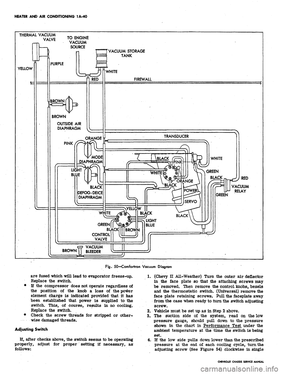
50—Comfortron Vacuum Diagram
are fused which will lead to evaporator freeze-up.
Replace the switch.
• If the compressor does not operate regardless of
the position of the knob a loss of the power
element charge is indicated provided that it has
been established that power is supplied to the
switch. This, of course, results in no cooling.
Replace the switch.
• Check the screw threads for stripped or other-
wise damaged threads.
Adjusting Switch
H, after checks above, the switch seems to be operating
properly,
follows:
adjust for proper setting if necessary, as
1.
(Chevy II All-Weather) Turn the outer air deflector
in the face plate so that the attaching screws may
be removed; Then remove the control knobs, bezels
and the thermostatic switch. (Universal) remove the
face plate retaining screws. Pull the faceplate away
from the case when ready to turn the switch adjusting
screw.
2.
Vehicle must be set up as in Step 2 above.
3.
The suction side of the system, read on the low
pressure gauge, should pull down to the pressure
shown in the chart in Performance Test under the
ambient temperature at the time the switch is being
set.
4.
If the low side pulls down lower than the prescribed
pressure at the end of each cooling cycle, turn the
adjusting screw (See Figure 54) clockwise in single
CHEVROLET CHASSIS SERVICE MANUAL
Page 64 of 659
HEATER
AND AIR
CONDITIONING
1A-41
OUTLET
1
TO EXPANSION
^
VALVE
TO
OIL
BLEED LINE
^ INLET
Fig.
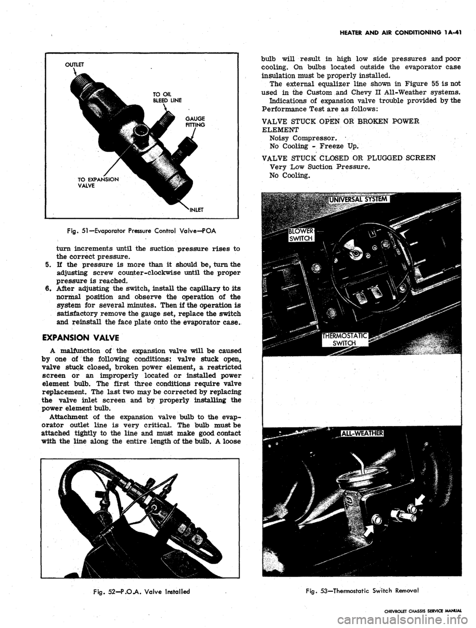
51—Evaporator Pressure Control Valve—POA
turn increments until
the
suction pressure rises
to
the correct pressure.
5.
If the
pressure
is
more than
it
should
be,
turn the
adjusting screw counter-clockwise until
the
proper
pressure
is
reached.
6. After adjusting
the
switch, install the capillary to
its
normal position
and
observe
the
operation
of the
system
for
several minutes. Then
if
the operation
is
satisfactory remove the gauge
set,
replace the switch
and reinstall the face plate onto the evaporator case.
EXPANSION VALVE
A malfunction
of the
expansion valve will
be
caused
by
one of the
following conditions: valve stuck open,
valve stuck closed, broken power element,
a
restricted
screen
or an
improperly located
or
installed power
element bulb.
The
first three conditions require valve
replacement.
The
last two may be corrected by replacing
the valve inlet screen
and by
properly installing
the
power element bulb.
Attachment
of the
expansion valve bulb
to the
evap-
orator outlet line
is
very critical.
The
bulb must be
attached tightly
to the
line
and
must make good contact
with
the
line along
the
entire length
of
the bulb. A loose
bulb will result
in
high
low
side pressures and poor
cooling.
On
bulbs located outside
the
evaporator case
insulation must be properly installed.
The external equalizer line shown
in
Figure
55 is
not
used
in the
Custom
and
Chevy
II
All-Weather systems.
Indications
of
expansion valve trouble provided by the
Performance Test are
as
follows:
VALVE STUCK OPEN
OR
BROKEN POWER
ELEMENT
Noisy Compressor.
•
No Cooling
-
Freeze
Up.
VALVE STUCK CLOSED
OR
PLUGGED SCREEN
Very Low Suction Pressure.
No Cooling.
Fig.
52-P.O.A. Valve Installed
Fig.
53—Thermostatic Switch Removal
CHEVROLET CHASSIS SERVICE MANUAL
Page 66 of 659
HEATER AND AIR CONDITIONING 1A-43
LOW PRESSURE
CONTROL
HIGH PRESSURE
CONTROL
3
VACUUM
CONTROL
4
FREON
CONTROL
Fig,
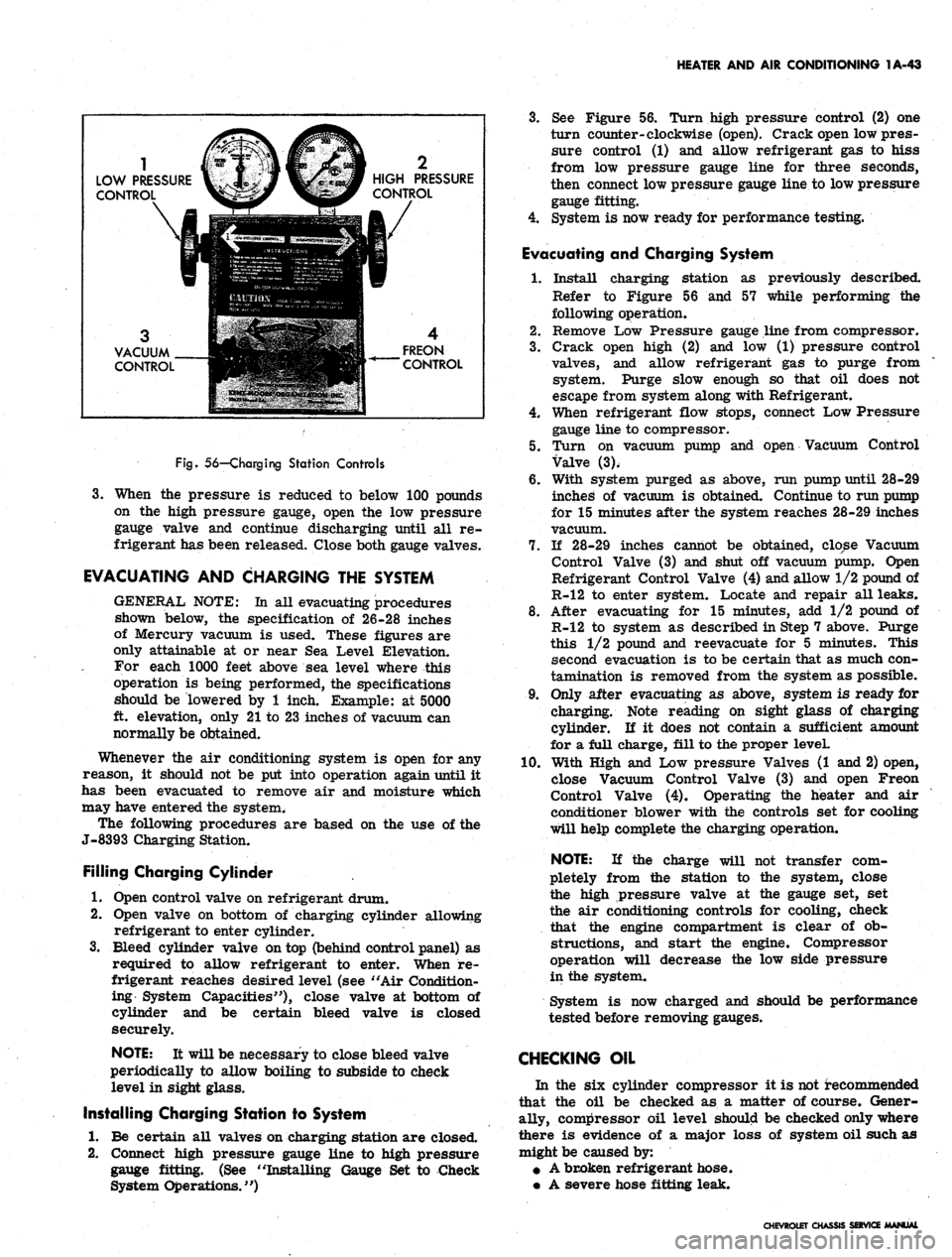
56—Charging Station Controls
3.
When the pressure is reduced to below 100 pounds
on the high pressure gauge, open the low pressure
gauge valve and continue discharging until all re-
frigerant has been released. Close both gauge valves.
EVACUATING AND CHARGING THE SYSTEM
GENERAL NOTE: La all evacuating procedures
shown below, the specification of 26-28 inches
of Mercury vacuum is used. These figures are
only attainable at or near Sea Level Elevation.
For each 1000 feet above sea level where this
operation is being performed, the specifications
should be lowered by 1 inch. Example: at 5000
ft. elevation, only 21 to 23 inches of vacuum can
normally be obtained.
Whenever the air conditioning system is open for any
reason, it should not be put into operation again until it
has been evacuated to remove air and moisture which
may have entered the system.
The following procedures are based on the use of the
J-8393 Charging Station.
Filling Charging Cylinder
1.
Open control valve on refrigerant drum.
2.
Open valve on bottom of charging cylinder allowing
refrigerant to enter cylinder.
3.
Bleed cylinder valve on top (behind control panel) as
required to allow refrigerant to enter. When re-
frigerant reaches desired level (see "Air Condition-
ing System Capacities"), close valve at bottom of
cylinder and be certain bleed valve is closed
securely.
NOTE: It will be necessary to close bleed valve
periodically to allow boiling to subside to check
level in sight glass.
Installing Charging Station to System
1.
Be certain all valves on charging station are closed.
2.
Connect high pressure gauge line to high pressure
gauge fitting. (See "Installing Gauge Set to Check
System Operations.")
3.
See Figure 56. Turn high pressure control (2) one
turn counter-clockwise (open). Crack open low pres-
sure control (1) and allow refrigerant gas to hiss
from low pressure gauge line for three seconds,
then connect low pressure gauge line to low pressure
gauge fitting.
4.
System is now ready for performance testing.
Evacuating and Charging System
1.
Install charging station as previously described.
Refer to Figure 56 and 57 while performing the
following operation.
2.
Remove Low Pressure gauge line from compressor.
3.
Crack open high (2) and low (1) pressure control
valves, and allow refrigerant gas to purge from
system. Purge slow enough so that oil does not
escape from system along with Refrigerant.
4.
When refrigerant flow stops, connect Low Pressure
gauge line to compressor.
5.
Turn on vacuum pump and open Vacuum Control
Valve (3).
6. With system purged as above, run pump until 28-29
inched of vacuum is obtained. Continue to run pump
for 15 minutes after the system reaches 28-29 inches
vacuum.
7.
If 28-29 inches cannot be obtained, close Vacuum
Control Valve (3) and shut off vacuum pump. Open
Refrigerant Control Valve (4) and allow 1/2 pound of
R-12 to enter system. Locate and repair all leaks.
8. After evacuating for 15 minutes, add 1/2 pound of
R-12 to system as described in Step 7 above. Purge
this 1/2 pound and reevacuate for 5 minutes. This
second evacuation is to be certain that as much con-
tamination is removed from the system as possible.
9. Only after evacuating as above, system is ready for
charging. Note reading on sight glass of charging
cylinder. If it does not contain a sufficient amount
for a full charge, fill to the proper leveL
10.
With High and Low pressure Valves (1 and 2) open,
close Vacuum Control Valve (3) and open Freon
Control Valve (4). Operating the heater and air
conditioner blower with the controls set for cooling
will help complete the charging operation.
NOTE: If the charge will not transfer com-
pletely from the station to the system, close
the high pressure valve at the gauge set, set
the air conditioning controls for cooling, check
that the engine compartment is clear of ob-
structions, and start the engine. Compressor
operation will decrease the low side pressure
in the system.
System is now charged and should be performance
tested before removing gauges.
CHECKING OIL
In the six cylinder compressor it is not recommended
that the oil be checked as a matter of course. Gener-
ally, compressor oil level should be checked only where
there is evidence of a major loss of system oil such as
might be caused by:
• A broken refrigerant hose.
• A severe hose fitting leak.
CHEVROLET CHASSIS SERVICE MANUAL
Page 88 of 659
HEATER AND AIR CONDITIONING 1A-65
Fig.
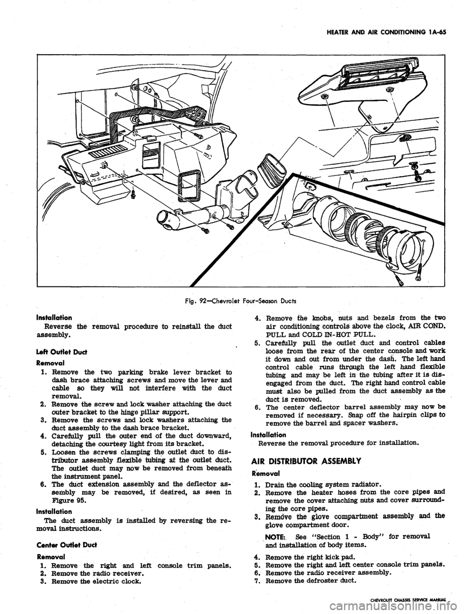
92—Chevrolet Four-Season Ducts
Installation
Reverse
assembly.
the removal procedure to reinstall the duct
Left Outlet Duct
Removal
1.
Remove the two parking brake lever bracket to
dash brace attaching screws and move the lever and
cable so they will not interfere with the duct
removal.
2.
Remove the screw and lock washer attaching the duct
outer bracket to the hinge pillar support.
3.
Remove the screws and lock washers attaching the
duct assembly to the dash brace bracket.
4.
Carefully pull the outer end of the duct downward,
detaching the courtesy light from its bracket.
5. Loosen the screws clamping the outlet duct to dis-
tributor assembly flexible tubing at the outlet duct.
The outlet duct may now be removed from beneath
the instrument panel.
6. The duct extension assembly and the deflector as-
sembly may be removed, if desired, as seen in
Figure 95.
Installation
The duct assembly is installed by reversing the re-
moval instructions.
Center Outlet Duct
Removal
1.
Remove the right and left console trim panels.
2.
Remove the radio receiver.
3.
Remove the electric clock.
4.
Remove the knobs, nuts and bezels from the two
air conditioning controls above the clock, AIR COND.
PULL and COLD IN-HOT PULL.
5. Carefully pull the outlet duct and control cables
loose from the rear of the center console and work
it down and out from under the dash. The left hand
control cable runs through the left hand flexible
tubing and may be left in the tubing after it is dis-
engaged from the duct. The right hand control cable
must also be pulled from the duct assembly as the
duct is removed.
6. The center deflector barrel assembly may now be
removed if necessary. Snap off the hairpin clips to
remove the barrel and spacer washers.
Installation
Reverse the removal procedure for installation.
AIR DISTRIBUTOR ASSEMBLY
Removal
1.
Drain the cooling system radiator.
2.
Remove the heater hoses from the core pipes and
remove the cover attaching nuts and cover surround-
ing the core pipes.
3.
Remove the glove compartment assembly and the
glove compartment door.
NOTE:.
See "Section 1 - Body" for removal
and installation of body items.
4.
Remove the right kick pad.
5. Remove the right and left center console trim panels.
6. Remove the radio receiver assembly.
7. Remove the defroster duct.
CHEVROLET CHASSIS SERVICE MANUAL
Page 118 of 659

CORVETTE BODY 1B-11
CLAYOfc
CAULKING
COMPOUND
Fig. 26-Window Rear Stop - Typical
Fig. 24—Checking Adjustment of Striker
3.
Adjust door as required. Location of hinge retaining
bolts may be seen in Figure 25 at "A". Do not allow
doors to hang on one hinge without support.
4.
Install trim pad and lubricate door "hold opens" and
hinges with Lubriplate or its equivalent.
NOTE:
After performing any door adjustment,
the window and door post should be checked for
alignment and adjusted as necessary. In addi-
tion,
never slam the door after adjustment with-
out first checking the door lock and striker plate
engagement. An adjustment may be necessary.
TRIM PANEL, AND INSIDE HANDLES
Figure 29 is an exploded view of integral arm rest,
inside handles, and trim panel fastenings.
Removal of trim panel may be accomplished as
follows:
1.
Remove two screws under arm rest.
2.
Using Tool J-7797, remove clips retaining window
crank and lock remote control as shown in Figure 28.
3.
Remove knob from door lock control by turning
counter-clockwise.
4.
Remove 2 screws retaining inside pull handle.
5. Remove sheet metal screws and special washers
retaining trim panel to door assembly.
6. Pull trim panel out. at bottom, tap bottom edge of
trim panel with hand to disengage from top of door.
Remove trim panel from vehicle.
WEATHERSTRIP
Figure
30
illustrates both 19437 and 19467 model door
COWL
Fig.
25-Door Adjustment Points
Fig.
27-Door Hinge
CHEVROLET CHASSIS SERVICE MANUAL
Page 138 of 659
CORVETTE BODY 1B-31
1
^JS^ST**-
Fig.
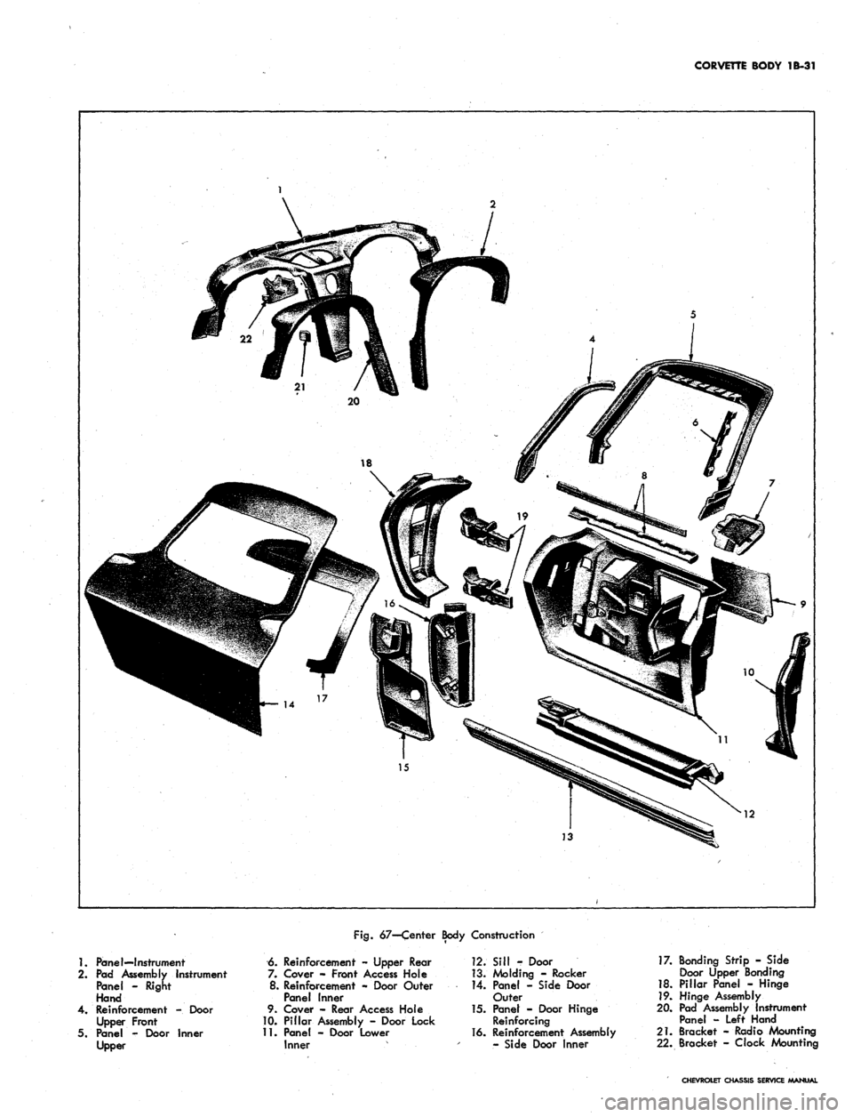
67—Center Body Construction
1.
Panel—Instrument
2.
Pad Assembly Instrument
Panel - Right
Hand
4.
Reinforcement -. Door
Upper Front
5. Panel - Door Inner
Upper
6. Reinforcement - Upper Rear
7. Cover - Front Access Hole
8. Reinforcement - Door Outer
Panel inner
9. Cover - Rear Access Hole
10.
Pillar Assembly - Door Lock
11.
Panel - Door Lower
Inner
12.
Sill - Door
13.
Molding - Rocker
14.
Panel - Side Door
Outer
15.
Panet - Door Hinge
Reinforcing
16.
Reinforcement Assembly
- Side Door Inner
17.
Bonding Strip - Side
Door Upper Bonding
18.
Pillar Panel - Hinge
19.
Hinge Assembly
20.
Pad Assembly Instrument
Panel - Left Hand
21.
Bracket - Radio Mounting
22.
Bracket - Clock Mounting
CHEVROLET CHASSIS SERVICE MANUAL