tow CHEVROLET CAMARO 1967 1.G Chassis Workshop Manual
[x] Cancel search | Manufacturer: CHEVROLET, Model Year: 1967, Model line: CAMARO, Model: CHEVROLET CAMARO 1967 1.GPages: 659, PDF Size: 114.24 MB
Page 3 of 659
SECTION O
INFORMATION AND LUBRICATION
CONTENTS OF THIS SECTION
Page
General Information o-l
Lubrication 0-13
GENERAL INFORMATION
Model Identification and Vehicle Dimensions
Chevrolet
Chevelle
Chevy n
Corvette
Camaro
Page
0-1
0-1
0-2
0-2
0-3
0-3
Page
Unit and Serial Numbers o-3
Engine Number o-3
Vehicle Serial Number 0r3
Keys and Locks 0-4
Pushing,Towing and Lifting 0-7
Series
Biscayne
Bel Air
Tmpala.
Impala
Super Sport
Caprice
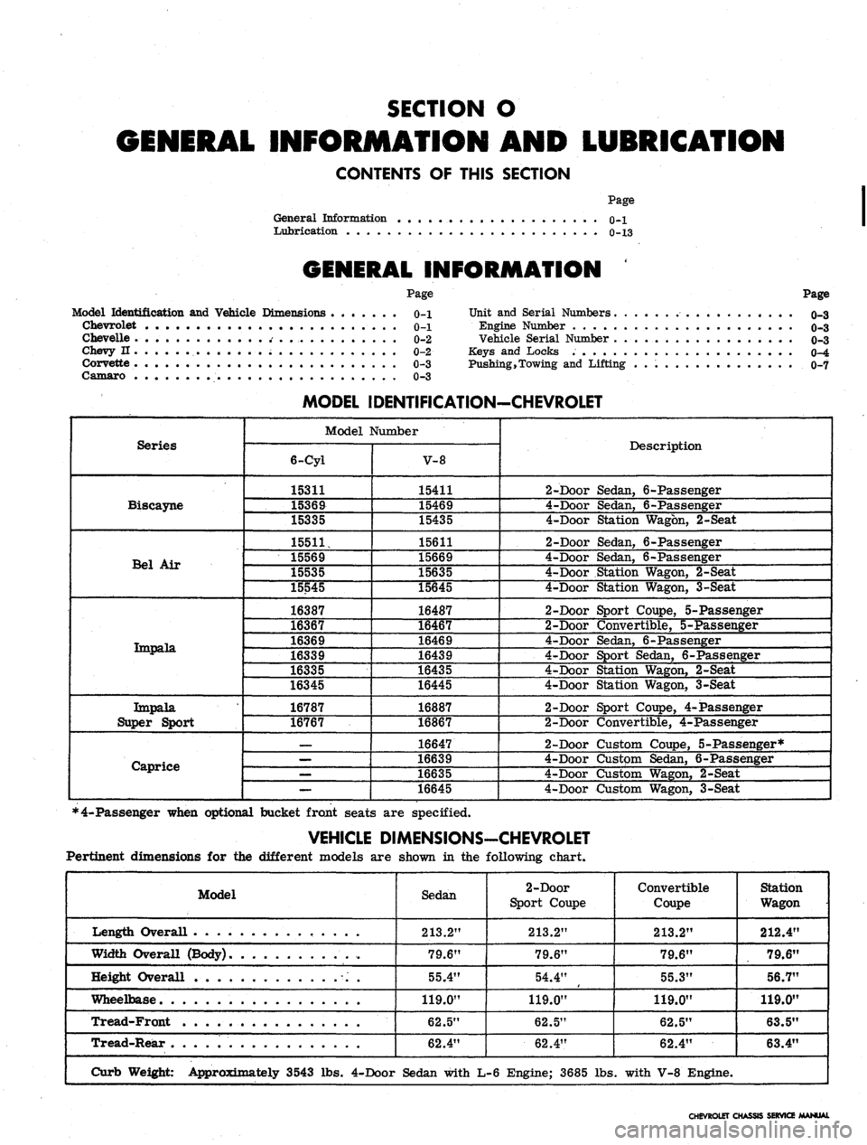
MODEL IDENTIFICATION-CHEVROLET
Model Number
6-Cyl
15311
15369
15335
15511,
15569
15535
15545
16387
16367
16369
16339
16335
16345
16787
16767
—
—
—
—
V-8
15411
15469
15435
15611
15669
15635
15645
16487
16467
16469
16439
16435
16445
16887
16867
16647
16639
16635
16645
Description
2-Door Sedan, 6-Passenger
4-Door Sedan, 6-Passenger
4-Door Station Wagon, 2-Seat
2-Door Sedan, 6-Passenger
4-Door Sedan, 6-Passenger
4-Door Station Wagon, 2-Seat
4-Door Station Wagon, 3-Seat
2-Door Sport Coupe, 5-Passenger
2-Door Convertible, 5-Passenger
4-Door Sedan, 6-Passenger
4-Door Sport Sedan, 6-Passenger
4-Door Station Wagon, 2-Seat
4-Door Station Wagon, 3-Seat
2-Door Sport Coupe, 4-Passenger
2-Door Convertible, 4-Passenger
2-Door Custom Coupe, 5-Passenger*
4-Door Custpm Sedan, 6-Passenger
4-Door Custom Wagon, 2-Seat
4-Door Custom Wagon, 3-Seat
*4-Passenger when optional bucket front seats are specified.
VEHICLE DIMENSIONS-CHEVROLET
Pertinent dimensions for the different models are shown in the following chart.
Model
Length Overall . .
Width Overall (Body)
Height Overall
Wheelbase
Tread-Front
Tread-Rear
Curb Weight: Approximately 3543 lbs.
Sedan
213.2"
79.6"
55.4"
119.0"
62.5"
62.4"
4-Door Sedan with
2-Door
Sport Coupe
213.2"
79.6"
54.4"
119.0"
62.5"
62.4"
L-6 Engine; 3685 lbs
Convertible
Coupe
213.2"
79.6"
55.3"
119.0"
62.5"
62.4"
. with V-8 Engine.
Station
Wagon
212.4"
79.6"
56.7"
119.0"
63.5"
63.4"
CHEVROLET CHASSIS SERVICE MANUAL
Page 7 of 659
GENERAL INFORMATION 0-5
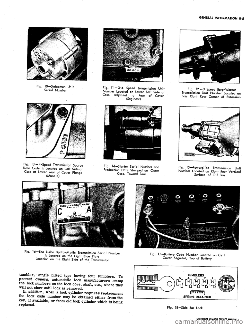
Fig.
10—Delcotron Unit
Serial Number
Fig.
11—3-4 Speed Transmission Unit
Number Located on Lower Left Side of
Case Adjacent to Rear of Cover
(Saginaw)
Fig.
12-3 Speed Borg-Warner
Transmission Unit Number Located on
Boss Right Rear Comer of Extension
Fig.
13 — 4-Speed Transmission Source
Data Code is Located on Left Side of
Case at Lower Rear of Cover Flange
(Muncie)
Fig.
14—Starter Serial Number and
Production Date Stamped on Outer
Case,
Toward Rear
Fig.
15—Powerglide Transmission Unit
Number located on Right Rear Vertical
Surface of Oil Pan
16—The Turbo Hydra-Matic Transmission Serial Number
is Located on the Light Blue Plate
Location on the Right Side of the Transmission
tumbler, single bitted type having four tumblers. To
protect owners, automobile lock manufacturers stamp
the lock numbers on the lock core, shaft, etc., where they
will not show until lock is removed.
In addition, when a lock cylinder requires replacement
the lock code number may be obtained either from the
key, if available, or from old lock cylinder which is being
replaced.
Fig.
17—Battery Code Number Located on Cell
Cover Segment, Top of Battery
TUMBLERS
5 4 3 2 1
jjwvvvvvjl
SPRING RETAINER
Fig.
18-Side Bar Lock
CHEVROLET CHASSIS SERVICE MANUAL
Page 8 of 659
GENERAL INFORMATION
0-6
Once the code number of the lock is obtained look up
this number in a key cutting book.
All side bar locks (except trunk) furnished to the field
by the Parts' Department are uncoded, that is, they are
furnished without tumblers, springs or spring retainers,
these parts are serviced separately. The tumblers come
in five different depths, indicated by numbers.
The side bar locks have six tumbler positions, and in
looking up the cutting code, the following may be used as
an example. After key code number is determined, either
from key or from number stamped on lock cylinder refer
to your code book and record the key cutting information
as follows:
Key of Lock
Code Number
0V11
Cutting or Tumbler
position from head
of lock
Key Cutting
Code Numerical
545431
123456
NOTE:
Key blanks used for ignition and door
locks are stamped with an "A" while rear com-
partment and glove box blanks are stamped with
a "B".
The number that is written above the cutting or tumbler
position indicates each different tumbler which is to be
dropped into each tumbier slot of the lock.
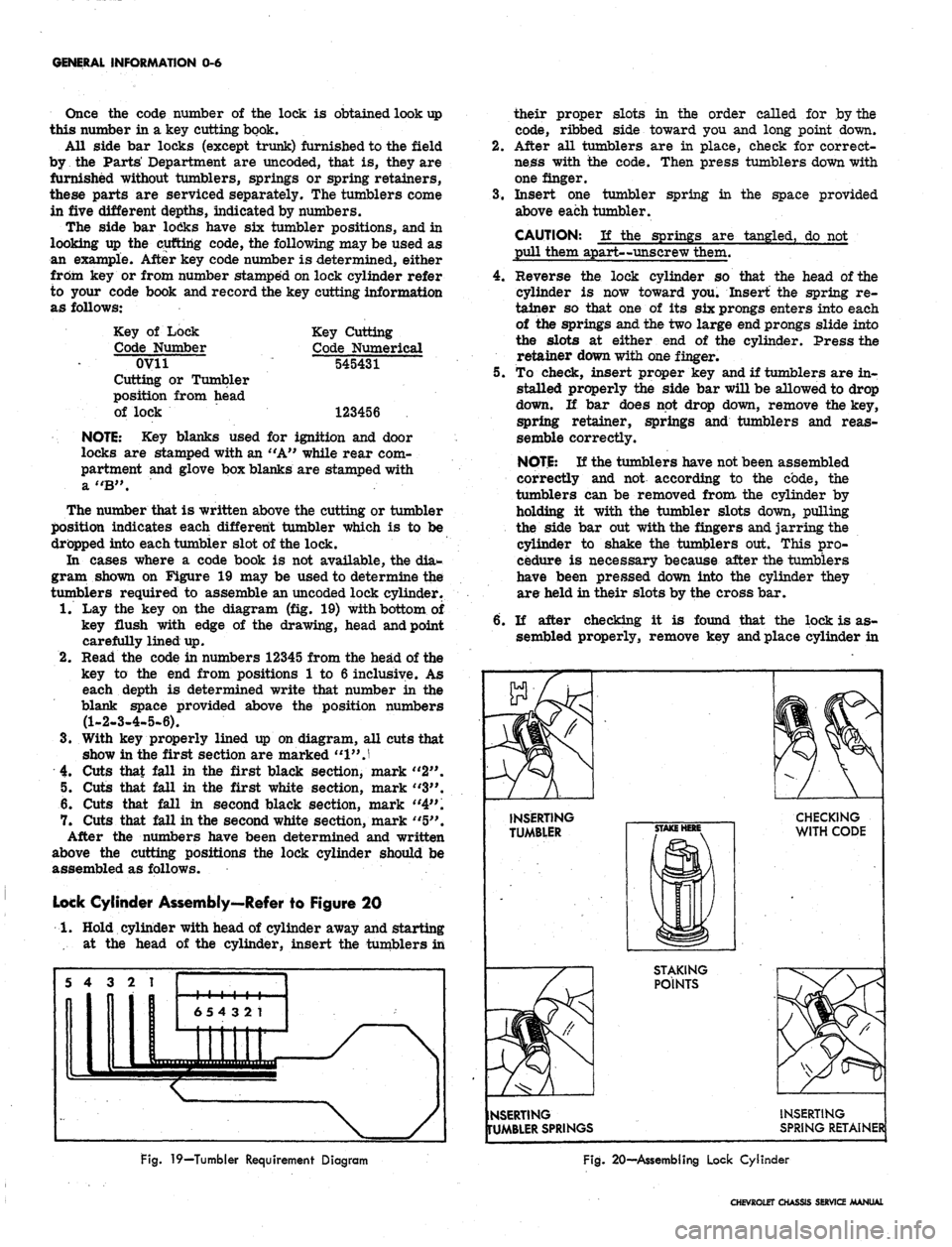
In cases where a code book is not available, the dia-
gram shown on Figure 19 may be used to determine the
tumblers required to assemble an uncoded lock cylinder.
1.
Lay the key on the diagram (fig. 19) with bottom of
key flush with edge of the drawing, head and point
carefully lined up.
2.
Read the code in numbers 12345 from the head of the
key to the end from positions 1 to 6 inclusive. As
each depth is determined write that number in the
blank space provided above the position numbers
(1-2-3-4-5-6).
3.
With key properly lined up on diagram, all cuts that
show in the first section are marked
"1"
J
4.
Cuts that fall in the first black section, mark "2".
5. Cuts that fall in the first white section, mark "3".
6. Cuts that fall in second black section, mark "4".
7. Cuts that fall in the second white section, mark "5".
After the numbers have been determined and written
above the cutting positions the lock cylinder should be
assembled as follows.
Lock Cylinder Assembly—Refer to Figure 20
1.
Hold cylinder with head of cylinder away and starting
•... at the head of the cylinder, insert the tumblers in
their proper slots in the order called for by the
code, ribbed side toward you and long point down.
2.
After all tumblers are in place, check for correct-
ness with the code. Then press tumblers down with
one finger.
3.
Insert one tumbler spring in the space provided
above each tumbler.
CAUTION: If the springs are tangled, do not
pull them apart—unscrew them.
4.
Reverse the lock cylinder so that the head of the
cylinder is now toward you. Insert the spring re-
tainer so that one of its six prongs enters into each
of the springs and the two large end prongs slide into
the slots at either end of the cylinder. Press the
retainer down with one finger.
5. To check, insert proper key and if tumblers are in-
stalled properly the side bar will be allowed to drop
down. If bar does not drop down, remove the key,
spring retainer, springs and tumblers and reas-
semble correctly.
NOTE:
If the tumblers have not been assembled
correctly and not according to the code, the
tumblers can be removed from the cylinder by
holding it with the tumbler slots down, pulling
the side bar out with the fingers and jarring the
cylinder to shake the tumblers out. This pro-
cedure is necessary because after the tumblers
have been pressed down into the cylinder they
are held in their slots by the cross bar.
6. If after checking it is found that the lock is as-
sembled properly, remove key and place cylinder in
INSERTING
TUMBLER
CHECKING
WITH CODE
STAKING
POINTS
NSERTING
TUMBLER SPRINGS
INSERTING
SPRING RETAINER
Fig.
19—Tumbler Requirement Diagram
Fig.
20—Assembling Lock Cylinder
CHEVROLET CHASSIS SERVICE MANUAL
Page 9 of 659
GENERAL INFORMATION 0-7
a vise using leather or wood on each side to prevent
damage to the cylinder,
7. Stake the retainer securely in place by staking the
cylinder metal over both edges of the retainer ends
using a suitable staking tool at right angles to the
top of the retainer and from the cast metal of the
cylinder over the retainer at each corner.
PUSHING, TOWING AND LIFTING
Pushing
NOTE:
Towing car to start is not recommended
due to the possibility of the disabled car ac-
celerating into tow car.
AUTOMATIC TRANSMISSION
Do not attempt to start the engine by pushing the car.
Should the battery become discharged, it will be neces-
sary to use an auxiliary battery with jumper cables to
start the engine.
CAUTION: To prevent damage to electrical
system, never connect booster batteries in ex-
cess of 12 volts and connect positive to positive
and negative to negative.
Manual Transmission
When a push start is necessary turn off all electrical
loads such as heater, radio, and if possible, lights, turn
on the key, depress the clutch, and place the shift lever
in high gear. Release the clutch when your speed reaches
10 to 15 miles per hour.
TOWING
The car may be towed safely on its rear wheels with
the (selector lever in "N" (Neutral) position at speeds
of 35 miles per hour or less under most conditions.
However, the drive shaft must be disconnected or the
car towed on its front wheels if 1) Tow speeds in excess
of 35 MPH are necessary, 2) Car must be towed for ex-
tended distances (over 50 miles) or, 3) Transmission is
not operating properly. If car is towed on its front
wheels, the steering wheel should be secured to maintain
a straight ahead position.
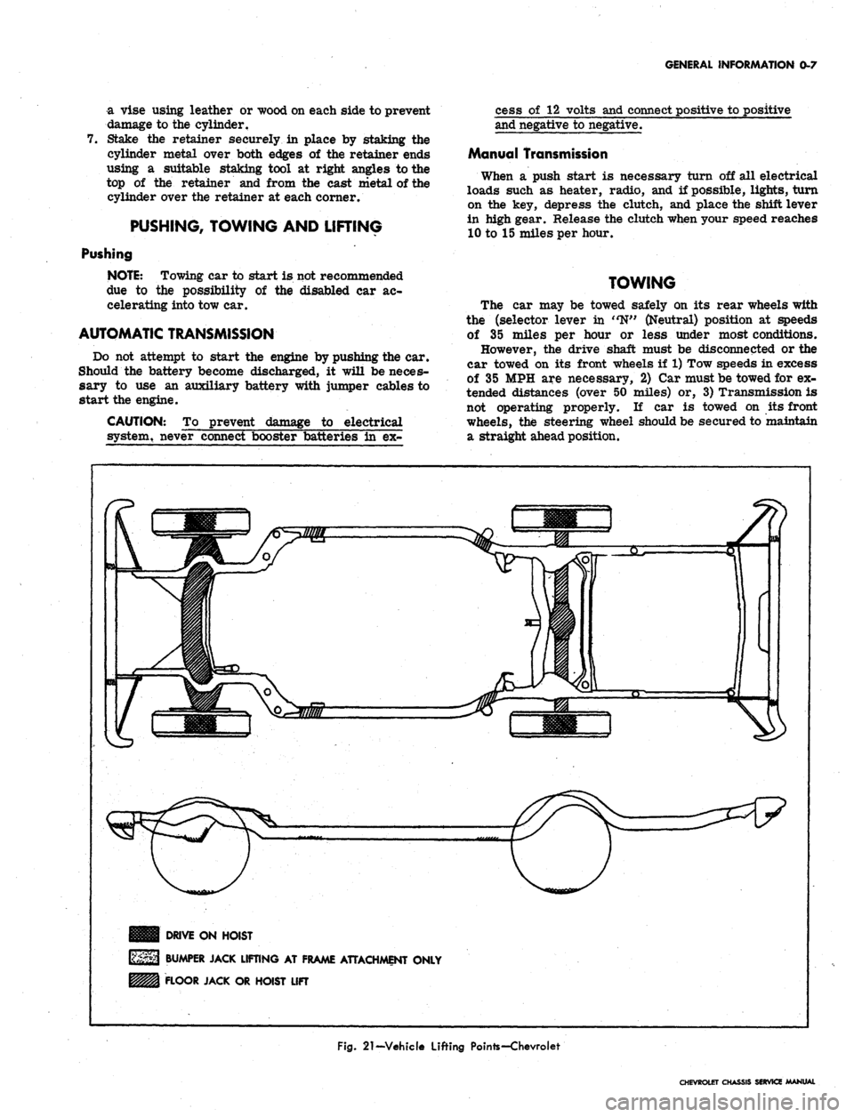
DRIVE ON HOIST
BUMPER JACK LIFTING AT FRAME ATTACHMENT ONLY
FLOOR JACK OR HOIST LIFT
Fig.
21-Vehicle Lifting Pointe-Chevroiet
CHEVROLET CHASSIS SERVICE MANUAL
Page 10 of 659
GENERAL INFORMATION 0-8
nun
Illllfl Q
i,,,,,,,,
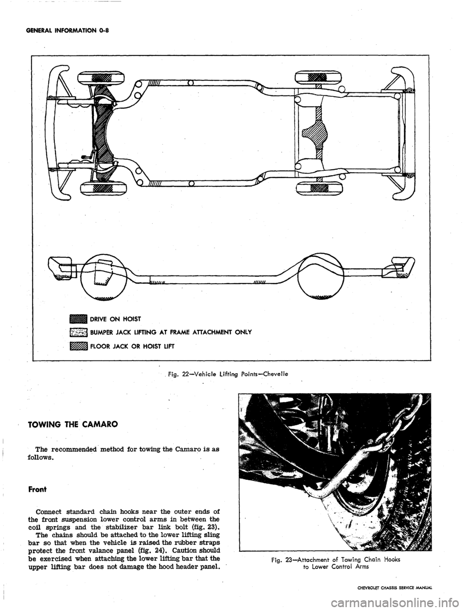
DRIVE ON HOIST
BUMPER JACK LIFTING AT FRAME ATTACHMENT ONLY
FLOOR JACK OR HOIST LIFT
Fig.
22—Vehicle Lifting Points—Chevelle
TOWING THE CAMARO
The recommended method for towing the Camaro is
follows.
Front
Connect standard chain hooks near the outer ends of
the front suspension lower control arms in between the
coil springs and the stabilizer bar link bolt (fig. 23).
The chains should be attached to the lower lifting sling
bar so that when the vehicle is raised the rubber straps
protect the front valance panel (fig. 24). Caution should
be exercised when attaching the lower lifting bar that the
upper lifting bar does not damage the hood header panel.
Fig. 23—Attachment of Towing Chain Hooks
to Lower Control Arms
CHEVROLET CHASSIS SERVICE MANUAL
Page 11 of 659
GENERAL INFORMATION
0-9
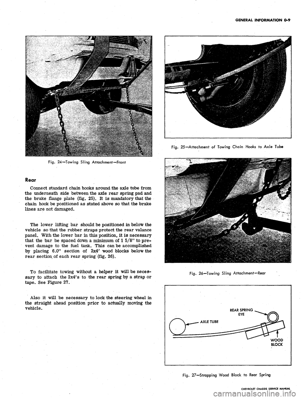
Fig.
25—Attachment
of
Towing Chain Hooks
to
Axle Tube
Fig.
24—Towing Sling Attachment—Front
Rear
Connect standard chain hooks around the axle tube from
the underneath side between the axle rear spring pad and
the brake flange plate (fig. 25). It is mandatory that the
chain hook be positioned as stated above so that the brake
lines are not damaged.
The lower lifting bar should be positioned in below the
vehicle so that the rubber straps protect the rear valance
panel. With the lower bar in this position, it is necessary
that the bar be spaced down a minimum of
1
5/8" to pre-
vent damage to the fuel tank. This can be accomplished
by placing 6.0" section of 2x4' wood blocks below the
rear section of each rear spring (fig. 26).
To facilitate towing without a helper it will be neces-
sary to attach the
2x4*
s to the rear spring by a strap or
tape.
See Figure 27.
Also it will be necessary to lock the steering wheel in
the straight ahead position prior to actually moving the
vehicle.
Fig.
26—Towing SJing Attachment—Rear
REAR SPRING
EYE
WOOD
BLOCK
Fig.
27—Strapping Wood Block
to
Rear Spring
CHEVROLET CHASSIS SERVICE MANUAL
Page 25 of 659
HEATER AND AIR CONDITIONING 1A-2
DEFROSTER-q
DOOR
v-
HEATER
OUTLET
DEFROSTER
OUTSIDE
AIR
FROM PLENUM
OUTLETS
""•—
,
BLOWER
« 1
/ y
r J
\
AIR
DUQ
•*-——
DOOR
—-**
X J
HEAT
DOOR
HEATER
CORE
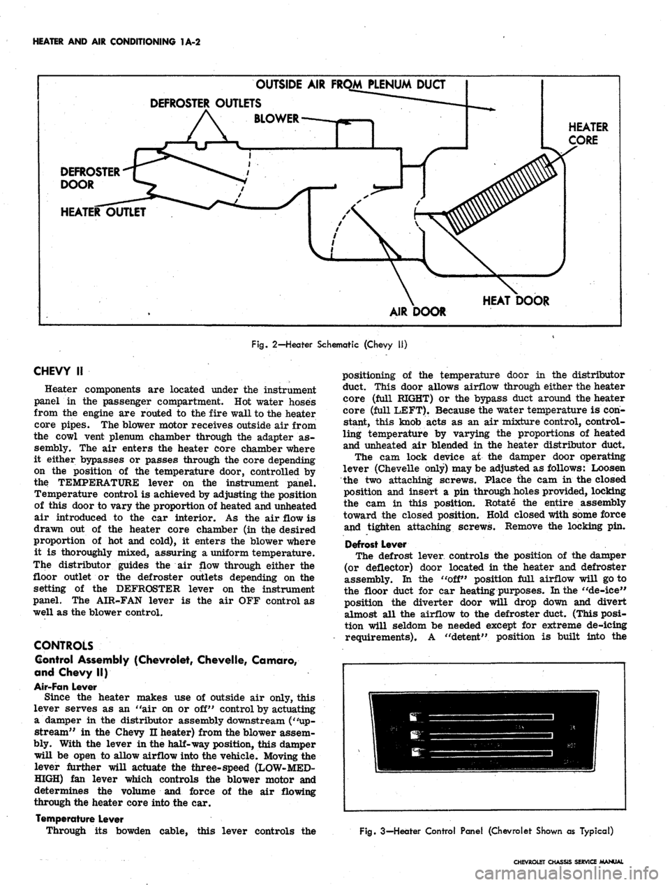
Fig. 2-Heater Schematic (Chevy 11)
CHEVY
II
Heater components are located under the instrument
panel in the passenger compartment. Hot water hoses
from the engine are routed to the fire wall to the heater
core pipes. The blower motor receives outside air from
the cowl vent plenum chamber through the adapter as-
sembly. The air enters the heater core chamber where
it either bypasses or passes through the core depending
on the position of the temperature door, controlled by
the TEMPERATURE lever on the instrument panel.
Temperature control is achieved by adjusting the position
of this door to vary the proportion of heated and unheated
air introduced to the car interior. As the air flow is
drawn out of the heater core chamber (in the desired
proportion of hot and cold), it enters the blower where
it is thoroughly mixed, assuring a uniform temperature.
The distributor guides the air flow through either the
floor outlet or the defroster outlets depending on the
setting of the DEFROSTER lever on the instrument
panel. The AIR-FAN lever is the air OFF control as
well as the blower control.
CONTROLS
Control Assembly (Chevrolet, Chevelle, Camaro,
and Chevy II)
Air-Fan Lever
Since the heater makes use of outside air only, this
lever serves as an "air on or off" control by actuating
a damper in the distributor assembly downstream ("up-
stream" in the Chevy n heater) from the blower assem-
bly. With the lever in the half-way position, this damper
will be open to allow airflow into the vehicle. Moving the
lever further will actuate the three-speed (LOW-MED-
HIGH) fan lever which controls the blower motor and
determines the volume and force of the air flowing
through the heater core into the car.
Temperature Lever
Through its bowden cable, this lever controls the
positioning of the temperature door in the distributor
duct. This door allows airflow through either the heater
core (full RIGHT) or the bypass duct around the heater
core (full LEFT). Because the water temperature is con-
stant, this knob acts as an air mixture control, control-
ling temperature by varying the proportions of heated
and unheated air blended in the heater distributor duct.
The cam lock device at the damper door operating
lever (Chevelle only) may be adjusted as follows: Loosen
the two attaching screws. Place the cam in the closed
position and insert a pin through holes provided, locking
the cam in this position. Rotate the entire assembly
toward the closed position. Hold closed with some force
and tighten attaching screws. Remove the locking pin.
Defrost Lever
The defrost lever controls the position of the damper
(or deflector) door located in the heater and defroster
assembly. In the "off" position full airflow will go to
the floor duct for car heating purposes. In the "de-ice"
position the diverter door will drop down and divert
almost all the airflow to the defroster duct. (This posi-
tion will seldom be needed except for extreme de-icing
requirements). A "detent" position is built into the
Fig. 3—Heater Control Panel (Chevrolet Shown as Typical)
CHEVROLET CHASSIS SERVICE MANUAL
Page 28 of 659
HEATER AND AIR CONDITIONING 1A-5
them in their proper location. (See Figure 8)
12.
Refill radiator.
Defroster Duct
Figure 9 illustrates the defroster duct installation
on Chevrolet, Chevelle and Camaro vehicles.
Bowden Cobles
Bowden cable attachment should be made in the fol-
lowing manner:
1.
With the cables attached to the control assembly
and levers, move the levers to their fully left or
closed position.
2.
Attach cable wires to the heater valve levers and
tighten cable attaching bracket screws.
3.
Check for proper cable operation and readjust as
necessary.
Control Panel
Control panel installation is shown in Figures 10, 11,
and 12.
Fan Switch
Replacement
1.
Remove control assembly-to-instrument panel re-
inforcement attaching screws and push the control
assembly toward the front of the vehicle and down.
2.
Remove the two switch attaching screws and the
electrical connector.
3.
Replace switch, screws, and electrical connector.
4.
Place control assembly into instrument panel and
replace attaching screws.
Resistor
The resistor assembly is attached to the heater dis-
tributor assembly. It should "be replaced if low or
medium blower speed is inoperative. Remove the glove
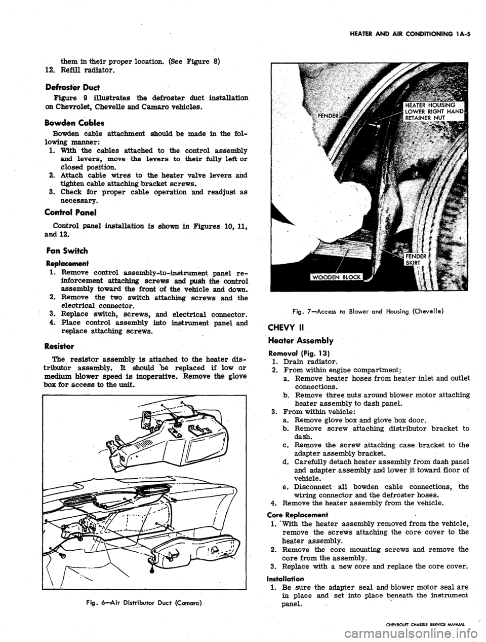
box for access to the unit.
HEATER HOUSING
LOWER RIGHT HAND
RETAINER NUT
Fig.
6—Air Distributor Duct (Camaro)
Fig.
7—Access to Blower and Housing (Chevelle)
CHEVY II
Heater Assembly
Removal (Fig. 13)
1.
Drain radiator.
2.
From within engine compartment;
a. Remove heater hoses from heater inlet and outlet
connections.
b.
Remove three nuts around blower motor attaching
heater assembly to dash panel.
3.
From within vehicle:
a. Remove glove box and glove box door.
b.
Remove screw attaching distributor bracket to
dash.
c. Remove the screw attaching case bracket to the
adapter assembly bracket.
d. Carefully detach heater assembly from dash panel
and adapter assembly and lower it toward floor of
vehicle.
e. Disconnect all bowden cable connections, the
wiring connector and the defroster hoses.
4.
Remove the heater assembly from the vehicle.
Core Replacement
1.
'With the heater assembly removed from the vehicle,
remove the screws attaching the core cover to the
heater assembly.
2.
Remove the core mounting screws and remove the
core from the assembly.
3.
Replace with a new core and replace the core cover.
Installation
1.
Be sure the adapter seal and blower motor seal are
in place and set into place beneath the instrument
panel.
CHEVROLET CHASSIS SERVICE MANUAL
Page 55 of 659
HEATER AND AIR CONDITIONING 1A-32
5.
Check hose clamp connections. If clamp screw torque
is less than 10 lb. in., retighten to 20-25 lb. in. Do
not tighten to new hose specifications or hose leak-
age may occur.
6. If there is evidence of an oil leak, check the com-
pressor to see that the oil charge is satisfactory.
7.
Check the system controls for proper operation.
6000 MILE INSPECTION
1.
Check unit for any indication of a refrigerant leak.
2.
If there is an indication of an oil leak, check the
compressor proper oil charge.
3.
Check sight glass for proper charge of Refrigerant-
12.
4.
Tighten the compressor brace and support bolts and
check the belt tension.
5.
Check hose clamp connections as in step 5 above.
6. Check thermostatic switch setting (Universal and
All-Weather Systems.)
PERIODIC SERVICE
• Inspect condenser regularly to be sure that it is not
plugged with leaves or other foreign material.
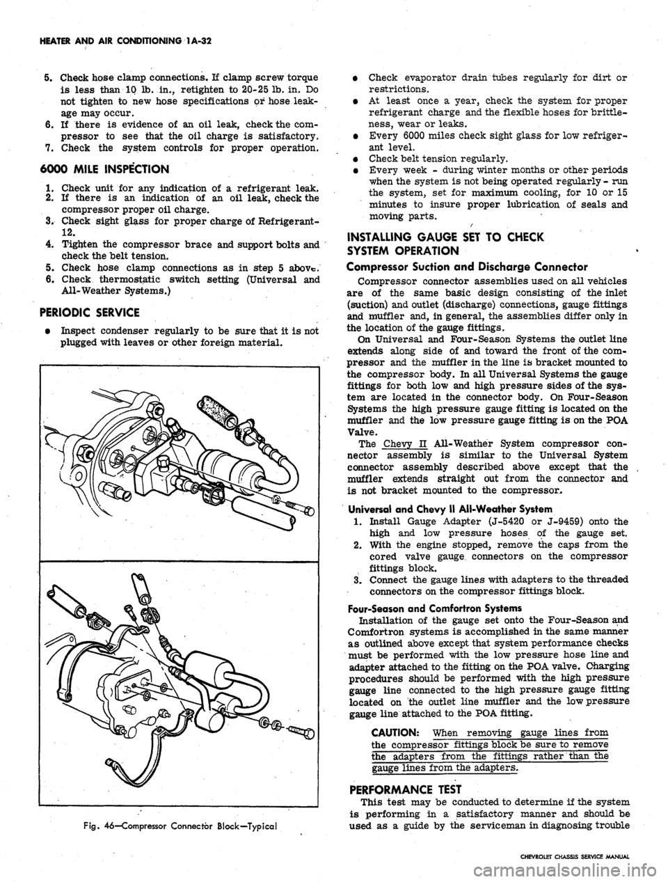
Fig.
46—Compressor Connector Block—Typical
• Check evaporator drain tubes regularly for dirt or
restrictions.
• At least once a year, check the system for proper
refrigerant charge and the flexible hoses for brittle-
ness,
wear or leaks.
• Every 6000 miles check sight glass for low refriger-
ant level.
• Check belt tension regularly.
• Every week - during winter months or other periods
when the system is not being operated regularly- run
the system, set for maximum cooling, for 10 or 15
minutes to insure proper lubrication of seals and
moving parts.
INSTALLING GAUGE SET TO CHECK
SYSTEM OPERATION
Compressor Suction and Discharge Connector
Compressor connector assemblies used on all vehicles
are of the same basic design consisting of the inlet
(suction) and outlet (discharge) connections, gauge fittings
and muffler and, in general, the assemblies differ only in
the location of the gauge fittings.
On Universal and Four-Season Systems the outlet line
extends along side of and toward the front of the com-
pressor and the muffler in the line is bracket mounted to
the compressor body. In all Universal Systems the gauge
fittings for both low and high pressure sides of the sys-
tem are located in the connector body. On Four-Season
Systems the high pressure gauge fitting is located on the
muffler and the low pressure gauge fitting is on the POA
Valve.
The Chevy n All-Weather System compressor con-
nector assembly is similar to the Universal System
connector assembly described above except that the
muffler extends straight out from the connector and
is not bracket mounted to the compressor.
Universal and Chevy II All-Weather System
1.
Install Gauge Adapter (J-5420 or J-9459) onto the
high and low pressure hoses of the gauge set.
2.
With the engine stopped, remove the caps from the
cored valve gauge, connectors on the compressor
fittings block.
3.
Connect the gauge lines with adapters to the threaded
connectors on the compressor fittings block.
Four-Season and Comfortron Systems
Installation of the gauge set onto the Four-Season and
Comfortron systems is accomplished in the same manner
as outlined above except that system performance checks
must be performed with the low pressure hose line and
adapter attached to the fitting on the POA valve. Charging
procedures should be performed with the high pressure
gauge line connected to the high pressure gauge fitting
located on the outlet line muffler and the low pressure
gauge line attached to the POA fitting.
CAUTION: When removing gauge lines from
the compressor fittings block be sure to remove
the adapters from the fittings rather than the
gauge lines from the adapters.
PERFORMANCE TEST
This test may be conducted to determine if the system
is performing in a satisfactory manner and should be
used as a guide by the serviceman in diagnosing trouble
CHEVROLET CHASSIS SERVICE MANUAL
Page 76 of 659
HEATER AND AIR CONDITIONING 1A-53
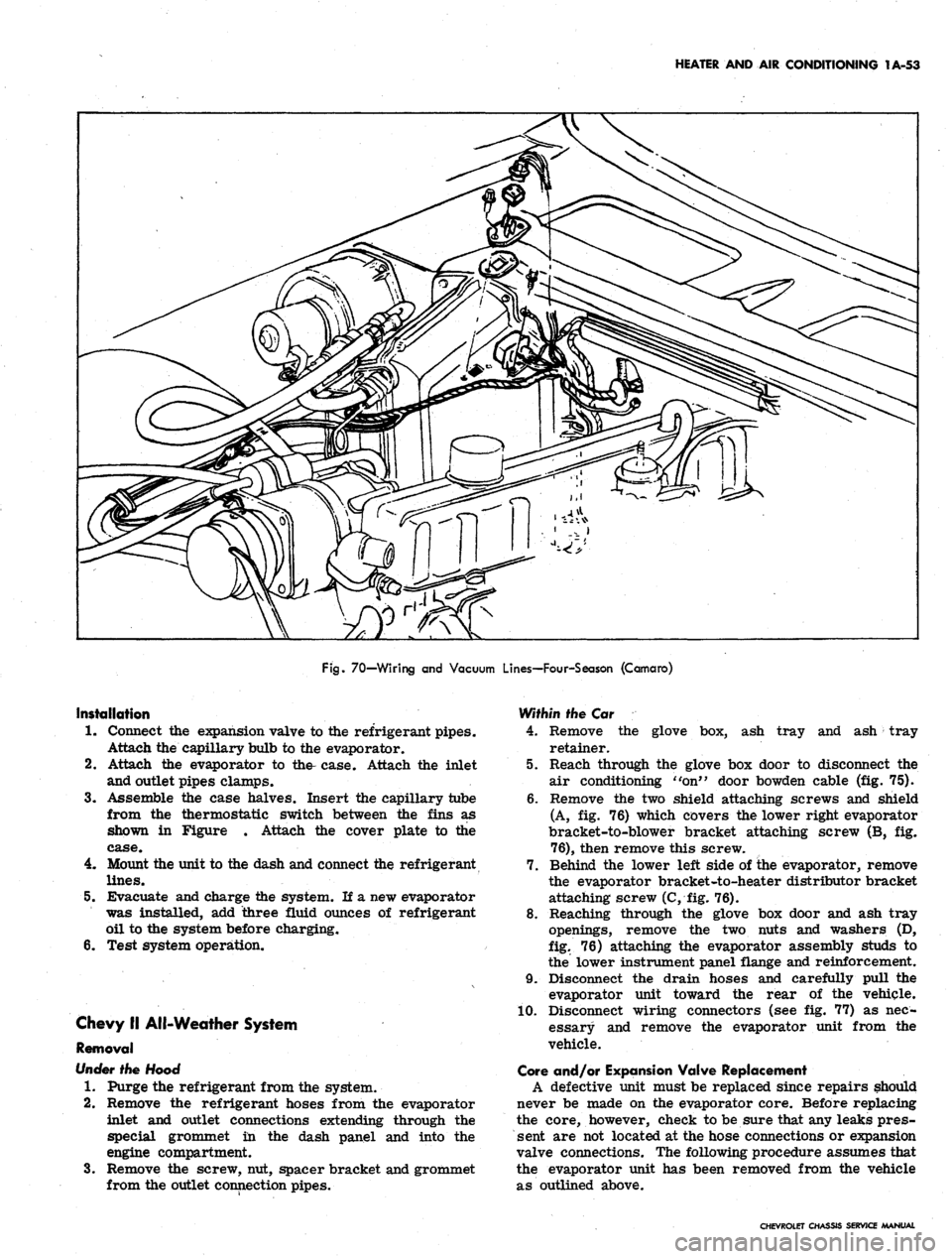
Fig.
70—Wiring and Vacuum Lines—Four-Season (Camaro)
Installation
1.
Connect the expansion valve to the refrigerant pipes.
Attach the capillary bulb to the evaporator.
2.
Attach the evaporator to the- case. Attach the inlet
and outlet pipes clamps.
3.
Assemble the case halves. Insert the capillary tube
from the thermostatic switch between the fins as
shown in Figure . Attach the cover plate to the
case.
4.
Mount the unit to the dash and connect the refrigerant
lines.
5.
Evacuate and charge the system. If a new evaporator
was installed, add three fluid ounces of refrigerant
oil to the system before charging.
6. Test system operation.
Chevy II All-Weather System
Removal
Under
the Hood
1.
Purge the refrigerant from the system.
2.
Remove the refrigerant hoses from the evaporator
inlet and outlet connections extending through the
special grommet in the dash panel and into the
engine compartment.
3.
Remove the screw, nut, spacer bracket and grommet
from the outlet connection pipes.
Within the Car
4.
Remove the glove box, ash tray and ash tray
retainer.
5.
Reach through the glove box door to disconnect the
air conditioning "on" door bowden cable (fig. 75).
6. Remove the two shield attaching screws and shield
(A, fig. 76) which covers the lower right evaporator
bracket-to-blower bracket attaching screw (B, fig.
76),
then remove this screw.
7.
Behind the lower left side of ihe evaporator, remove
the evaporator bracket-to-heater distributor bracket
attaching screw (C, fig. 76).
8. Reaching through the glove box door and ash tray
openings, remove the two nuts and washers (D,
fig.
76) attaching the evaporator assembly studs to
the lower instrument panel flange and reinforcement.
9. Disconnect the drain hoses and carefully pull the
evaporator unit toward the rear of the vehicle.
10.
Disconnect wiring connectors (see fig. 77) as nec-
essary and remove the evaporator unit from the
vehicle.
Gore and/or Expansion Valve Replacement
A defective unit must be replaced since repairs should
never be made on the evaporator core. Before replacing
the core, however, check to be sure that any leaks pres-
sent are not located at the hose connections or expansion
valve connections. The following procedure assumes that
the evaporator unit has been removed from the vehicle
as outlined above.
CHEVROLET CHASSIS SERVICE MANUAL