window CHEVROLET CAMARO 1967 1.G Chassis Workshop Manual
[x] Cancel search | Manufacturer: CHEVROLET, Model Year: 1967, Model line: CAMARO, Model: CHEVROLET CAMARO 1967 1.GPages: 659, PDF Size: 114.24 MB
Page 23 of 659
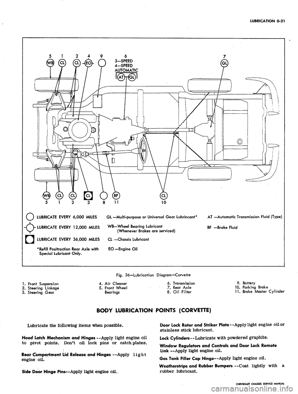
LUBRICATION
0-21
6
3-SPEED
4-SPEED
AUTOMATIC
10
LUBRICATE EVERY 6,000 MILES GL -Multi-purpose
or
Universal Gear Lubrincant*
-(V LUBRICATE EVERY 12,000 MILES WB-Wheel Bearing Lubricant
V/^ (Whenever Brakes
are
serviced)
AT —Automatic Transmission Fluid (Type)
BF -Brake Fluid
a
LUBRICATE EVERY 36,000 MILES
* Refill Positraction Rear Axle with
Special Lubricant Only.
CL -Chassis Lubricant
EO—Engine
Oil
Fig.
36—Lubrication Diagram—Corvette
1.
Front Suspension
2.
Steering Linkage
3. Steering Gear
4.
Air
Cleaner
5. Front Wheel
Bearings
6. Transmission
7. Rear Axle
8.
Oil
Filter
9. Battery
10.
Parking Brake
11.
Brake Master Cylinder
BODY LUBRICATION POINTS (CORVETTE)
Lubricate the following items when possible.
Hood Latch Mechanism and Hinges --Apply light engine oil
to pivot points. Don't oil lock pins or catch plates.
i
Rear Compartment Lid Release and Hinges --Apply light
engine
oil.
Side Door Hinge Pins—Apply light engine oil.
Door Lock Rotor and Striker Plate—Apply light engine oil or
stainless stick lubricant.
Lock Cylinders—Lubricate with powdered graphite.
Window Regulators and Controls and Door Lock Remote
Link —Apply light engine
oil.
Gas Tank Filler Cap Hinge—Apply light engine oil.
Weatherstrips and Rubber Bumpers —Coat lightly with
a
rubber lubricant.
CHEVROLET CHASSIS SERVICE MANUAL
Page 49 of 659
HEATER AND AIR CONDITIONING 1A-26
clockwise for medium and high blower speed, as
desired. Low blower speed is automatic during
cooling operations.
4.
"Def-Pull". This knob should be pushed fully in.
Additional Cooling Hints
1.
The center barrel outlet in the dash may be rotated
to deflect air as desired or used to act as a shut off
door.
2.
The right and left ball outlets may be rotated to
deflect air in the direction desired. Each outlet has
a shut off valve operated by a knob approximately
4 in. inboard. When the knob is horizontal, the valve
is open.
3.
There are two (2) additional outlets in the bottom of
the ducts approximately 6" inboard from the valve
knobs. A rotating cover will open these outlets to
provide cool air for the feet if desired.
4.
When first entering a very warm car, open the
windows for a few minutes until the interior of the
car has cooled off.
Heating
1.
"Air Pull-Fan". Pull this knob fully out. Rotate
the knob clockwise for low, medium or high blower
speed as desired. If just a small amount of heat is
desired, leave the fan on low or medium speed and
regulate the temperature with the "Cool In-Hot Pull"
knob.
2.
"Air Cond-Pull". This knob should normally be
pushed fully in. However, during cool, damp days
it is possible, by pulling this knob fully out, to de-
humidify the air by passing it through the evaporator
core before reheating to the desired outlet
temperature.
3.
"Cool In-Hot Pull". Pull this knob out as far as
necessary to provide the temperature desired.
4.
"Def-Pull". Pull this knob all the way out for
maximum defrosting or de-icing. When the knob is
partly out, a portion of the hot air is used for de-
frosting and the balance is discharged through the
heater outlet.
GENERAL INFORMATION
In any vocation or trade, there are established proce-
dures and practices that have been developed after many
years of experience. In addition, occupational hazards
may be present that require the observation of certain
precautions or use of special tools and equipment. Ob-
serving the procedures, practices and precautions of
servicing refrigeration equipment will greatly reduce the
possibilities of damage to the customers' equipment as
well as virtually eliminate the element of hazard to the
serviceman.
PRECAUTIONS IN HANDLING REFRIGERANT-12
Refrigerant-12 is transparent and colorless in both the
gaseous and liquid state. It has a boiling point of 21.7^
below zero and, therefore, at all normal temperatures
and pressures it will be a vapor. The vapor is heavier
than air and is noninflammable, nonexplosive, non-
poisonous (except when in contact with an open flame)
and noncorrosive (except when in contact with water).
The following precautions in handling R-12 should be
observed at all times.
• All refrigerant drums are shipped with a heavy metal
screw cap. The purpose of the cap is to protect the
valve and safety plug from damage. It is good .prac-
tice to replace the cap after each use of the drum.
• If it is ever necessary to transport or carry a drum
or can of refrigerant in a car, keep it in the luggage
compartment. Refrigerant should not be exposed to
the radiant heat from the sun for the resulting in-
crease in pressure may cause the safety plug to
release or the drum or can to burst..
• Drums or disposable cans should never be subjected
to high temperature when adding refrigerant to the
system. In most instances, heating the drum or can
is required to raise the pressure in the container
higher than the pressure in the system during the
operation. It would be unwise to place the drum on a
gas stove, radiator or use a blow torch while pre-
paring for the charging operation, for a serious ac-
cident can result. Don't depend on the safety
plug - many drums have burst when the safety plug
failed.' Remember, high pressure means that great
forces are being exerted against the walls of the
container. A bucket of warm water, not over 125°F,
or warm wet rags around the container is all the heat
that is required.
• Do not weld or steam clean on or near the system.
Welding or steam cleaning can result in a dangerous
pressure buildup in the system.
• When filling a small drum from a large one, never
fill the drum completely. Space should always be
allowed above the liquid for expansion. If the drum
were completely full and the temperature was in-
creased, hydraulic pressure with its tremendous
force would result.
• Discharging large quantities of R-12 into a room can
usually be done safely as the vapor would produce
no ill effects, however, in the event of an accidental
rapid discharge of the system it is recommended
that inhalation of large quantities of R-12 be avoided.
This caution is especially important if the area con-
tains a flame producing device such as a gas heater.
While R-12 normally is nonpoisonous, heavy con-
centrations.. of it in contact with a live flame will
produce a toxic gas. The same gas will also attack
all bright metal surfaces.
• Protection of the eyes is of vital importance! When
working around a refrigerating system, an accident
may cause liquid refrigerant to hit the face. If the
eyes are protected with goggles or glasses, no
serious damage can result. Just remember, any
R-12 liquid that you can touch or that touches you is
at least 21.7"F. below zero. The eyeballs can't take
much of this temperature. If R-12 liquid should
strike the eyeballs, here is what to do:
1.
Keep calm.
2.
Do not rub the eyes! Splash the affected area with
quantities of cold water to gradually get the tem-
perature above the freezing point. The use of min-
eral, cod liver or an antiseptic oil is important in
CHEVROLET CHASSIS SERVICE MANUAL
Page 56 of 659
HEATER AND AIR CONDITIONING 1A-33
within the system. The following fixed conditions must be
adhered to in order to make it possible to compare the
performance of the system being tested with the stan-
dards below:
1.
Doors and windows closed. (Car inside or in shade.)
2.
Hood up and engine exhaust suitably ventilated.
3.
Vehicle in NEUTRAL with engine running at 2000
rpm.
4.
Air Conditioning controls set for -
• Maximum cooling.
• High blower speed.
5.
TEMP knob and AIR knob set for full recirculating
air. On Comfortron systems* move the control lever
to REAR and pull the white vacuum hose from the
transducer. Plug the hose. An alternate method is to
install the J-22368 Tester (described later in this
section) and operate it on MANUAL control to main-
tain maximum cooling and blower speed.
6. Gauge set installed.
7.
System settled out (run-in approximately
10
minutes).
8. A thermometer placed in front of vehicle grille and
another in the right hand diffuser outlet.
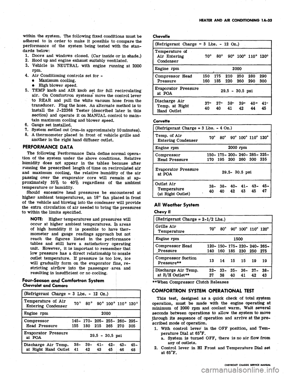
PERFORMANCE DATA
The following Performance Data define normal opera-
tion of the system under the above conditions. Relative
humidity does not appear in the tables because after
running the prescribed length of time on recirculated air
and maximum cooling, the relative humidity of the air
passing over the evaporator core will remain at ap-
proximately 35% to 40% regardless of the ambient
temperature or humidity.
Should excessive head pressures be encountered at
higher ambient temperatures, an 18" fan placed in front
of the vehicle and blowing into the condenser will provide
the extra circulation of air needed to bring the pressures
to within the limits specified.
NOTE: Higher temperatures and pressures will
occur at higher ambient temperatures, fti areas
of high humidity it is possible to have ther-
mometer and gauge readings approach but not
reach the figures listed in the performance
tables and still have a satisfactory operating
unit. However, it is important to remember that
low pressure has a direct relationship to nozzle
outlet temperature. If pressure is too low, ice
will gradually form on the evaporator fins, re-
stricting airflow into the passenger area and
resulting in insufficient or no cooling.
Four-Season and Comfortron System
Chevrolet and Camaro
Chevelle
(Refrigerant
Charge
=
Temperature
of Air
Entering Condenser
Engine rpm
Compressor
Head Pressure
Evaporator Pressure
at POA
Discharge Air Temp,
at Right Hand Outlet
3
Lbs. -
70°
145-
155
38-
41
80°
170-
180
12 02
90°
.)
100°
2000
205-
215
29.5 -
39-
42
41-
43
255-
265
30.5
42-
45
110°
260-
270
psi
43-
46
120°
295-
305
45-
48
(Refrigerant Charge =
Temperature of
Air Entering
Condenser
Engine rpm
Compressor Head
Pressure
Evaporator
Pressure
at
POA
Discharge Air
Temp, at Right
Hand Outlet
3 Lbs. -
70°
150
160
37-
40
80°
175
185
12 Oz.)
90° 100°
2000
210 250
220 260
29.5 - 30.5
37-
40
38-
39-
41 42
110°
280
290
psi
40-
44
120°
290
300
41-
45
Corvette
(Refrigerant Charge =
Temp, of Air
Entering Condenser
Engine rpm
Compressor
Head Pressure
Evaporator
Pressure
at
POA
Outlet
Air
Temperature
(at Right
Outlet)
3
Lbs.
70°
150-
170
38-
40
- 4 Oz.)
80°
175-
195
29
38-
40
90°
2000
200-
200
100°
i*pm
240-
260
110°
285-
300
5-
30.5 psi
40-
42
41-
43
43-
45
120°
325-
335
45-
47
Alt Weather System
Chevy II
(Refrigerant
Charge
=
Grille Air
Temperature
Engine rpm
Compressor Head
Pressure
Compressor Suction
Pressure**
Discharge Air Temp,
at R/H Outlet**
2-1/2 Lbs.)
70°
120-
140
13
32-
37
80°
150-
160
14
CO
OO
CO
CO
90°
100°
1500
175-
185
15
35-
40
220-
230
15
36-
41
110°
240-
250
19
37-
42
120°
265-
275
19
38-
43
**When Compressor Clutch Releases
COMFORTRON SYSTEM OPERATIONAL TEST
This test, designed as a quick check of total system
operation, must be made with the engine operating at
minimum of 2000 rpm and coolant warm. Wait several
seconds between operations to allow the system to move
through its sequence of operation and arrive at the pre-
scribed mode of operation.
1.
With control lever in the OFF position, and Tem-
perature Dial at 65°F.
a. System is turned OFF, there is no air flow from
any of outlets.
2.
Control lever in HI Front and Temperature Dial set
at65°F.
CHEVROLET CHASSIS SERVICE MANUAL
Page 57 of 659
HEATER AND AIR CONDITIONING 1A-34
a. Blower comes on High speed.
b.
Cold air comes from A/C outlets.
3.
Rotate Temperature Dial to 85°F.
a. Blower speed will decrease to Low speed then
increase to Medium or High.
b.
Air temperature changes from Cold to Hot and
comes out heater outlet.
4.
Move control lever to LOW Front, with Temperature
Dial at 85°F. Blower operates at Low and Medium
speeds.
5.
Move control lever to Rear, set Temperature Dial
at 65°F.
a. Blower goes to High speed and maintains high
air flow.
b.
All air comes from A/C outlets.
6. Move control lever to DE-FOG.
a. Blower is on Medium or High Speeds.
b.
Air comes from Defroster and Heater Outlets.
7.
Move control lever to DE-ICE.
a. Blower is on High Speed.
b.
Air temperature goes to warm and most of air
comes from defroster nozzle, with small amount
of air coming from heater outlet.
c. Outside air door is open - (door valve is closed
to car body).
8. Move control lever to REAR (dial at 65°). Outside
air door moves outboard. (Door valve is open to
car body).
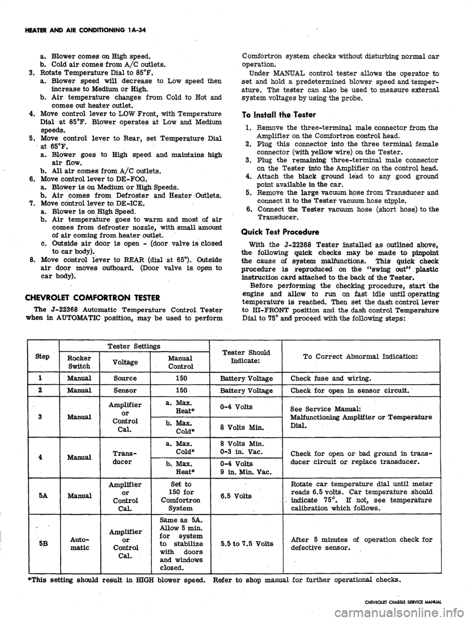
CHEVROLET COMFORTRON TESTER
The J-22368 Automatic Temperature Control Tester
when in AUTOMATIC position, may be used to perform
Comfortron system checks without disturbing normal car
operation.
Under MANUAL control tester allows the operator to
set and hold a predetermined blower speed
and.
temper-
ature. The tester can also be used to measure external
system voltages by using the probe.
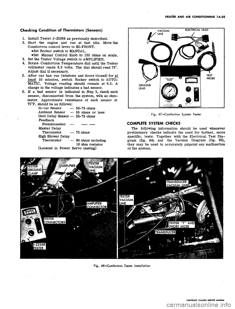
To Install the Tester
1.
Remove the three-terminal male connector from the
Amplifier on the Comfortron control head.
2.
Plug this connector into the three terminal female
connector (with yellow wire)
on
the Tester.
3.
Plug the remaining three-terminal male connector
on the Tester into the Amplifier on the control head.
4.
Attach the black ground lead to any good ground
point available in the car.
5.
Remove the large vacuum hose from Transducer and
connect it to the Tester vacuum hose nipple.
6. Connect the Tester vacuum hose (short hose) to the
Transducer.
Quick Test Procedure
With the J-22368 Tester installed as outlined above,
the following quick checks may be made to pinpoint
the cause of system malfunctions. This quick check
procedure is reproduced on the "swing out" plastic
instruction card attached to the back of the Tester.
Before performing the checking procedure, start the
engine and allow to run on fast idle until operating
temperature is reached. Then set the dash control lever
to HI-FRONT position and the dash control Temperature
Dial to 75° and proceed with the following steps:
Step
1
2
3
4
5A
5B
Tester Settings
Rocker
Switch
Manual
Manual.
Manual
Manual
Manual
Auto-
matic
Voltage
Source
Sensor
Amplifier
or
Control
Cal.
Trans-
ducer
Amplifier
or
Control
Cal.
Amplifier
or
Control
Cal.
Manual
Control
150
150
a. Max.
Heat*
b.
Max.
Cold*
a. Max.
Cold*
b.
Max.
Heat*
Set to
150 for
Comfortron
System
Same as 5A.
Allow 5 min.
for system
to stabilize
with doors
and windows
closed.
Tester Should
Indicate:
Battery Voltage
Battery Voltage
0-4 Volts
8 Volts Min.
8 Volts Min.
0-3 in. Vac.
0-4 Volts
9 in. Min. Vac.
6.5 Volts
5.5 to 7.5 Volts
To Correct Abnormal Indication:
Check fuse and wiring.
Check for open in sensor circuit.
See Service Manual:
Malfunctioning Amplifier or Temperature
Dial.
Check for open or bad ground in trans-
ducer circuit or replace transducer.
Rotate car temperature dial until meter
reads 6.5 volts. Car temperature should
'•- indicate 75°. If not, see temperature
calibration which follows.
After 5 minutes of operation check for
defective sensor.
•This setting should result in HIGH blower speed. Refer to shop manual for further operational checks.
CHEVROLET CHASSIS SERVICE MANUAL
Page 58 of 659
HEATER AND AIR CONDITIONING 1A-35
Checking Condition of Thermistors (Sensors)
1.
Install Tester J-22368 as previously described.
2.
Start the engine and run at fast idle. Move the
Comfortron control lever to HI-FRONT.
•Set Rocker switch to MANUAL.
•Set Manual Control Knob to 150 ohms on scale.
3.
Set the Tester Voltage switch to AMPLIFIER.
4.
Rotate Comfortron Temperature dial until the Tester
voltmeter reads 6.5 volts. The dial should read 75°,
Adjust dial if necessary.
5.
After car has run (windows and doors closed) for at
least 10 minutes, switch Rocker switch to AUTO-
MATIC. Voltage reading should remain at 6.5. A
change in the voltage indicates a bad sensor.
6. If a bad sensor is indicated in Step 5, check each
sensor, disconnected from the system, with an ohm-
meter. Approximate resistance of each sensor at
75°F.
should be as follows:
In-car Sensor — 50-75 ohms
Ambient Sensor --,55 ohms or less
Duct Delay Sensor -.- 25-75 ohms
Feedback
Potentiometer —
Master Delay
Thermistor -- 70 ohms
High Blower Delay
Thermistor -- 80 ohms including
10 ohm resistor
(Located in Power Servo casting)
VACUUM
ELECTRICAL LEAD
GROUND
LEAD
Fig.
47—Comfortron System Tester x
COMPLETE SYSTEM CHECKS
The following information should be used whenever
preliminary checks indicate the need for further, more
specific, tests. Together with the Electrical Test Dia-
gram (fig. 49) and the Vacuum Diagram (fig. 50),
they may be used to accurately pinpoint any malfunction
of the system.
Fig.
48—Comfortron Tester Installation
CHEVROLET OU
SERVICE MANUAL
Page 108 of 659
SECTION
IB
CORVETTE BODY
INDEX
Page
General Description . . * • •.
•
^"i1
Maintenance and Replacements 1B-1
Front End 1B-1
Adjustments IBri
Hood 1B-1
Hood Catch 1B-2
Hood Assembly . 1B-2
Front Emblems 1B-2
Vent Grilles 1B-2
Instrument Panel Tray . 1B-2
Cowl Area Trim
....................
1B-4
Rear View Mirror 1B-4
Outside 1B-4
Inside . 1B-4
Sun Visor . 1B-4
Cowl Ventilator Assembly 1B-4
Windshield ; 1B-5
Doors 1B-7
Adjustments 1B-7
Door Lock Striker 1B-7
Door Window and Vent 1B-7
Door Hinges 1B-7
Trim Panel and Inside Handles IB-11
Weatherstrip 1B-11
Door Ventilator Assembly 1B-12
19437 Model 1B-12
19467 Model 1B-13
Window Glass 1B-13
Glass Run Channel—Upper 1B-14
Window Outer Seal Assembly 1B-14
Window Inner Seal Assembly 1B-14
Glass Run Channel—Rear 1B-15
Window Regulator—Manual 1B-15
Window Regulator—Power 1B-15
Door Lock and Remote Controls 1B-16
Outer Handle . 1B-16
Lock Cylinder 1B-17
Hinges—Door Assembly . 1B-17
Rear Quarter .. . 1B-19
Door Sill and Molding . . 1B-19
Rear End . . r 1B-19
Folding Top Compartment Lid 1B-19
Adjustments . . 1B-19
1B-19
Page
Lock 1B-19
Control 1B-19
Rear Window—19437 Model 1B-21
Gas Tank Door and Rear Trim Plate.,. . . . . . . . 1B-23
Rear Filler Panel 1B-23
Spare Tire Mount 1B-23
Rugs and Interior Trim 1B-25
Cleaning Soft Trim 1B-25
Carpets and Covers—All Models 1B-26
Rear Body Trim , . 1B-26
Soft Covers 1B-26
Rigid Plastic Trim 1B-26
Garnish Moldings Plus-Headliner-19437 Model . . 1B-27
Seats 1B-27
Body Mounting 1B-27
Body Repairs . 1B-27
General Instructions . . . 1B-27
Repair Panels. 1B-28
Precautions 1B-29
Plastic Solder Kit 1B-29
Resin Kit 1B-30
Specific Repairs 1B-32
Scratched Panels-Spot Refinishing 1B-32
Dents in Panels-Surface Cracks !B-33
Cracked Panels . . 1B-35
Fractures 1B-37
Panel Replacement 1B-39
Hard Top . . 1B-41
Care and Storage 1B-41
Rear Window 1B-41
Garnish Moldings and Latches 1B-42
Headlining 1B-43
Weatherstrips and Drip Molding 1B-43
Vinyl Covering . 1B-43
Folding Top 1B-46
Care of Folding Top 1B-46
Care of Rear Window 1B-46
Adjustments 1B-48
Top Assembly, Removal and Installation 1B-49
Top Trim and Rear Window Assembly 1B-50
Frame and Linkage 1B-52
Weatherstrip 1B-52
Adding Hardtop 1B-52
Special Tools 1B-53
GENERAL DESCRIPTION
.
A
structural network
of
steel forms the backbone
of
the
Corvette body. When combined with
the
fiber-glass
re-
inforced plastic body panels,
the
steel-plastic marriage
results
in a
body with increased torsional rigidity
and
greater beaming strength.
Convertible models continue with two roof styles:
the
folding
top
and the removable hardtop. In operation, both
tops function similar to those
of
previous models. Either
top
is
standard and both
are
optional
as
determined by
the top selected
as
base equipment.
MAINTENANCE
&
REPLACEMENTS
FRONT
END
ADJUSTMENTS
(Refer to Figure
2)
Adjustments should
be
made
in
order
-
hood position
first, then catch adjustments.
Hood
The position
of the
hood
in
relation
to
the hood body
opening and the fender surfaces
is
controlled by the posi-
tion
of the
hinges and position
and
adjustment
of
catch
and bumpers.
The fore
and aft
position
of the
hood may be adjusted
CHEVROLET CHASSIS SERVICE MANUAL
Page 114 of 659

CORVETTE BODY
1B-7
HEAT
CONTROL
€P-
CABLE
VIEW A
HOOD RELEASE
Fig.
11—Cowl Ventilator
and
Controls
and reveal moldings; upper garnish molding; lower
garnish molding; side garnish molding; header latch
plates on 19467 Models and rear view mirror.
11.
Clean
up
excess sealer
and
cement with rag damp-
ened with oleum spirits, prep-sol
or
kerosene;
in-
stall wiper arm assemblies.
DOORS
ADJUSTMENTS
Door Lock Striker
Door lock strikers incorporate
an
inter-lock feature
consisting
of a
notch
in the
striker into which the lock
bolt housing extension engages. With
the
inter-lock
feature
it is
very important that
the
lock extension en-
gages properly
in the
striker notch
and
that, where
necessary,
the
correct striker emergency spacers
are
used to obtain proper engagement.
1.
To
adjust striker
up,
down,
in, or
out loosen striker
plate screws and shift striker and adjusting plates
as
required, then tighten screws.
2.
To determine
if
door lock striker emergency spacers
are required, apply modeling clay
or
body caulking
compound
in the
door lock striker notch where
the
lock extension engages,
and
then close
the
door
to
form
a
measurable impression in the clay
or
caulk-
ing compound,
as
shown
in
Figure
24.
Remove
all
clay
or
compound when adjustment
is
completed.
When dimension
"A"
from inside face
of
striker teeth
to center
of
lock extension
is
less than 3/16", install
emergency spacers
and
proper length striker attaching
screws.
NOTE:
Dimension
"B"
from center
of
lock
extension
to
inside face
of
striker notch should
.
never be less than 1/8".
If check indicates need
for
emergency spacers,
pro-
ceed
as
follows:
1.
With pencil, scribe position
of
striker on body pillar.
2.
Remove three door lock striker attaching screws and
remove striker
and
adjusting plates from pillar.
3.
To
install, place striker, shims and adjusting plates
within scribe marks
on
pillar
and
tighten screws.
IMPORTANT: Whenever
a
door
has
been
re-
moved
and
installed,
or
realigned,
the
door
SHOULD NOT be closed completely until
a
visual
check
is
made to determine
if
the lock extension/
will engage
in the
striker notch. Where
re-
quired, door lock striker emergency spacers
should
be
installed
so
that door
can be
closed
and
an
accurate check made to determine emer-
gency spacer requirements.
Door Window and Vent Adjustment
To move
the top of the
window
in or
out, the bottom
ends
of
both
run
channels
are
adjustable.
The
rear
channel
is
adjusted
by
loosening
the
lower
of
the two
screws
on the
rear face
of
door, "C" Figure 25, and
moving channel
as
necessary.
The
front channel
is ad-
justed
by
removing
the
trim pad and moving the Channel
in
or out by a
stud
and nut
adjustment, "B" Figure 25.
The
top end of the
rear channel
is
not adjustable in
or
out.
On 19467 models
an
adjustment
may be
made
to the
closed-door relationship
of the
vent assembly
to the
windshield frame. This adjustment
is
controlled
by the
stud-nut assembly "B" Figure
25.
The closed position
of the
window
is
controlled
by
bumper assemblies located
at
each end
of
window frame
as shown
in
Figure
26.
^
Access
to
bumper retaining
screw
may be
gained through holes
"D" and
"E"
in
Figure
25.
Door Hinges
The position
of the
door assembly in the body opening
is adjusted
by the
striker plate position covered
pre-
viously
and the
position
of the
door
on
the hinge rear
CHEVROLET
a
SERVICE
Page 118 of 659

CORVETTE BODY 1B-11
CLAYOfc
CAULKING
COMPOUND
Fig. 26-Window Rear Stop - Typical
Fig. 24—Checking Adjustment of Striker
3.
Adjust door as required. Location of hinge retaining
bolts may be seen in Figure 25 at "A". Do not allow
doors to hang on one hinge without support.
4.
Install trim pad and lubricate door "hold opens" and
hinges with Lubriplate or its equivalent.
NOTE:
After performing any door adjustment,
the window and door post should be checked for
alignment and adjusted as necessary. In addi-
tion,
never slam the door after adjustment with-
out first checking the door lock and striker plate
engagement. An adjustment may be necessary.
TRIM PANEL, AND INSIDE HANDLES
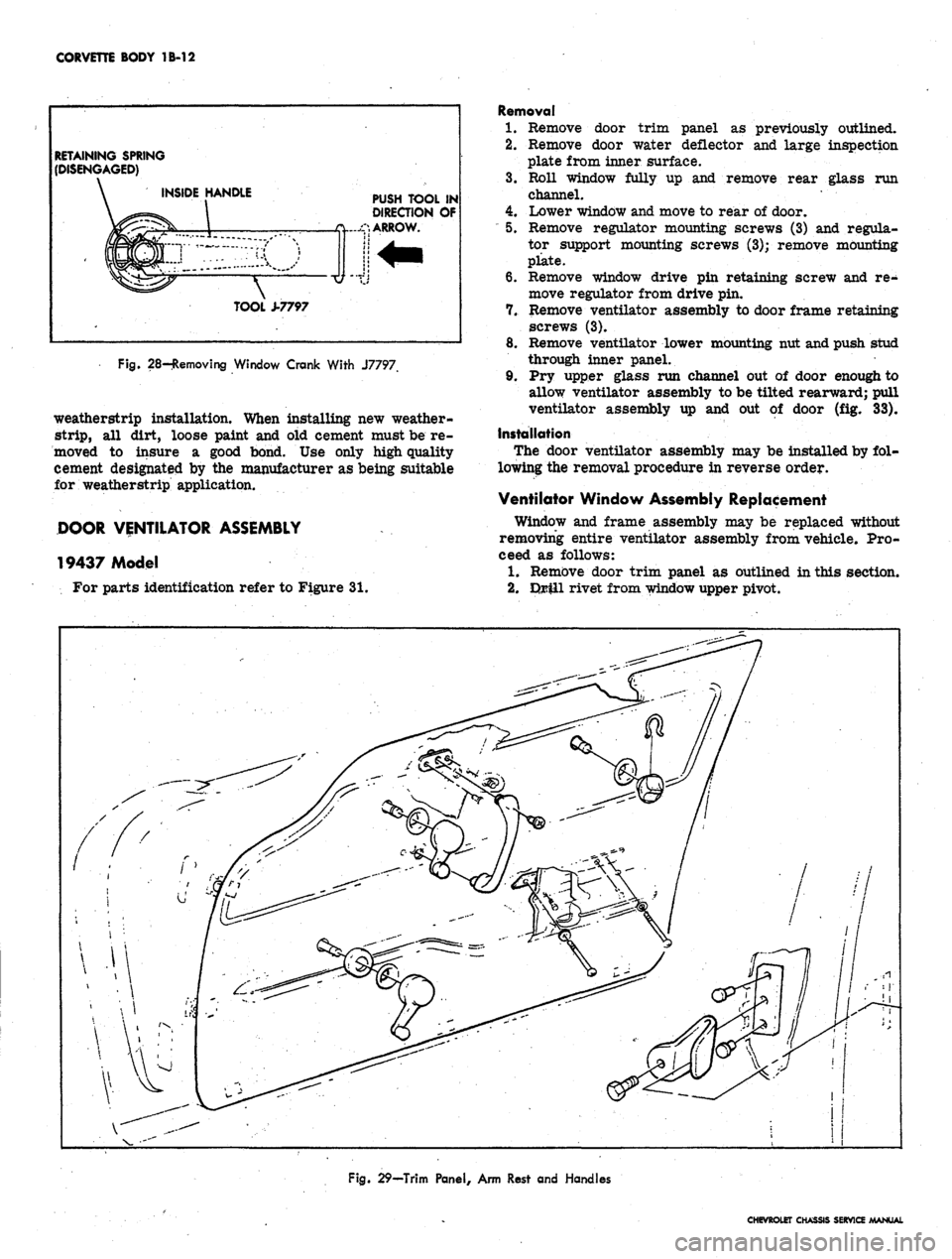
Figure 29 is an exploded view of integral arm rest,
inside handles, and trim panel fastenings.
Removal of trim panel may be accomplished as
follows:
1.
Remove two screws under arm rest.
2.
Using Tool J-7797, remove clips retaining window
crank and lock remote control as shown in Figure 28.
3.
Remove knob from door lock control by turning
counter-clockwise.
4.
Remove 2 screws retaining inside pull handle.
5. Remove sheet metal screws and special washers
retaining trim panel to door assembly.
6. Pull trim panel out. at bottom, tap bottom edge of
trim panel with hand to disengage from top of door.
Remove trim panel from vehicle.
WEATHERSTRIP
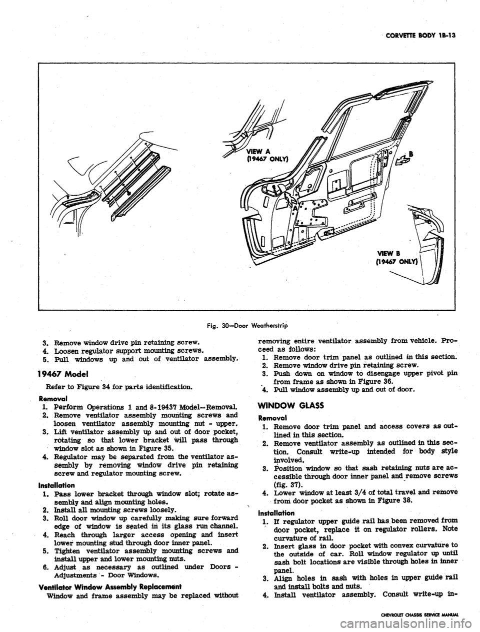
Figure
30
illustrates both 19437 and 19467 model door
COWL
Fig.
25-Door Adjustment Points
Fig.
27-Door Hinge
CHEVROLET CHASSIS SERVICE MANUAL
Page 119 of 659
CORVETTE BODY 1B-12
RETAINING SPRING
(DISENGAGED)
INSIDE HANDLE
PUSH TOOL IN
DIRECTION OF
ARROW.
TOOL ±7797
Fig. 28-Removing Window Crank With J7797
weatherstrip installation. When installing new weather-
strip,
all dirt, loose paint and old cement must be re-
moved to insure a good bond. Use only high quality
cement designated by the manufacturer as being suitable
for weatherstrip application.
DOOR VENTILATOR ASSEMBLY
19437 Model
For parts identification refer to Figure 31.
Removal
1.
Remove door trim panel as previously outlined.
2.
Remove door water deflector and large inspection
plate from inner surface.
3.
Roll window fully up and remove rear glass run
channel. •
4.
Lower window and move to rear of door.
"
5. Remove regulator mounting screws (3) and regula-
tor support mounting screws (3); remove mounting
plate.
6. Remove window drive pin retaining screw and re-
move regulator from drive pin.
7. Remove ventilator assembly to door frame retaining
screws (3).
8. Remove ventilator lower mounting nut and push stud
through inner panel.
9. Pry upper glass run channel out of door enough to
allow ventilator assembly to be tilted rearward; pull
ventilator assembly up and out of door (fig. 33).
Installation
The door ventilator assembly may be installed by fol-
lowing the removal procedure in reverse order.
Ventilator Window Assembly Replacement
Window and frame assembly may be replaced without
removing entire ventilator assembly from vehicle. Pro-
ceed as follows:
1.
Remove door trim panel as outlined in this section.
2.
Drill rivet from window upper pivot.
Fig. 29—Trim Panel, Arm Rest and Handles
CHEVROLET CHASSIS SERVICE MANUAL
Page 120 of 659
CORVETTE BODY 1B-13
Fig.
30-Door Weatherstrip
3.
Remove window drive pin retaining screw.
4.
Loosen regulator support mounting screws.
5. Pull windows up and out of ventilator assembly.
19467 Model
Refer to Figure 34 for parts identification.
Removal
1.
Perform Operations 1 and 8-19437 Model-Removal.
2.
Remove ventilator assembly mounting screws and
loosen ventilator assembly mounting nut - upper.
3.
Lift ventilator assembly up and out of door pocket,
rotating so that lower bracket will pass through
window slot as shown in Figure 35.
4.
Regulator may be separated from the ventilator as-
sembly by removing window drive pin retaining
screw and regulator mounting screw.
Installation
1.
Pass lower bracket through window slot; rotate as-
sembly and align mounting holes*
2.
Install all mounting screws loosely.
3.
Roll door window up carefully making sure forward
edge of window is seated in its glass run channel.
4.
Reach through larger access opening and insert
lower mounting stud through door inner panel.
5. Tighten ventilator assembly mounting screws and
install upper and lower mounting nuts.
6. Adjust as necessary as outlined under Doors -
Adjustments - Door Windows.
Ventilator Window Assembly Replacement
Window and frame assembly may be replaced without
removing entire ventilator assembly from vehicle. Pro-
ceed as follows:
1.
Remove door trim panel as outlined in this section.
2.
Remove window drive pin retaining screw.
3.
Push down on window to disengage upper pivot pin
from frame as shown in Figure 36.
4.
Pull window assembly up and out of door.
WINDOW GLASS
Removal
1.
Remove door trim panel and access covers as out-
lined in this section.
2.
Remove ventilator assembly as outlined in this sec+
tion.
Consult write-up intended for body style
involved.
Position window so that sash retaining nuts are ac-
cessible through door inner panel and remove screws
(fig. 37).
Lower window at least 3/4 of total travel and remove
3.
4.
from door pocket as shown in Figure 38.
Installation
1.
If regulator upper guide rail has been removed from
door pocket, replace it on regulator rollers. Note
curvature of rail.
2.
Insert glass in door pocket with convex curvature to
the outside of car. Roll window regulator up until
sash bolt locations are visible through holes in inner
panel.
3.
Align holes in sash with holes in upper guide rail
and install bolts and nuts.
4.
Install ventilator assembly. Consult write-up in-
CHEVROLETCH>
SERVICE