window CHEVROLET CAMARO 1967 1.G Chassis User Guide
[x] Cancel search | Manufacturer: CHEVROLET, Model Year: 1967, Model line: CAMARO, Model: CHEVROLET CAMARO 1967 1.GPages: 659, PDF Size: 114.24 MB
Page 121 of 659
CORVETTE BODY
1B-14
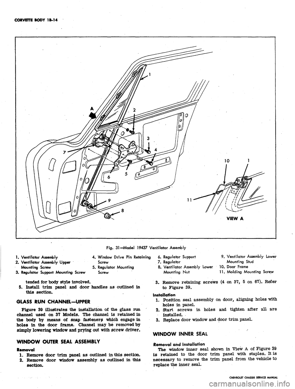
Fig.
31-Mpdei 19437 Ventilator Assembly
1.
Ventilator Assembly
2.
Ventilator Assembly Upper
Mounting Screw
3. Regulator Support Mounting Screw
4.
Window Drive
Pin
Retaining
Screw
5. Regulator Mounting
Screw
tended
for
body style involved.
5. Install trim panel
and
door handles
as
outlined
in
this section.
GLASS
RUN
CHANNEL-UPPER
Figure
39
illustrates
the
installation
of the
glass
run
channel used
on 37
Models.
The
channel
is
retained
in
the body
by
means
of
snap fasteners which engage
in
holes
in the
door frame. Channel
may be
removed by
simply lowering window and prying out with screw driver.
WINDOW OUTER SEAL ASSEMBLY
Removal
1.
Remove door trim panel
as
outlined in this section.
2.
Remove door window assembly
as
outlined
in
this
section.
6. Regulator Support
7. Regulator
8. Ventilator Assembly Lower
Mounting
Nut
9. Ventilator Assembly Lower
Mounting Stud
10.
Door Frame
11.
Molding Mounting Screw
3.
Remove retaining screws (4 on 37, 5 on 67). Refer
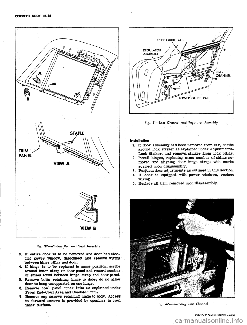
to Figure 39.
Installation
1.
Position seal assembly on door, aligning holes with
holes in panel.
2.
Start screws in holes and tighten after all are
installed.
3.
Replace door window and door trim panel.
WINDOW INNER SEAL
Removal and Installation
The window inner seal shown in View A of Figure 39
is retained to the door trim panel with staples. It is
necessary to remove the trim panel from the vehicle to
replace the inner seal.
CHEVROLET CHASSIS SERVICE MANUAL
Page 122 of 659
CORVETTE BODY 1B-15
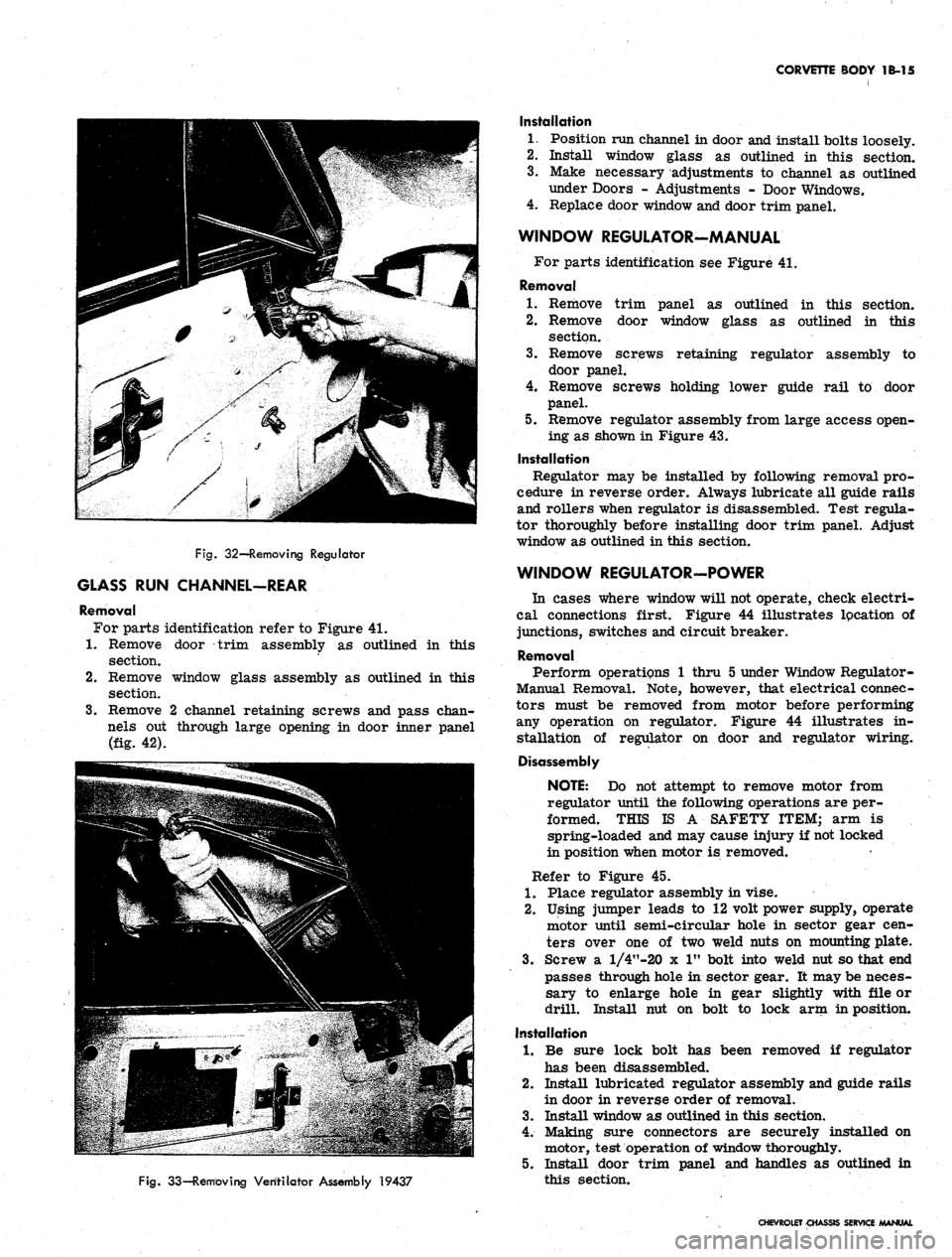
Fig.
32—Removing Regulator
GLASS RUN CHANNEL-REAR
Removal
For parts identification refer to Figure 41.
1.
Remove door trim assembly as outlined in this
section.
2.
Remove window glass assembly as outlined in this
section.
3.
Remove 2 channel retaining screws and pass chan-
nels out through large opening in door inner panel
(fig. 42).
Fig.
33—Removing Ventilator Assembly 19437
Installation
1.
Position run channel in door and install bolts loosely.
2.
Install window glass as outlined in this section.
3.
Make necessary adjustments to channel as outlined
under Doors - Adjustments - Door Windows.
4.
Replace door window and door trim panel.
WINDOW REGULATOR-MANUAL
For parts identification see Figure 41.
Removal
1.
Remove trim panel as outlined in this section.
2.
Remove door window glass as outlined in this
section.
3.
Remove screws retaining regulator assembly to
door panel.
4.
Remove screws holding lower guide rail to door
panel.
5. Remove regulator assembly from large access open-
ing as shown in Figure 43.
Installation
Regulator may be installed by following removal pro-
cedure in reverse order. Always lubricate all guide rails
and rollers when regulator is disassembled. Test regula-
tor thoroughly before installing door trim panel. Adjust
window as outlined in this section.
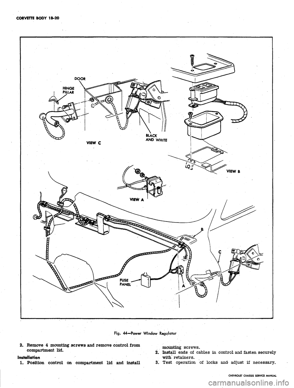
WINDOW REGULATOR-POWER
In cases where window will not operate, check electri-
cal connections first. Figure 44 illustrates lpcation of
junctions, switches and circuit breaker.
Removal
Perform operations 1 thru 5 under Window Regulator-
Manual Removal. Note, however, that electrical connec-
tors must be removed from motor before performing
any operation on regulator. Figure 44 illustrates in-
stallation of regulator on door and regulator wiring.
Disassembly
NOTE:
Do not attempt to remove motor from
regulator until the following operations are per-
formed. THIS IS A SAFETY ITEM; arm is
spring-loaded and may cause injury if not locked
in position when motor is removed.
Refer to Figure 45.
1.
Place regulator assembly in vise.
2.
Using jumper leads to 12 volt power supply, operate
motor until semi-circular hole in sector gear cen-
ters over one of two weld nuts on mounting plate.
3.
Screw a l/4"-20 x 1" bolt into weld nut so that end
passes through hole in sector gear. It may be neces-
sary to enlarge hole in gear slightly with file or
drill. Install nut on bolt to lock arm in position.
Installation
1.
Be sure lock bolt has been removed if regulator
has been disassembled.
2.
Install lubricated regulator assembly and guide rails
in door in reverse order of removal.
3.
Install window as outlined in this section.
4.
Making sure connectors are securely installed on
motor, test operation of window thoroughly.
5. Install door trim panel and handles as outlined in
this section.
CHEVROLET CHASSIS SERVICE MANUAL
Page 123 of 659

CORVETTE
BODY
1B-16
1.
Ventilator Assembly
2.
Ventilator Assembly Mounting
Screw
3.
Window Drive
Pin
Retaining Screw
4.
Regulator Mounting Screw
Fig.
34-Model 19467 Ventilator Assembly
5. Regulator
6. Ventilator Assembly Mounting
Nut - Upper
7. Ventilator Assembly Mounting
Stud - Upper
8. Ventilator Assembly Mounting
Stud - Lower
9. Ventilator Assembly Mounting
Nut -
•
Lower
DOOR LOCK AND REMOTE CONTROLS
For parts identification refer to Figure 46.
Removal
1.
Roll door window fully up.
2.
Remove door trim panel as outlined in this section.
3.
Remove two screws holding door lock remote con-
trol assembly and disengage control from lock re-
mote control rod.
4.
Remove cover from larger access hole in door inner
panel.
5. Remove two screws retaining remote locking control
assembly and disengage control from remote control
locking rod.
6. Remove 4 screws retaining lock assembly, disengage
control rods and remove lock from door pocket.
Installation
To install lock and controls follow removal assembly
in reverse order. All components should be lubricated
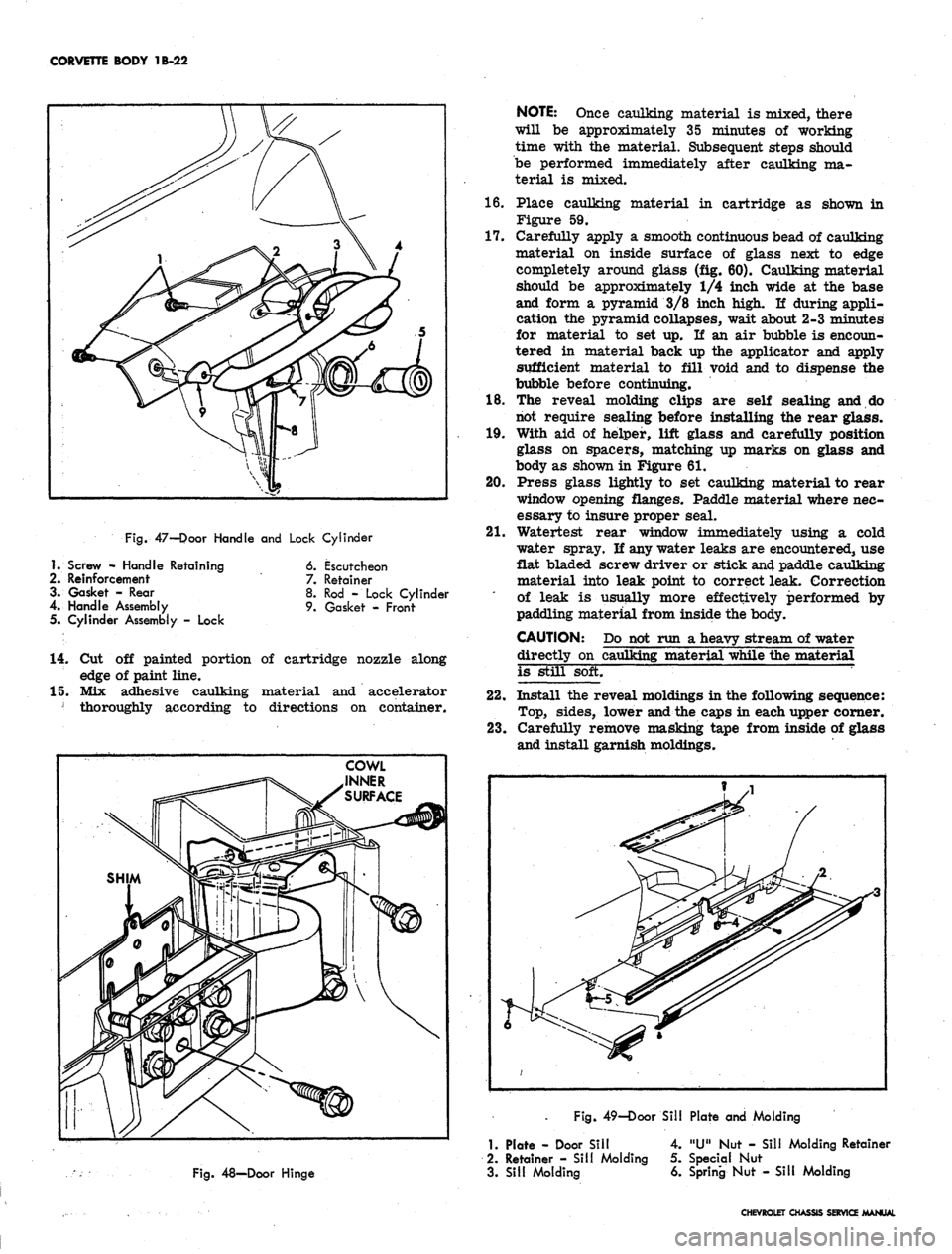
before installation.
OUTER HANDLE
For parts identification refer to Figure 47.
Removal
1.
Remove door trim panel as outlined in this section.
Remove larger access hole cover.
2.
Roll door window fully up.
3.
Working through access hole, remove 2 door handle
retaining screws.
4.
Remove handle from door outer surface. Retrieve
reinforcement from inside door pocket. Discard old
Installation
1.
Install new gaskets and position door handle on door
outer panel.
2.
Position reinforcement on door inner panel and in-
stall handle retaining screws.
3.
Carefully check operation of door lock.
4.
Install door trim panel as outlined in this section.
CHEVROLET CHASSIS SERVICE MANUAL
Page 124 of 659
CORVETTE BODY 1B-17
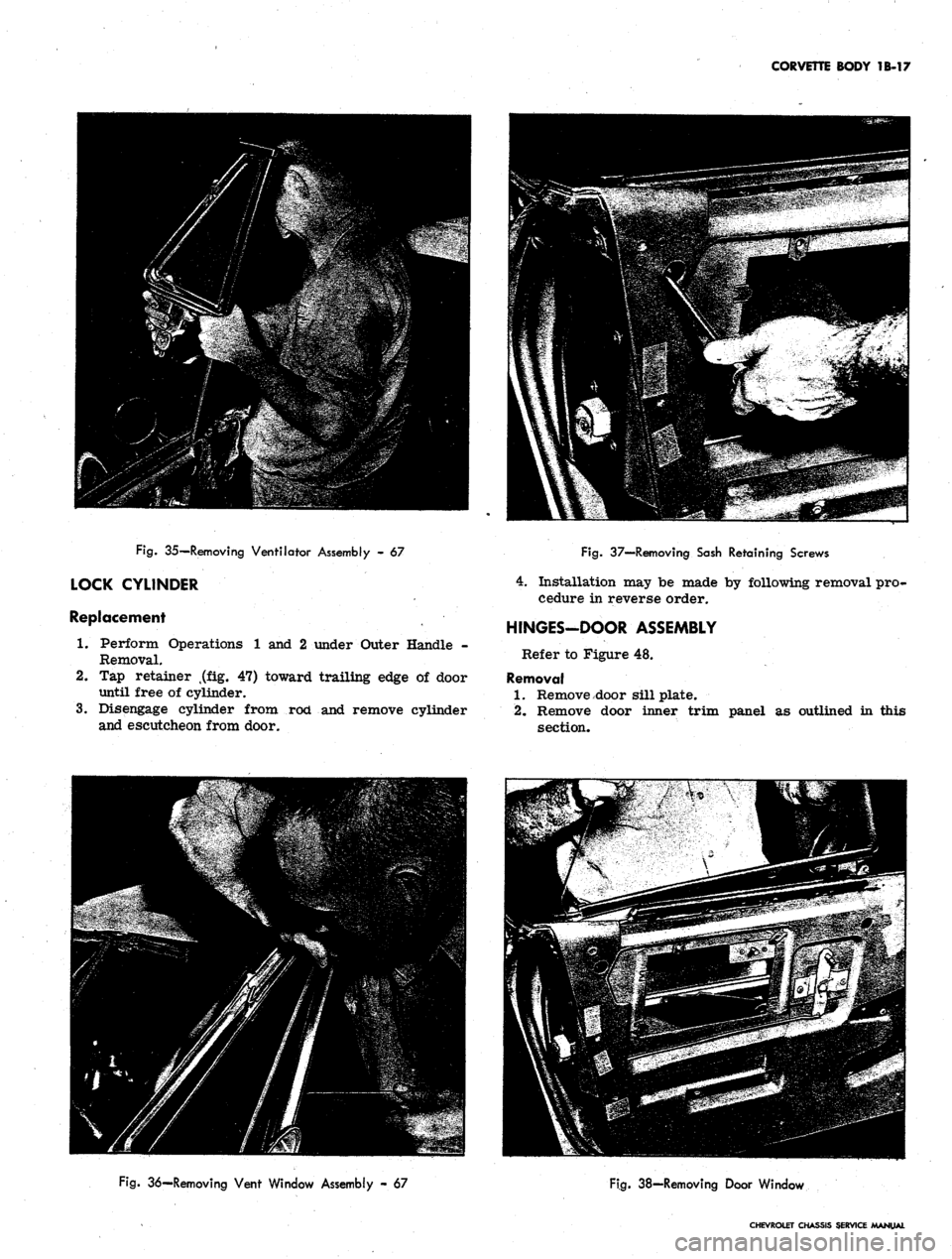
Fig.
35—Removing Ventilator Assembly - 67
LOCK CYLINDER
Replacement
1.
Perform Operations 1 and 2 under Outer Handle -
Removal.
2.
Tap retainer t(flLg. 47) toward trailing edge of door
until free of cylinder.
3.
Disengage cylinder from rod and remove cylinder
and escutcheon from door.
Fig.
37—Removing Sash Retaining Screws
4.
Installation may be made by following removal pro-
cedure in reverse order.
HINGES-DOOR ASSEMBLY
Refer to Figure 48.
Removal
1.
Remove door sill plate.
2.
Remove door inner trim panel as outlined in this
section.
Fig.
36—Removing Vent Window Assembly - 67
Fig.
38-Removing Door Window
CHEVROLET CHASSIS SERVICE /MANUAL
Page 125 of 659
CORVETTE BODY 18-18
TRIM
PANEL
VIEW A
view B
UPPER GUIDE
\
REGULATOR / /
ASSEMBLY / A-
RAIL ,
MS
o Y \ C^^^
Jlf
3) \ JJ
LOWER GUIDE RAIL
y
< REAR
/ CHANNEL
Fig.
41—Rear Channel and Regulator Assembly
Installation
1.
If door assembly has been removed from car, scribe
around lock striker as explained under Adjustments-
Lock Striker, and remove, striker from lock pillar.
2.
Install hinges, replacing same number of shims re-
moved and aligning door hinge straps with marks
scribed upon disassembly.
3.
Perform door adjustments as outlined in this section.
4.
If door is equipped with power windows, replace
wiring.
5.
Replace all trim removed upon disassembly.
Fig.
39—Window Run and Seal Assembly
3.
If entire door is to be removed and door has elec-
tric power window, disconnect and remove wiring
between hinge pillar and door.
4.
If hinge is to be replaced in same position, scribe
around inner strap on door panel and record number
of shims found between hinge strap and door panel.
5. Remove bolts retaining hinge to door; do no allow
door to hang unsupported on one hinge.
6. Remove cowl panel inner trim as explained under
Front End-Cowl Area and Console Trim-.
7. Remove cap screws retaining hinge to body. Access
to forward screws is provided by openings in cowl
inner surface.
Fig.
42—Removing Rear Channel
CHEVROLET CHASSIS SERVICE MANUAL
Page 127 of 659
CORVETTE BODY
1B-20
DOOR
Fig.
44—Power Window Regulator
2.
Remove
4
mounting screws and remove control from
compartment
lid.
Installation
*
1.
Position control
on
compartment
lid and
install
mounting screws.
2.
Install ends of cables in control and fasten securely
with retainers.
3.
Test operation of locks and adjust if necessary.
CHEVROLET CHASSIS SERVICE MANUAL
Page 128 of 659

CORVETTE BODY 1B-21
Fig.
45—
Locking Regulator Arm in Place
REAR WINDOW-ADHESIVE CAULKED-
19437 MODEL
For parts identification refer to Figure 55.
1.
Remove the 2 rear window garnish moldings by re-
moving the 14 attaching screws.
2.
Pry molding caps from reveal moldings.
3.
Carefully remove lower, side, and top reveal mold-
ings after marking their position on body with tape.
4.
Secure one end of steel music wire to piece of wood
for handle. Insert other end through caulking mater-
ial at lower corner of rear window; then secure end
of wire to another piece of wood (fig. 56).
5. With the aid of helper, carefully cut through caulking
material (using a sawing motion) with the steel wire;
up side of window, across top, down opposite side,
and across bottom of window.
6. Remove old glass from window opening.
7. Using a sharp scraper or wood chisel, remove ad-
hesive caulking material from body pinchweld flange.
NOTE:
It is not necessary to clean off all the
old caulking material completely from body
opening; however, there should not be any loose
pieces of caulking material left in the opening.
8. Check all reveal molding retaining clips for damage
(24 required). Replace those that are bent or dis-
torted with clips provided in kit.
9. Using weatherstrip adhesive, cement rubber spacers
at bottom, sides, and top of window opening. The
step-type spacers are used at bottom and sides, the
flat type are used at the top, sides, and bottom of
window opening as shown on Figure 55.
10.
Using suction cup holders, position replacement
glass in body opening. Carefully check relationship
of glass to body pinchweld completely around open-
ing. The overlap of glass to body pinchweld and re-
taining flanges should be equal with a minimum over-
lap of 3/16M. Where necessary, position shims under
the lower spacers to obtain required overlap of glass
to body upper and lower flanges.
11.
After proper glass to pinchweld relationship has
been attained, mark position with grease pencil on
glass and body as shown in Figure 57.
12.
Remove glass from body opening and place on pro-
tected surface.
13.
Clean inside edge surface of glass so that glass is
free of any foreign material (oil, grease, etc.).
Using 3/4" masking tape, place tape approximately
1/2 inch from edge of inside surface of glass com-
pletely around glass. Then apply a film of silane
primer to inside edge surface completely around
glass,
also apply silane primer to sealing surface
of pinchweld as shown in Figure 58.
Fig.
46—Door Lock and Remote Controls
1.
Door Lock Remote Control
Assembly
2.
Door Lock Remote Control Knob
3. Door Lock Remote Control Rod
4.
Remote Control Locking Rod
5. Remote Locking Control
Assembly
6. Lock Assembly
CHEVROLET CHASSIS SERVICE MANUAL
Page 129 of 659
CORVETTE BODY 1B-22
16.
17.
Fig.
47-Door Handle and Lock Cylinder
18.
19.
20.
21.
1.
Screw - Handle Retaining
2.
Reinforcement
3. Gasket - Rear
4.
Handle Assembly
5. Cylinder Assembly - Lock
6. Escutcheon
7.
Retainer
8. Rod - Lock Cylinder
9. Gasket - Front
14.
Cut off painted portion of cartridge nozzle along
edge of paint line.
15.
Mix adhesive caulking material and accelerator
] thoroughly according to directions on container.
NOTE:
Once caulking material is mixed, there
will be approximately 35 minutes of working
time with the material. Subsequent steps should
be performed immediately after caulking ma-
terial is mixed.
Place caulking material in cartridge as shown in
Figure 59.
Carefully apply a smooth continuous bead of caulking
material on inside surface of glass next to edge
completely around glass (fig. 60). Caulking material
should be approximately 1/4 inch wide at the base
and form a pyramid 3/8 inch high. If during appli-
cation the pyramid collapses, wait about 2-3 minutes
for material to set up. If an air bubble is encoun-
tered in material back up the applicator and apply
sufficient material to fill void and to dispense the
bubble before continuing.
The reveal molding clips are self sealing and do
not require sealing before installing the rear glass.
With aid of helper, lift glass and carefully position
glass on spacers, matching up marks on glass and
body as shown in Figure 61.
Press glass lightly to set caulking material to rear
window opening flanges. Paddle material where nec-
essary to insure proper seal.
Watertest rear window immediately using a cold
water spray. If any water leaks are encountered, use
flat bladed screw driver or stick and paddle caulking
material into leak point to correct leak. Correction
of leak is usually more effectively performed by
paddling material from inside the body.
CAUTION: Do not run a heavy stream of water
directly on caulking material while the material
is still soft.
22.
Install the reveal moldings in the following sequence:
Top,
sides, lower and the caps in each upper corner.
23.
Carefully remove masking tape from inside of glass
and install garnish moldings.
Fig.
49—Door Sill Plate and Molding
Fig.
48—Door Hinge
1.
Plate - Door Sill
2.
Retainer - Sill Molding
3. Sill Molding
4.
"U" Nut - Sill Molding Retainer
5. Special Nut
6. Spring Nut - Sill Molding
CHEVROLET CHASSIS SERVICE MANUAL
Page 132 of 659
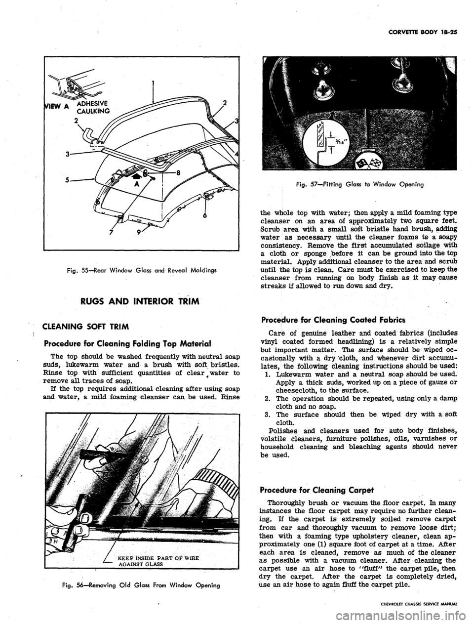
CORVETTE BODY 1B-25
Fig.
55—Rear Window G!as.s arid Reveal Moldings
RUGS AND INTERIOR TRIM
Fig.
57—Fitting Glass to Window Opening
the whole top with water; then apply a mild foaming type
cleanser on an area of approximately two square feet.
Scrub area with a small soft bristle hand brush, adding
water as necessary until the cleaner foams to a soapy
consistency. Remove the first accumulated soilage with
a cloth or sponge before it can be ground into the top
material. Apply additional cleanser to the area and scrub
until the top is clean. Care must be exercised to keep the
cleanser from running on body finish as it may cause
streaks if allowed to run down and dry.
CLEANING SOFT TRIM
Procedure for Cleaning Folding Top Material
The top should be washed frequently with neutral soap
suds,
lukewarm water and a brush with soft bristles.
Rinse top with sufficient quantities of clear # water to
remove all traces of soap.
If the top requires additional cleaning after using soap
and water, a mild foaming cleanser can be used. Rinse
KEEP INSIDE PART OF WIRE
AGAINST GLASS
Fig.
56—Removing Old Glass From Window Opening
Procedure for Cleaning Coated Fabrics
Care of genuine leather and coated fabrics (includes
vinyl coated formed headlining) is a relatively simple
but important matter. The surface should be wiped oc-
casionally with a dry cloth, and whenever dirt accumu-
lates,
the following cleaning instructions should be used:
1.
Lukewarm water and a neutral soap should be used.
Apply a thick suds, worked up on a piece of gauze or
cheesecloth, to the surface.
2.
The operation should be repeated, using only a damp
cloth and no soap.
3.
The surface should then be wiped dry with a soft
cloth.
Polishes and cleaners used for auto body finishes,
volatile cleaners, furniture polishes, oils, varnishes or
household cleaning and bleaching agents should never
be used.
Procedure for Cleaning Carpet
Thoroughly brush or vacuum the floor carpet, in many
instances the floor carpet may require no further clean-
ing. If the carpet is extremely soiled remove carpet
from car and thoroughly vacuum to remove loose dirt;
then with a foaming type upholstery cleaner, clean ap-
proximately one (1) square foot of carpet at a time. After
each area is cleaned, remove as much of the cleaner
as possible with a vacuum cleaner. After cleaning the
carpet use an air hose to
"fluff"
the carpet pile, then
dry the carpet. After the carpet is completely dried,
use an air hose to again fluff the carpet pile.
CHEVROLET CHASSIS SERVICE MANUAL
Page 133 of 659
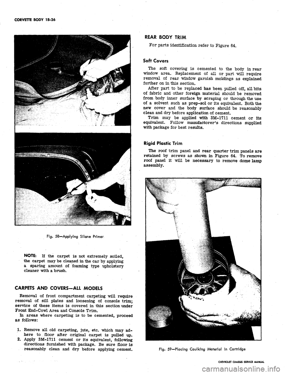
CORVETTE BODY 1B-26
Fig.
58—-Applying Silqne Primer
NOTE: If the carpet is not extremely soiled,
the carpet may be cleaned in the car by applying
a sparing amount of foaming type upholstery
cleaner with a brush.
CARPETS AND COVERS-ALL MODELS
Removal of front compartment carpeting will require
removal of sill plates and loosening of console trim;
service of these items is covered in this section under
Front End-Cowl Area and Console Trim.
In areas where carpeting is to be cemented, proceed
as follows:
1.
Remove all old carpeting, jute, etc. which may ad-
here to floor after original carpet is pulled up.
2.
Apply 3M-1711 cement or its equivalent, following
directions furnished with package. Be sure floor is
reasonably clean and dry before applying cement.
REAR BODY TRIM
For parts identification refer to Figure 64.
Soft Covers
The soft covering is cemented to the body in rear
window area. Replacement of all or part will require
removal of rear window garnish moldings as explained
further on in this section.
After part to be replaced has been pulled off, all bits
of fabric and other foreign material should be removed
from body inner surface by scraping or through the use
of a solvent such as prep-sol or its equivalent. Both the
new cover and the body surface should be reasonably-
clean and dry before application of cement.
Trim may be applied with 3M-1711 cement or its
equivalent. Follow manufactorer's directions supplied
with package for best results.
Rigid Plastic Trim
The roof trim panel and rear quarter trim panels are
retained by screws as shown in Figure 64. To remove
roof panel it will be necessary to remove dome lamp
assembly.
Fig.
59—Placing Caulking Material In Cartridge
CHEVROLET CHASSIS SERVICE MANUAL