window CHEVROLET CAMARO 1967 1.G Chassis Owner's Guide
[x] Cancel search | Manufacturer: CHEVROLET, Model Year: 1967, Model line: CAMARO, Model: CHEVROLET CAMARO 1967 1.GPages: 659, PDF Size: 114.24 MB
Page 154 of 659
CORVETTE BODY
1B-47
REAR
BOW
ASSY.
VIEW
C
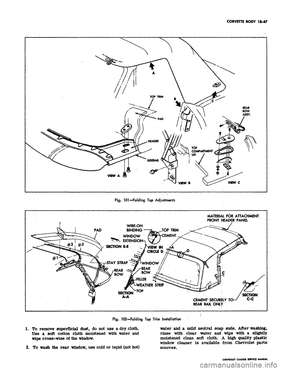
Fig.
101—Folding
Top
Adjustments
MATERIAL
FOR
ATTACHMENT
FRONT HEADER PANEL
PAD
WIRE-ON
BINDING
WINDOW
EXTENS
SECTION
E-E
AY STRAP
SECTION
A-A
CEMENT SECURELY
REAR RAIL ONLY
Fig.
102—Folding
Top
Trim Installation
1.
To
remove superficial dust,
do not use a
dry cloth.
Use
a
soft cotton cloth moistened with water
and
wipe cross-wise
of
the window.
2.
To
wash
the
rear window,
use
cold or tepid (not hot)
water
and a
mild neutral soap suds. After washing,
rinse with clear water
and
wipe with
a
slightly
moistened clean soft cloth.
A
high quality plastic
window cleaner
is
available from Chevrolet parts
sources.
CHEVROLET
Oi
SERVia
Page 155 of 659
CORVETTE BODY 1B-48
TOP
TRIM
TACKING
STRIP ^^^^^N^v^J
VIEW
A
WEATHERSTRIP
s
y
T\ TOP TRIM >.
HEADER PANEL
-
TOP PAD
^^
A
x. TOP
TRIM
V
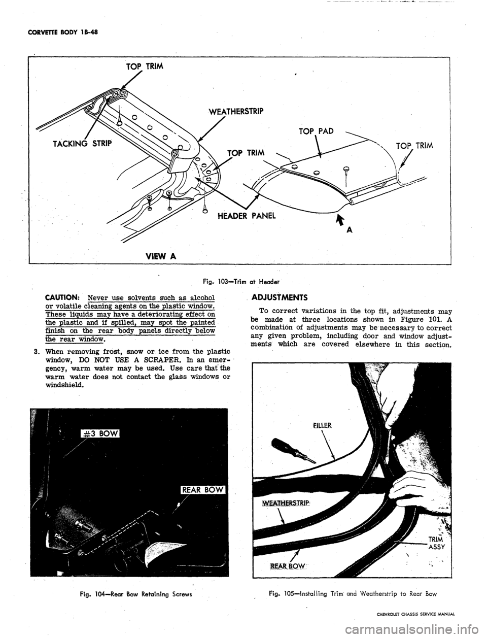
Fig.
103-Trim at Header
CAUTION: Never use solvents such as alcohol
or volatile cleaning agents on the plastic window.
These liquids may have a deteriorating effect on
the plastic and if spilled, may spot the painted
finish on the rear body panels directly below
the rear window.
3.
When removing frost, snow or ice from the plastic
window, DO NOT USE A SCRAPER. In an emer-
gency, warm water may be used. Use care that the
warm water does not contact the glass windows or
windshield.
ADJUSTMENTS
To correct variations in the top fit, adjustments may
be made at three locations shown in Figure 101. A
combination of adjustments may be necessary to correct
any given problem, including door and window adjust-
ments which are covered elsewhere in this section.
Fig. 104—Rear Bow Retaining Screws
Fig. 105—Installing Trim and Weatherstrip to Rear Bow
CHEVROLET CHASSIS SERVICE MANUAL
Page 156 of 659
CORVETTE BODY 1B-49
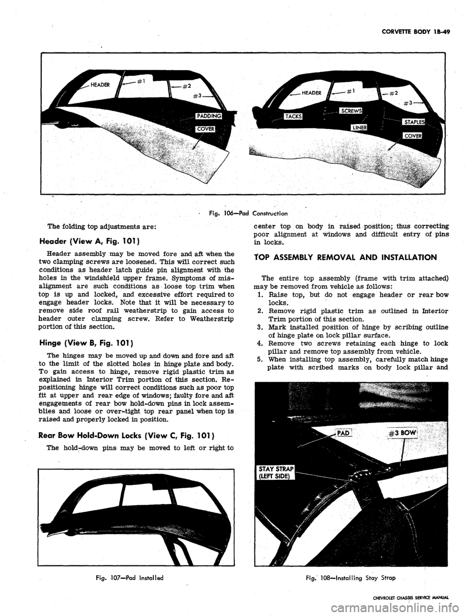
Fig.
106-—Pad Construction
The folding top adjustments are:
Header (View A, Fig. 101)
Header assembly may be moved fore and aft when the
two clamping screws are loosened. This will correct such
conditions as header latch guide pin alignment with the
holes in the windshield upper frame. Symptoms of mis-
alignment are such conditions as loose top trim when
top is up and locked, and excessive effort required to
engage header locks. Note that it will be necessary to
remove side roof rail weatherstrip to gain access to
header outer clamping screw. Refer to Weatherstrip
portion of this section.
Hinge (View B, Fig. 101)
The hinges may be moved up and down and fore and aft
to the limit of the slotted holes in hinge plate and body.
To gain access to hinge, remove rigid plastic trim as
explained in Interior Trim portion of this section. Re-
positioning hinge will correct conditions such as poor top
fit at upper and rear edge of windows; faulty fore and aft
engagements of rear bow hold-down pins in lock assem-
blies and loose or oversight top rear panel when top is
raised and properly locked in position.
Rear Bow Hold-Down Locks (View C, Fig. 101)
The hold-down pins may be moved to left or right to
center top on body in raised position; thus correcting
poor alignment at windows and difficult entry of pins
in locks.
TOP ASSEMBLY REMOVAL AND INSTALLATION
The entire top assembly (frame with trim attached)
may be removed from vehicle as follows:
1.
Raise top, but do not engage header or rear bow
locks.
2.
Remove rigid plastic trim as outlined in Interior
Trim portion of this section.
3.
Mark installed position of hinge by scribing outline
of hinge plate on lock pillar surface.
4.
Remove two screws retaining each hinge to lock
pillar and remove top assembly from vehicle.
5.
When installing top assembly, carefully match hinge
plate with scribed marks on body lock pillar and
Fig.
107-Pad Installed
Fig.
108—Installing Stay Strap
CHEVROLET CHASSIS SERVICE MANUAL
Page 157 of 659
CORVETTE BODY 1B-50
WIRE-ON
BINDING
EXCESS
MATERIAL!
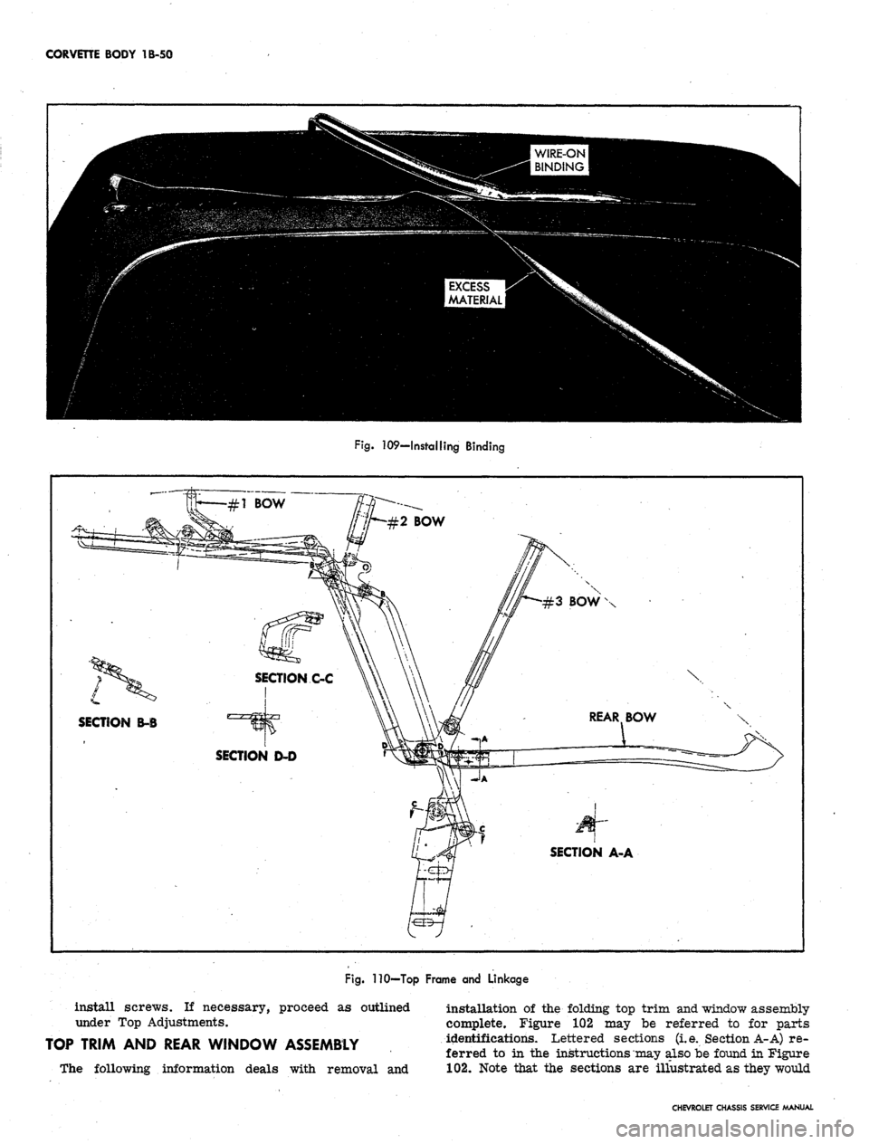
Fig.
109—Installing Binding
\
L
SECTION B-B
SECTION A-A
Fig.
110—Top Frame and Linkage
install screws. If necessary, proceed as outlined
under Top Adjustments.
TOP TRIM AND REAR WINDOW ASSEMBLY
The following information deals with removal and
installation of the folding top trim and window assembly
complete. Figure 102 may be referred to for parts
identifications. Lettered sections (i.e. Section A-A) re-
ferred to in the instructions may also be found in Figure
102.
Note that the sections are illustrated as they would
CHEVROLET CHASSIS SERVICE MANUAL
Page 158 of 659
CORVETTE BODY
1B-51
Fig.
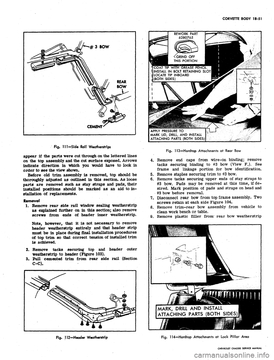
Ill-Side Rail Weatherstrips
appear
if the
parts were cut through on the lettered lines
on
the top
assembly and the
cut
surface exposed. Arrows
indicate direction
in
which
you
would have
to
look
in
order
to see
the view shown.
Before
old
trim assembly
is
removed,
top
should
be
thoroughly adjusted
as
outlined
in
this section.
As
loose
parts
are
removed such
as
stay -straps
and
pads, their
installed positions should
be
marked
as an aid to in-
stallation
of
replacements.
Removal
1.
Remove rear side rail window sealing weatherstrip
as explained further
on in
this section; also remove
screws from ends
of
header inner weatherstrip.
Note, however, that
it is not
necessary
to
remove
header weatherstrip entirely
and
that header strip
must
be- in
place during final installation procedures
of
top
trim
so
that correct tension
of
installed trim
is achieved.
2.
Remove tacks securing
top and
header outer
weatherstrip
to
header (Figure
103).
3.
Pull cemented trim from rear side rail (Section
C-C).
REWORK PART
6280765
^GRIND
OFF
THIS PORTION
COAT
TIP
WITH GREASE PENCIL.
II INSTALL
IN
BOLT RETAINING SLOT
LOCATE
TIP
INBOARD
(BOTH SIDES)
APPLY PRESSURE
TO
MARK
LID,
DRILL,
AND
INSTALL
ATTACHING PARTS (BOTH SIDES)
Fig.
113—Hardtop Attachments
at
Rear
Bow
4.
Remove end caps from wire-on binding; remove
tacks securing binding to #3 bow (View F.). See
frame and linkage portion for bow identification.
5.
Remove staples securing trim to #3 bow.
6. Remove tacks securing upper ends of stay straps to
#3 bow. Pads may be removed at this time, if de-
sired. Mark position of pads and straps on head and
#3 bow before removal.
7.
Disconnect rear bow from top frame assembly. Two
screws retain at each side Figure 104.
8. Remove trim-rear bow assembly from vehicle to
clean work bench or table.
9. Remove plastic filler from' rear bow weatherstrip
MARK, DRILL
AND
INSTALL
ATTACHING PARTS (BOTH SIDES)
Fig.
112-Header Weatherstrip
Fig.
114—Hardtop Attachments
at
Lock Pillar Area
CHEVROLET CHASSIS SERVICE MANUAL
Page 159 of 659
CORVETTE BODY 1B-52
and pull weatherstrip and trim from rear bow.
Section A-A shows installed position of these com-
ponents. Refer also to figure 105.
installation
1.
Find and mark center of header, #3 bow, rear bow
and leading and trailing edges of top trim. Align
these marks during installation and recheck their
alignment from time to time while installation is in
progress, especially during tacking or stapling.
2.
Assemble top trim and weatherstrip to rear bow,
referring to Section A-A and Figure 105. Note that
filler strip locks this assembly together and goes
in last. Align center marks.
3.
If new pads are required, install at this time, align-
ing with marks made when old pads were removed.
Figure 106 shows pad construction; Figure 107 shows
pad installed.
4.
Install top trim-rear bow assembly on top frame
with four screws removed at disassembly.
5.
Lock down rear bow in desired "top up" position.
Pull up stay straps and staple or tack to #3 bow
(fig. 108).
6. Pull leading edge of trim iip to header and align
center marks. Smooth out fabric and clamp, tack
or staple temporarily to header.
7.
Draw window extension up to #3 bow, aligning cen-
tering marks. Turn an ample amount of fabric under
and tack to #3 bow. Apply neoprene trim cement,
GM Part #3695016 or equivalent, to area shown in
View D of Figure 102. Follow directions on package.
8. Draw roof portion of trim over #3 bow, align marks
and tack on staple.
9. Trim off excess material and install wire-on binding
as shown in Figure 109 and View D of Figure 102.
Install binding caps.
10.
Remove temporary clamps or fastenings holding trim
to header.
11.
With header locked down, pull trim assembly up tight
and mark for final installation.
12.
Apply trim cement to header and rear side rail.
13.
Release header from windshield. Tack or staple trim
to header (fig. 103).
14.
Apply trim to rear side frame, previously cemented.
15.
Install weatherstrips which were removed at dis-
assembly and install retaining screws in header
weatherstrip.
16.
Make any adjustments necessary, following instruc-
tions listed under Folding Top—Adjustments.
FRAME AND LINKAGE
Figure 110 illustrates construction features of the
folding top frame and linkage. Various cross sections in
Figure 110 show the pivoting joints and their assembly.
If an operation is being performed which requires
removal of folding top trim, follow directions in this
section. The entire frame assembly may be removed and
replaced as a unit. Follow instructions for Folding Top
Trim and Rear Window Assembly and Top Assembly—
Removal and Installation.
The pivoting joints should be lubricated with light
machine oil once a year. Apply oil sparingly so as not
to stain top trim.
WEATHERSTRIP
Side Rail Weatherstrip
Figure 111 illustrates installation of side rail weather-
strip which acts to seal window opening. The weather-
strip is held in place by studs which are part of the
weatherstrip assembly, and by neoprene base cement
which is applied between weatherstrip and side rail
surface.
When replacing weatherstrip remove all rust, old
cement and foreign material from the surfaces to be
cemented, to assure successful bonding. Use only good
quality neoprene cement suitable for weatherstrip
application.
Header Weatherstrip
Weatherstrip assembly is retained to the header panel
by a combination of studs, sheet metal screws and special
fasteners as shown in Figure 112, along with neoprene
base weatherstrip cement.
Figure 99 shows' a cross section of weatherstrip taken
through a special fastener. To replace fastener, rotate
ninety degrees to align fastener head with slot. Follow
directions for cementing in the Side Rail Weatherstrip
instructions preceding this write up.
ADDING HARDTOP (ROOF PANEL ASSEMBLY)
An available roof panel assembly (hardtop) complete
can be added to convertible model Corvettes. The hard-
ware is included with the panel assembly.
Reworking of a plastic part (one for each side of the
roof panel) can be used as a marker for drilling of two
required holes in the folding top compartment lid* Hard-
ware is attached at four locations — two on the lid and
two (one each side) at the lock pillar area as follows:
1.
Rework two plastic retainers (#6280765) (used on
Chevrolet and Corvair door inner panels for trim
retention) as shown by Figure 113.
2.
Slide the reworked plastic retainers into the bolt re-
tainer slots on each side of the hardtop rear bow
(position plastic tip inboard).
3.
Mark the hardtop reveal molding at the approximate
location of the two plastic retainers,
4.
Mark the tips of the two plastic retainers with a
china marker pencil.
5.
Close the soft top compartment lid.
6. With aid of an ^assistant, position front of hardtop
onto header and lower onto vehicle. Do not fasten
latches at windshield header.
7.
Apply hand pressure at reveal molding marks.
8. Mark roof panel attachment hole location at each
lock pillar area (fig. 114).
9. With aid of an assistant, lift roof panel straight up
off body and set roof panel aside.
10.
Mark the drill position at the four china marks with
a center punch.
11.
Place a 2" x 4" board under the top compartment lid
to prevent drill damage to folding top material. Make
certain the compartment lid is securely locked
before drilling.
12.
Drill 1/8" pilot hole at the 4 marked locations.
CHEVROLET CHASSIS SERVICE MANUAL
Page 272 of 659
ENGINE 6-7
Tune Up should be checked whenever the Air Injection
Reactor System seems to be malfunctioning. Particular
care should be taken in checking items that affect fuel-air
ratio such as the crankcase ventilation system, the car-
buretor and the carburetor air cleaner. Carburetors and
distributors for engines with the Air Injection Reactor
System are designed, particularly, for these engines;
therefore, they must not be interchanged with or replaced
by a carburetor or distributor designed for an engine
without the Air Injection Reactor System.
Choke Adjustment (Fig. 11)
With Remote Choke
1.
Remove air cleaner and check to see that choke
valve and rod move freely.
2.
Disconnect choke r*od at choke lever.
Check choke adjustment as follows:
On all except 275 hp 327 cu. in. engines, hold
choke valve closed and pull rod up against stop. The
top of choke rod end should be 1/2 - 1 rod diameter
4.
5.
above top of hole in choke valve lever.
On 275 hp 327 cu. in. engines, hold choke valve
closed and push rod down against stop on thermostat
bracket. The top of the choke rod should be 1/2 - 1
rod diameter below the top of the hole in the choke
lever.
If necessary, adjust rod length by bending rod at off-
set. (Bend must be such that rod enters choke lever
hole freely and squarely.)
Connect rod at choke lever and install air cleaner.
3.
With Manual
Choke
1.
Remove air cleaner.
2.
Push hand choke knob in to within 1/8" of instrument
panel.
3.
Loosen choke cable at carburetor bracket and adjust
cable through the clip until the choke valve is wide
open.
4.
Tighten cable clamp at carburetor bracket and check
operation of choke valve to ensure full closed and
wide open positions.
INSTRUMENT CHECK-OUT
Instrument Hook Up
Connect vacuum gauge, dwell meter, tachometer and
timing light as recommended by the manufacturer of the
equipment being used.
Check and Adjust Dwell
1.
Start engine then ch^ck ignition dwell.
.2.
If dwell is not within specifications, adjust dwell as
follows:
V8 ENGINES
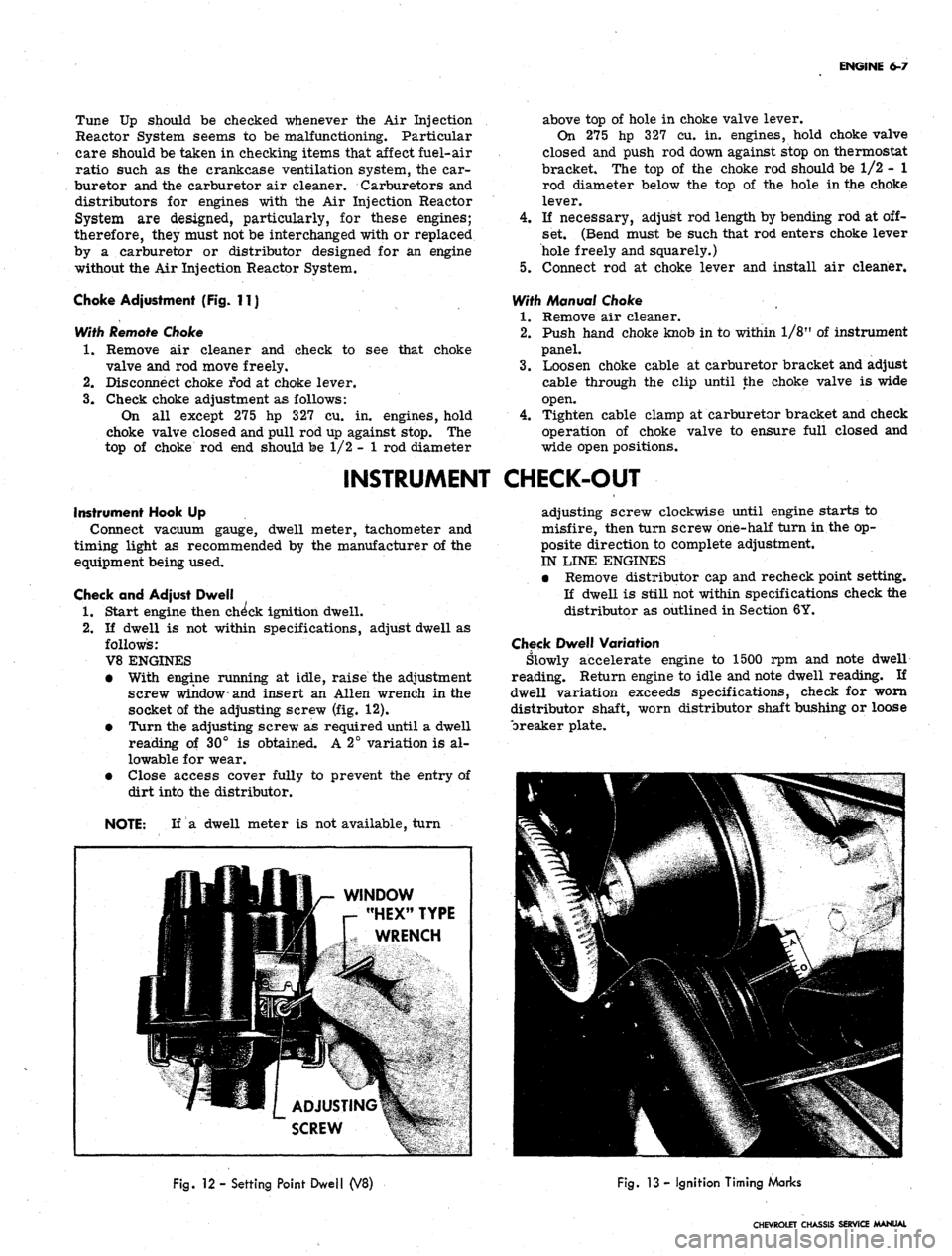
• With engine running at idle, raise the adjustment
screw window-and insert an Allen wrench in the
socket of the adjusting screw (fig. 12).
• Turn the adjusting screw as required until a dwell
reading of 30° is obtained. A 2° variation is al-
lowable for wear.
• Close access cover fully to prevent the entry of
dirt into the distributor.
NOTE: If a dwell meter is not available, turn
adjusting screw clockwise until engine starts to
misfire, then turn screw one-half turn in the op-
posite direction to complete adjustment.
IN LINE ENGINES
• Remove distributor cap and recheck point setting.
If dwell is still not within specifications check the
distributor as outlined in Section 6Y.
Check Dwell Variation
Slowly accelerate engine to 1500 rpm and note dwell
reading. Return engine to idle and note dwell reading. If
dwell variation exceeds specifications, check for worn
distributor shaft, worn distributor shaft bushing or loose
breaker plate.
WINDOW
"HEX" TYPE
WRENCH
Fig.
12 - Setting Point Dwell (V8)
Fig.
13 - Ignition Timing Marks
CHEVROLET CHASSIS SERVICE MANUAL
Page 347 of 659
ENGINE-ELECTRICAL 6Y-22
ADJUST DWELL
ANGLE SETTING OR
POINT OPENING
Fig.
lOi—Settihg Point Opening
To adjust the contact point opening:
1.
If necessary, align points (fig. 9i) by bending the
fixed contact support. Do not bend the breaker lever.
Do not attempt to align used points; replace them
where serious misalignment is observed. Use an
aligning tool if available.
2.
Turn or crank the distributor shaft until the breaker
arm rubbing block is on the high point of the cam
lobe.
This will provide maximum point opening.
3.
Loosen the contact support lock screw.
4.
Use a screw driver (fig. lOi) to move the point sup-
port to obtain a .019" opening for new points and a
.016"
opening for used points.
5.
Tighten the contact support lock screw and recheck
the point opening.
6. After checking and adjusting the contact point open-
ing to specifications, the cam angle or dwell should
be checked with a dwell angle meter if such equip-
ment is available (see Specifications for proper dwell
angle).
If the cam angle is less than the specified
minimum, check for defective or misaligned contact
points or worn distributor cam lobes. The variation
in cam angle readings between idle speed and 1750
engine rpm should not exceed 3°. Excessive varia-
tion in this speed range indicates wear- in the
distributor.
NOTE:
Cam angle readings taken at speeds
above 1750 engine rpm may prove unreliable
on some cam angle meters.
Eight Cylinder Engine Distributor
On the Vehicle
With the engine running at idle and operating tempera-
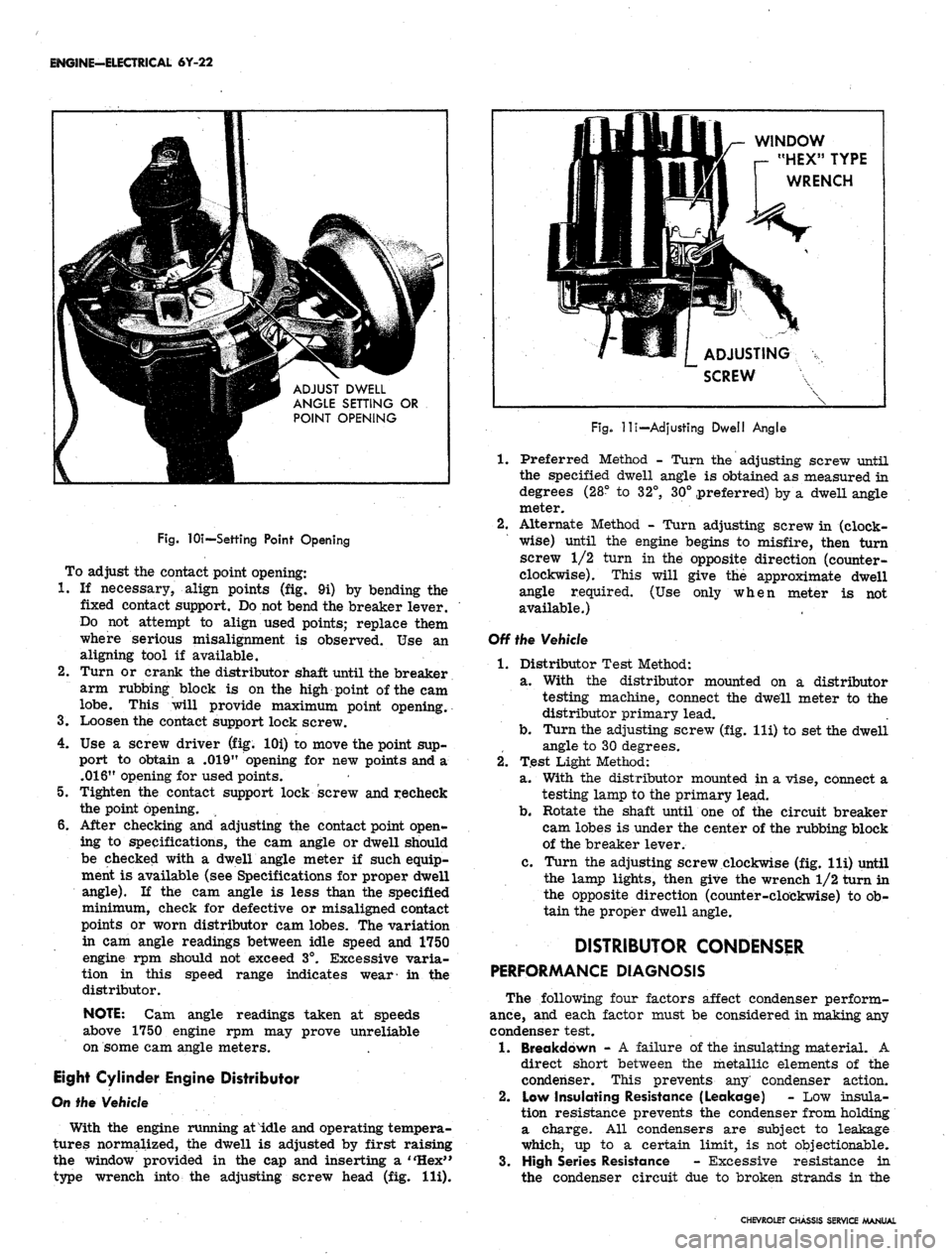
tures normalized, the dwell is adjusted by first raising
the window provided in the cap and inserting a "Hex"
type wrench into the adjusting screw head (fig. Hi).
WINDOW
r- "HEX" TYPE
WRENCH
ADJUSTING
SCREW
Fig.
-lli—Adjusting Dwell Angle
1.
Preferred Method - Turn the adjusting screw until
the specified dwell angle is obtained as measured in
degrees (28° to 32°, 30° preferred) by a dwell angle
meter.
2.
Alternate Method - Turn adjusting screw in (clock-
wise) until the engine begins to misfire, then turn
screw 1/2 turn in the opposite direction (counter-
clockwise). This will give the approximate dwell
angle required. (Use only when meter is not
available.)
Off the Vehicle
1.
Distributor Test Method:
a. With the distributor mounted on a distributor
testing machine, connect the dwell meter to the
distributor primary lead.
b.
Turn the adjusting screw (fig. lli) to set the dwell
angle to 30 degrees.
2.
Test Light Method:
a. With the distributor mounted in a vise, connect a
testing lamp to the primary lead.
b.
Rotate the shaft until one of the circuit breaker
cam lobes is under the center of the rubbing block
of the breaker lever.
c. Turn the adjusting screw clockwise (fig. lli) until
the lamp lights, then give the wrench 1/2 turn in
the opposite direction (counter-clockwise) to ob-
tain the proper dwell angle.
DISTRIBUTOR CONDENSER
PERFORMANCE DIAGNOSIS
The following four factors affect condenser perform-
ance,
and each factor must be considered in making any
condenser test.
1.
Breakdown - A failure of the insulating material. A
direct short between the metallic elements of the
condenser. This prevents any' condenser action.
2.
Low Insulating Resistance (Leakage) - Low insula-
tion resistance prevents the condenser from holding
a charge. All condensers are subject to leakage
which, up to a certain limit, is not objectionable.
3.
High Series Resistance - Excessive resistance in
the condenser circuit due to broken strands in the
CHEVROLET CHASSIS SERVICE MANUAL
Page 514 of 659
ELECTRICAL-BODY AND CHASSIS 12-2
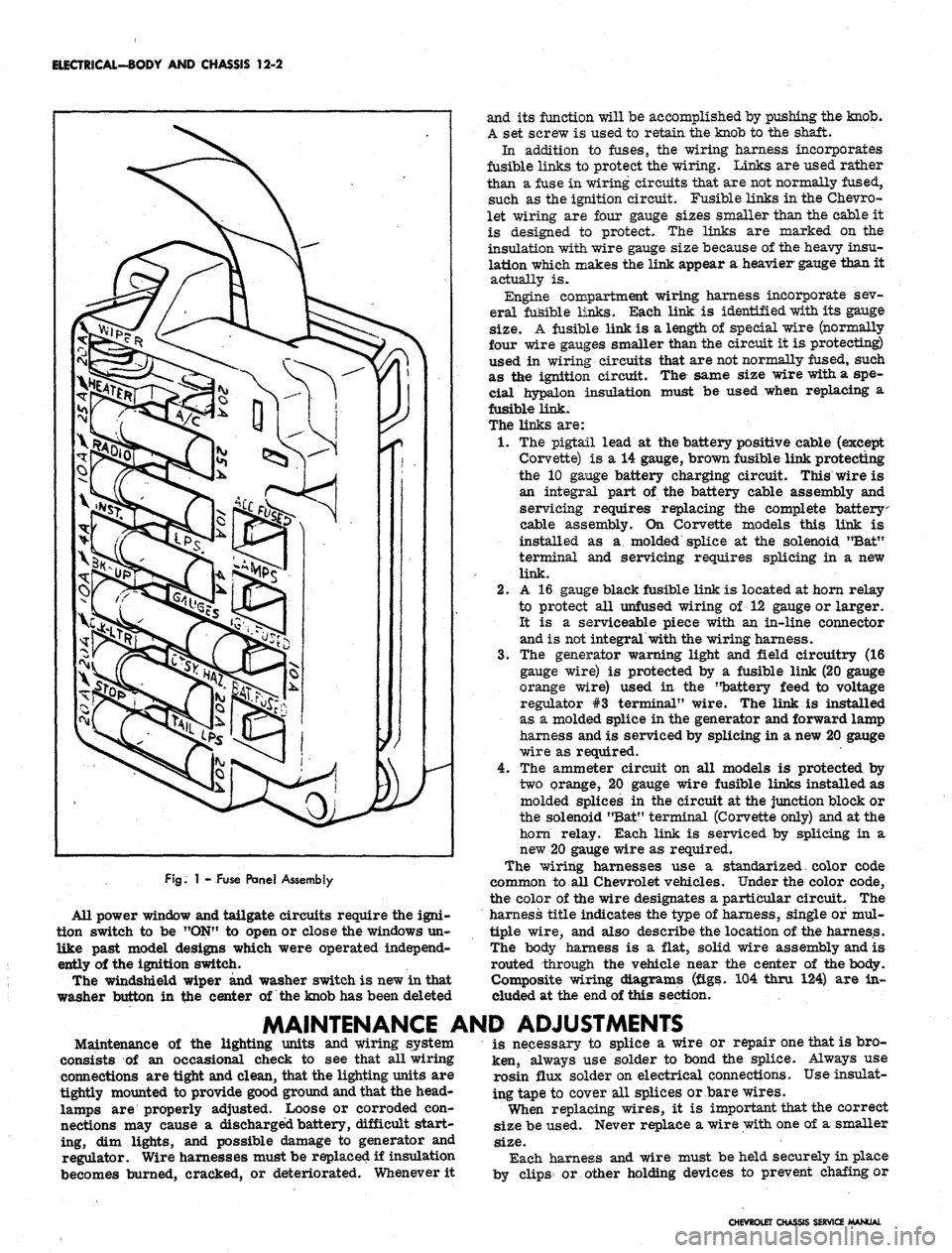
FJg.
1 - Fuse Panel Assembly
All power window and tailgate circuits require the igni-
tion switch to be "ON" to open or close the windows un-
like past model designs which were operated independ-
ently of the ignition switch.
The windshield wiper and washer switch is new in that
washer button in the center of the knob has been deleted
and its function will be accomplished by pushing the knob.
A set screw is used to retain the knob to the shaft.
In addition to fuses, the wiring harness incorporates
fusible links to protect the wiring. Links are used rather
than a fuse in wiring circuits that are not normally fused,
such as the ignition circuit. Fusible links in the Chevro-
let wiring are four gauge sizes smaller than the cable it
is designed to protect. The links are marked on the
insulation with wire gauge size because of the heavy insu-
lation which makes the link appear a heavier gauge than it
actually is.
Engine compartment wiring harness incorporate sev-
eral fusible links. Each link is identified with its gauge
size.
A fusible link is a length of special wire (normally
four wire gauges smaller than the circuit it is protecting)
used in wiring circuits that are not normally fused, such
as the ignition circuit. The same size wire with a spe-
cial hypalon insulation must be used when replacing a
fusible link.
The links are:
1.
The pigtail lead at the battery positive cable (except
Corvette) is a 14 gauge, brown fusible link protecting
the 10 gange battery charging circuit. This wire is
an integral part of the battery cable assembly and
servicing requires replacing the complete battery
cable assembly. On Corvette models this link is
installed as a molded splice at the solenoid "Bat"
terminal and servicing requires splicing in a new
link.
2.
A 16 gauge black fusible link is located at horn relay
to protect all unfused wiring of 12 gauge or larger.
It is a serviceable piece with an in-line connector
and is not integral with the wiring harness.
3.
The generator warning light and field circuitry (16
gauge wire) is protected by a fusible link (20 gauge
orange wire) used in the "battery feed to voltage
regulator #3 terminal" wire. The link is installed
as a molded splice in the generator and forward lamp
harness and is serviced by splicing in a new 20 gauge
wire as required.
4.
The ammeter circuit on all models is protected by
two orange, 20 gauge wire fusible links installed as
molded splices in the circuit at the junction block or
the solenoid "Bat" terminal (Corvette only) and at the
horn relay. Each link is serviced by splicing in a
new 20 gauge wire as required.
The wiring harnesses use a standarized. color code
common to all Chevrolet vehicles. Under the color code,
the color of the wire designates a particular circuit. The
harness title indicates the type of harness, single of mul-
tiple wire, and also describe the location of the harness.
The body harness is a flat, solid wire assembly and is
routed through the vehicle near the center of the body.
Composite wiring diagrams (figs. 104 thru 124) are in-
cluded at the end of this section.
MAINTENANCE AND ADJUSTMENTS
Maintenance of the lighting units and wiring system
consists of an occasional check to see that all wiring
connections are tight and clean, that the lighting units are
tightly mounted to provide good ground and that the head-
lamps are properly adjusted. Loose or corroded con-
nections may cause a discharged battery, difficult start-
ing, dim lights, and possible damage to generator and
regulator. Wire harnesses must be replaced if insulation
becomes burned, cracked, or deteriorated. Whenever it
is necessary to splice a wire or repair one that is bro-
ken, always use solder to bond the splice. Always use
rosin flux solder on electrical connections. Use insulat-
ing tape to cover all splices or bare wires.
When replacing wires, it is important that the correct
size be used. Never replace a wire with one of a smaller
size.
Each harness and wire must be held securely in place
by clips or other holding devices to prevent chafing or
CHEVROLET CHASSIS SERVICE MANUAL
Page 516 of 659
ELECTRICAL-BODY AND CHASSIS 12-4
b.
hand lamp until the string is positioned over the
crossarm centerline. Turn the screw clockwise
in making the final adjustment to take up play in
the headlamp mechanism.
Repeat the above procedure on the right-hand
lamp to complete the horizontal adjustment of the
headlamps.
VERTICAL ADJUSTMENT
8. a. Numeral "2" (fig. 5) should appear in the "down"
window of each aimer. If not, loosen knob at
underside of aimer arm and slide back and forth
until the numeral does appear.
NOTE:
This setting will give a 2" drop of the
headlamp high beam spot centerline on a screen
placed 25 feet forward of the vehicle. Check
state laws for proper vertical setting.
b.
Turn headlamp vertical aim screw (fig. 5) on left-
hand unit counter-clockwise until the bubble is at
the inner end of the glass tube. Then turn screw
clockwise until bubble is centered in tube.
c. Repeat this procedure on right-hand headlamp
unit to complete vertical adjustment of lamps.
9. Recheck the string at the ends of each crossarm for
correct setting and the bubble on each aimer for
centered position.
10.
Remove the aimers by pulling on the suction cup tabs
through the openings in the aimers (fig. 6).
11.
With headlamps properly aimed, replace headlamp
bezels.
HOW TO SELECT A LEVEL AIMING AREA
1.
Select area you believe to be level.
2.
Remove headlamp bezels and install Aimers on each
headlamp (fig. 3) making sure aiming lugs engage
smoooth inner ring of the Aimer.
"
To install Aimer,
press firmly on the knob extending out from the cen-
ter of the Aimer base. This forces the suction cup
into place on the Sealed Beam unit.:
3.
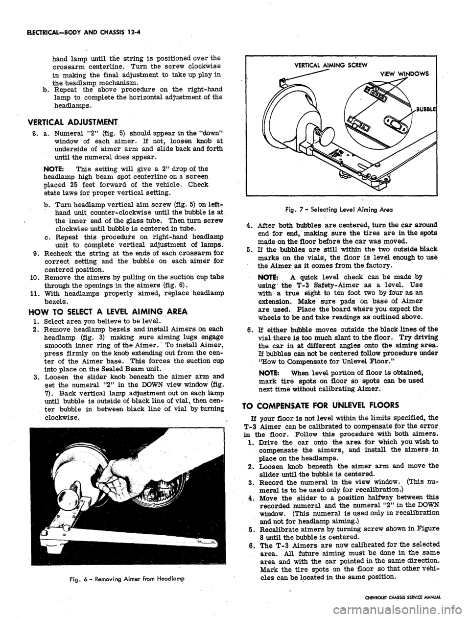
Loosen the slider knob beneath the aimer arm and
set the numeral "2" in the DOWN view window (fig.
7).
Back vertical lamp adjustment out on each lamp
until bubble is outside of black line of vial, then cen-
ter bubble in between black line of vial by turning
clockwise.
VERTICAL AIMING SCREW
VIEW WINDOWS
BUBBLE
Fig.
6 - Removing Aimer from Headlamp
Fog.
7- Selecting Level Aiming Area
4.
After botli bubbles are centered, turn the car around
end for end, making sure the tires are in the spots
made on the floor before the car was moved.
.5.
If the bubbles are still within the two outside black
marks on the vials, the floor is level enough to use
the Aimer as it comes from the factory.
NOTE:
A quick level check can be made by
using the T-3 Safety-Aimer as a level. Use
with a true eight to ten foot two by four as an
extension. Make sure pads on base of Aimer
are used. Place the board where you expect the
wheels to be and take readings as outlined above.
6. If either bubble moves outside the black lines of the
vial there is too much slant to the floor. Try driving
the car in at different angles onto the aiming area.
If bubbles can
not
be centered follow procedure under
"How to Compensate for Unlevel Floor."
NOTE:
When level portion of floor is obtained,
mark tire spots on floor so spots can be used
next time without calibrating Aimer.
TO COMPENSATE FOR UNLEVEL FLOORS
If your floor is not level within the limits specified, the
T-3 Aimer can be calibrated to compensate for the error
in the floor. Follow this procedure with both aimers.
1.
Drive the car onto the area for which you wish to
compensate the aimers, and install the aimers in
place on the headlamps.
2.
Loosen knob beneath the aimer arm and move the
slider until the bubble is centered.
3.
Record the numeral in the view window. (This nu-
meral is to be used only for recalibration.)
4.
Move the slider to a position halfway between this
recorded numeral and the numeral "2" in the
DOWN
window. (This numeral is used only in recalibration
and not for headlamp aiming.)
5.
Recalibrate aimers by turning screw shown in Figure
8 until the bubble is centered.
6. The T-3 Aimers are now calibrated for the selected
area. All future aiming must be done in the same
area and with the car pointed in the same direction.
Mark the tire spots on the floor so that other vehi-
cles can be located in the same position.
CHEVROLET CHASSIS SERVICE MANUAL