ECU CHEVROLET CAMARO 1967 1.G Chassis Workshop Manual
[x] Cancel search | Manufacturer: CHEVROLET, Model Year: 1967, Model line: CAMARO, Model: CHEVROLET CAMARO 1967 1.GPages: 659, PDF Size: 114.24 MB
Page 605 of 659
BUMPERS 14-4
tighten any bolts until all bolts have been installed.
Installation
1.
Position bumper bracket and brace on the frame
aligning holes in frame with those in bracket and
brace.
2.
Loosely install bolts, lock washers and nuts. Note
that eight sided adjustment washers (fig. 4) are
placed at the inside surface of each rear frame
channel. Dial washers as required to position
bumper at correct height.
Tighten all mounting bolts securely, connect back-up
lamp and license plate lamp wiring, and lower rear
of vehicle.
GENERAL DESCRIPTION-CHEVY II
The front and rear bumpers are of a one piece design
with the parking and turn signal assemblies attached to
each outboard end of the front bumper.
SERVICE OPERATIONS
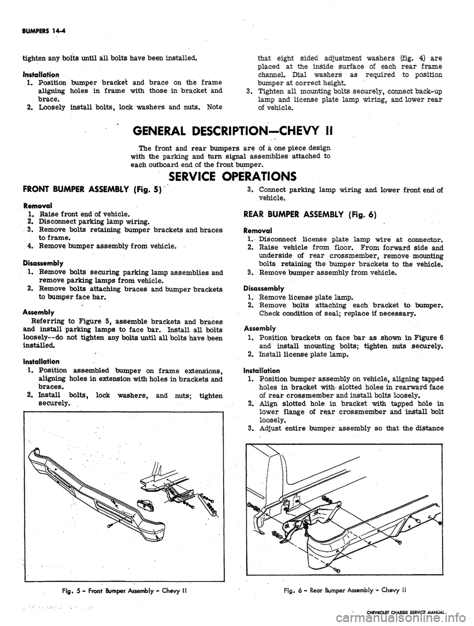
FRONT BUMPER ASSEMBLY (Fig. 5)
Removal
1.
Raise front end of vehicle.
2.
Disconnect parking lamp wiring.
3.
Remove bolts retaining bumper brackets and braces
to frame.
4.
Remove bumper assembly from vehicle.
Disassembly
1.
Remove bolts securing parking lamp assemblies and
remove parking lamps from vehicle.
2.
Remove bolts attaching braces and bumper brackets
to bumper face bar.
Assembly
Referring to Figure 5, assemble brackets and braces
and install parking lamps to face bar. Install all bolts
loosely—do not tighten any bolts until all bolts have been
installed.
Installation
1.
Position assembled bumper on frame extensions,
aligning holes in extension with holes in brackets and
braces.
2.
Install bolts, lock washers, and nuts; tighten
securely.
3.
Connect parking lamp wiring and lower front end of
vehicle.
REAR BUMPER ASSEMBLY (Fig. 6)
Removal
1.
Disconnect license plate lamp wire at connector.
2.
Raise vehicle from floor. From forward side and
underside of rear crossmember, remove mounting
bolts retaining the bumper brackets to the vehicle.
3.
Remove bumper assembly from vehicle.
Disassembly
1.
Remove license plate lamp.
2.
Remove, bolts attaching each bracket to bumper.
Check condition of seal; replace if necessary.
Assembly
1.
Position brackets on face bar as shown in Figure 6
and install mounting bolts; tighten nuts securely.
2.
Install license plate lamp.
Instalfation
1.
Position bumper assembly on vehicle, aligning tapped
holes in bracket with- slotted holes in rearward face
of rear crossmember and install bolts loosely.
2.
Align slotted hole in bracket with tapped hole in
lower flange of rear crossmember and install bolt
loosely.
3.
Adjust entire bumper assembly so that the distance
Fig.
5 - Front Bumper Assembly - Chevy
Fig.
6 - Rear Bumper Assembly - Chevy
CHEVROLET CHASSIS SERVICE MANUAL
Page 608 of 659

BUMPERS 14-7
only and the distance between inner upper brace and
frame filled in with shims. Bolts may then be installed
to secure brace to frame.
REAR LICENSE PLATE HOUSING
The rear license plate housing may be removed from
the vehicle by removing the license plate and removing
the retaining screws as shown in Figure 9.
Fig.
9- Rear License Plate Housing
GENERAL DESCRIPTION-CAMARO
The Camaro front and rear bumpers are of a single
piece wrap around design. The front license plate bracket
functions as a bumper support between the valance panel
and bumper. Holes in the underside of bumpers, slightly
inboard of lower bumper bracket bolt, provide for new
jack load rest stud for jacking purposes.
SERVICE OPERATIONS
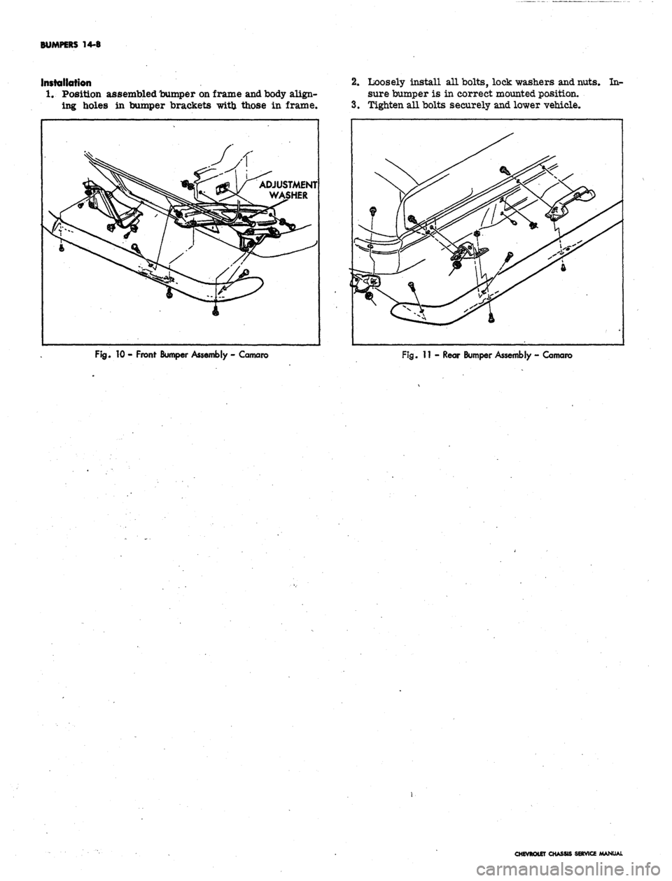
FRONT BUMPER ASSEMBLY (Fig. 10)
Removal
1.
Raise and support front end of vehicle.
2.
Remove bolts securing bumper support brackets to
frame.
3.
Remove bolts, one on each side at fender extension
panels, securing bumper to outer bumper bracket.
4.
Remove screws and nuts securing license plate
bracket to valance panel and remove bumper from
vehicle.
Disassembly
1.
Remove bolts attaching two support brackets to
bumper.
2.
Remove screw and nut securing license plate bracket
to bumper.
Assembly
Assemble the front bumper following the disassembly
procedure in reverse order. Install all bolts loosely; do
not tighten any bolts until all bolts are installed.
Installation
1.
Position assembled bumper on frame horns aligning
holes in bumper brackets with those in frame.
2.
Loosely install bolts, lock washers, and nuts. .Note
3.
the eight sided adjustment washers (fig. 10) are
placed in the tab of each bumper bracket. Dial the
adjustment washers in the tabs as required to posi-
tion the bumper at the correct mounted height.
Tighten all bolts securely and lower vehicle.
REAR BUMPER ASSEMBLY (Fig. 11)
Removal
1.
Raise and support rear end of vehicle.
2.
Remove bolts securing bumper brackets to frame
and rear fenders.
3.
Remove screws securing license plate bracket to
body and remove bumper from vehicle.
Disassembly
1.
Remove bolts securing four support brackets to
bumper.
2.
Remove rivets securing license plate bracket to
bumper.
Assembly
Assemble the rear bumper following the disassembly
procedure in reverse order. Install all bolts loosely; do
not tighten any bolts until all bolts are installed.
CHEVROLET CHASSIS SERVICE MANUAL
Page 609 of 659
BUMPERS 14-8
Ifistaliotion
1.
Position assembled bumper on frame and body align-
ing holes in bumper brackets with those in frame.
2.
Loosely install all bolts, lock washers and nuts. In-
sure bumper is in correct mounted position.
3.
Tighten all bolts securely and lower vehicle.
Fig.
10 - Front Bumper Assembly - Camaro
Fig.
11 - Rear Bumper Assembly - Camaro
CHEVROLET CHASSIS SERVICE MANUAL
Page 622 of 659
ACCESSORIES 15-13
SYSTEM TEST
CHECKS AND ADJUSTMENTS
Automatic Level Control Test Gauge (Fig. 15)
A complete system test includes on and off-the-car
component tests.. '
On the car tests are:
Quick check of Automatic Level Control System
Compressor output test
Regulator test and adjustment
Control valve test
Time delay test
Line and fitting leak test
Trim adjustment
Off-the-car operations include:
Control valve replacement
Compressor repair
Component leak tests
a. Compressor, reservoir, and regulator
b.
Control valve
c. Superlifts
Quick Check-On Car (Reservoir Pressure at 150 PSI)
1.
Fill the fuel tank or simulate at the rate of 6 lbs./
gal.
- otherwise car should be empty.
2.
Turn engine off.
3.
Add a 2 passenger load to the rear bumper or tail-
gate.
Maintain the load until the -car lifts or AT
LEAST 20 SECONDS.
4.
After car lifts remove the load and observe until the
car lowers.
FILL VALVE
J-21999
CONNECTORS
Fig.
15 - Test Gauge Set J-22124
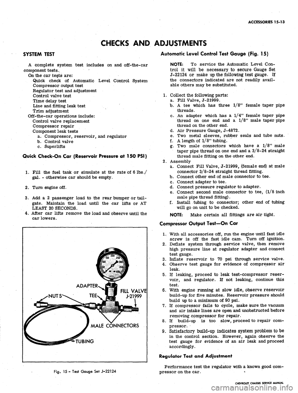
NOTE: To service the Automatic Level Con-
trol it will be necessary to secure Gauge Set
J-22124 or make up the following test gauge. If
the connectors indicated are not readily avail-
able others may be substituted.
1.
Collect the following parts:
a. Fill Valve, J-21999.
b.
A tee which has three 1/8M female taper pipe
threads.
c. An adapter which has a 1/4" female taper pipe
thread on one end and a 1/8" male taper pipe
thread on the other end.
d. Air Pressure Gauge, J-4872.
e. Two metal sleeves, rubber seals and tube nuts.
f. A length of 1/8" tubing. ~
g. Two male connectors which have a 1/8" male
taper pipe thread on one end and a 3/8-24 straight
thread male fitting on the other end.
2.
Assembly
a. Connect Fill Valve, J-21999, (female end) at male
connector 3/8-24 straight thread fitting.
b.
Connect other end of male connector to tee.
c. Connect adapter to tee.
d. Connect pressure regulator to adapter.
e. Connect second male connector to tee, (1/8 inch
male pipe thread fitting).
f. Install tubing to connector; other end of tubing
will go on unit to be checked.
NOTE:
Make certain all fittings are air tight.
Compressor Output Test—On Car
1.
With all accessories off, run the engine until fast idle
screw is off the fast idle cam. Turn off ignition.
2.
Deflate system through service valve, then remove
high pressure line at regulator adapter and connect
test gauge.
3.
Inflate reservoir to 70 psi through service valve.
4.
Observe test gauge for evidence of compressor air
leak.
5.
If leaking, proceed to leak test-compressor reser-
voir, and regulator. If not leaking, continue this
test.
6. With engine running at slow idle, observe reservoir
build-up for five minutes. Reservoir pressure should
build up to a minimum of 90 psi.
7.
If compressor fails to cycle, make sure the vacuum
and air intake lines are open and unobstructed before
removing compressor for repair.
8. If build-up is too slow, proceed to repair com-
pressor.
9. Satisfactory build-up indicates system problem to be
in the control section. However, again observe the
test gauge for evidence of an air leak and proceed
accordingly.
Regulator Test and Adjustment
Performance test the regulator with a known good com-
pressor on the car. *
CHEVROLET CHASSIS SERVICE MANUAL
Page 624 of 659
ACCESSORIES 15-15
Control Valve
1.
Remove control valve unit from car.
2.
Clean exterior of control valve thoroughly.
3.
Connect test gauge and air pressure source to intake
adapter and open air pressure (80-110 psi).
4.
Submerge unit in water. No air should escape if
overtravel lever is in "neutral" position. If bubbles
escape from Superlift port, replace control valve.
5. Shut, off air pressure and detach test gauge from air
intake port. Plug intake port with Fill Valve,
J-21999 (female end).
6. Connect test gauge to Superlift port and open air
pressure.
7. With overtravel lever in "neutral" position no air
should escape. If bubbles escape from exhaust port,
replace control valve.
8. If air escapes around edge of cover plate, tighten
screws on replace gasket.
9. R(emove control valve from water. Actuate over-
travel lever to expel any water from unit.
10.
Sjiut off air pressure and remove line from Superlift
[
Lines and Fittings
1.
Eisconnect overtravel lever from link.
2.
Bold lever up in intake position for maximum Super-
lift inflation and release.
3.
iieak check all connections with a soap and water
splution.
[.
Superlifts
1.
disconnect lines and remove unit from car.
2.
ijiflate individually to 50-60 psi utilizing Fill Valves
jt-21999. Submerge in water and observe unit for
leaks.
3.
Install Superlifts.
SERVICE OPERATIONS
CONTROL VALVE
Removal
1.
Deflate system using service valve.
2.
Disconnect two air lines at leveling valve intake and
Superlift ports.
3.
Disconnect link from overtravel lever by removing
one nut and lock washer.
4.
Remove two screws securing leveling valve to frame
and remove leveling valve.
Installation
1.
Install control valve with two screws, with time delay
mechanism down.
2.
Secure link to overtravel lever with one nut and lock
washer. On all station wagons s'eries the link is se-
cured to the lower hole. On all other series cars
with standard springs, the link is secured to the up-
per hole.
3.
Connect air lines at control valve intake and Super-
lift port.
4.
Inflate reservoir to 140 psi or maximum pressure
available through service valve.
COMPRESSOR, RESERVOIR AND REGULATOR
Removal and Installation
1.
Disconnect air lines (manifold and air cleaner) at
compressor end;
2.
Disconnect pressure line at compressor head.
3.
From wheel side of fender skirt, remove two screws
from bracket on compressor end.
4.
Remove nut and washer from reservoir stud at
bracket and remove assembly from vehicle.
5. Remove compressor end mount bracket.
6. Reverse Steps 1-5 for installation, then leak check
fittings.
COMPRESSOR, RESERVOIR AND REGULATOR
Disassembly Into Major Components (Fig. 17)
The compressor is a precision-built mechanism. All
parts should be carefully handled and assembled. Take
care to prevent entrance of dirt or foreign matter. DO
NOT LUBRICATE as unit is designed to run dry.
1.
Remove compressor as described above.
2.
Remove three flexible mounts and three adapters.
3.
Remove reservoir retaining through bolt, cover re-
taining screw and cover gasket that secure cover and
gasket to first stage housing. Remove cover and
discard gaskets.
4.
Remove two regulator retaining screws, regulator
assembly and O-ring from second stage housing.
Discard O-ring.
5/ Remove three nuts at reservoir flange and two
through bolts that enter from flanged side of res-
ervoir. Separate reservoir and O-ring. Discard
O-ring.
6. Remove three compressor retaining through bolts
that secure second stage housing to first stage
housing.
7. Slide second stage (small diameter) housing straight
off piston.
8. Disconnect arm tension spring from swivel arm.
9. Remove arm pivot screw and actuating arm.
10.
Slide piston assembly straight out of first stage
housing.
Disassembly, Inspection and Assembly of Major
Components (Fig. 17)
Diaphragm
1.
Inspect diaphragm for holes, looseness or other de-
fects and replace if necessary.
2.
Remove diaphragm retainer with diagonal pliers and
discard.
3.
Remove diaphragm plate, diaphragm, second dia-
phragm plate and corprene washer from piston.
4.
Install new corprene washed, old plate, new dia-
phragm with outer lip toward second stage side,
(fig. 17) and second plate. Plates should be installed
so that lip on each plate faces away from diaphragm.
5. Use a 13/16 inch deep socket as a pilot for the new
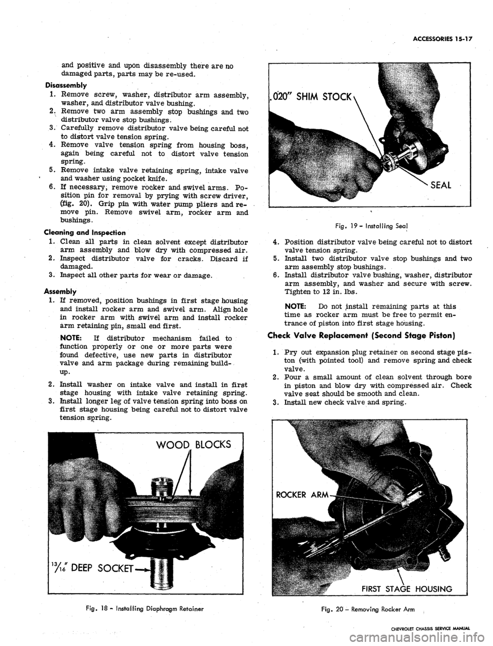
diaphragm retainer. Press against the piston shoul-
der on first stage side, (fig. 18) to position dia-
phragm retainer. The wood blocks used in the illus-
tration are each 3/4" x 3/4" x 12".
CHEVROLET CHASSIS SERVICE MANUAL
Page 625 of 659
ACCESSORIES 15-16
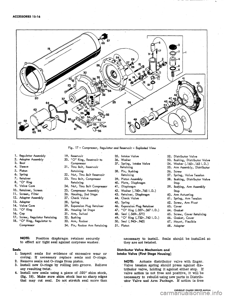
Fig.
17 - Compressor, Regulator and Reservoir - Exploded View
1.
Regulator Assembly
2.
Adapter Assembly
3. Boot
4.
Sleeve
5. Piston
6. Spring
7. Retainer
8. "O" Ring
9. Valve Core
10..
Retainer, Screen
11.
Screen, Filter
12.
Adapter Assembly
13.
Adapter
14.
Valve Core
15.
"O" Ring
16..
Cap
17.
Screw, Regulator Retaining
18.
"O" Ring, Regulator to
Compressor
19.
Reservoir
20.
"O" Ring, Reservoir to
Compressor
21.
Thru Bolt, Reservoir
Retaining
22.,
Nut, Thru .Bolt Reservoir
23.
Thru Bolt, Compressor
Retaining
24.
Nut, Thru Bolt Compressor
25.
Compressor Assembly
26.
Housing, 2nd Stage
27.
Check Valve
28.
Spring
29.
Expansion Plug Retainer
30.
Housing 1st Stage
31.
Arm, Swivel
32.
Bushing
33.
Arm, Rocker .
34.
Pin, Rocker Arm Retaining
35.
Intake Valve
36,
Washer
37.
Spring, Intake Valve
Retaining
38.
Pin, Bushing
Retaining
39.
Piston Assembly
40.
Plate, Diaphragm
41.
Diaphragm
42.
Washer (.760-.765 I.D.)
43.
Retainer, Diaphragm
44.
Check Valve
45.
Spring
46.
Expansion Plug Retainer
47.
"O" Ring (.357-.367 I.D.)
48.
Seal (.569-.571)
49.
"O" Ring (.732-.742 I.D.)
50.
Seal (.943-.945)
51.
Piston
52.
Distributor Valve
53.
Bushing, Distributor Valve
54.
Washer (.160-. 163 I.D.)
55. Arm Assembly, Distributor
56. Screw
57. Spring, Valve Tension
58.
Bushing, Distributor Valve
Stop
59. Bussing, Arm Assembly
Stop
60.
Arm Actuating
61.
Spring, Arm Tension
62.
Screw, Arm Pivot
63.
Cover
64.
Gasket
65. Screw, Cover Retaining
66. Gasket, Cover
67. Mount, Flexible
68.
Adapter
NOTE: Position diaphragm retainer securely
to effect air tight seal against corprene washer.
Seals
1.
Inspect seals for evidence of excessive wear or
coring. If necessary replace seals and O-rings.
2.
Remove seals and O-rings from piston.
3.
Install new O-rings by rolling into groove. Relieve
any resulting twist.
4.
Install new seals using a piece of .020" shim stock,
(fig. 19). Make sure shim stock has no sharp edges
that may cut seal. Do not stretch seal more than
necessary to install. Seals should be installed so
they are not twisted.
Distributor Valve Mechanism and
Intake Valve (First Stage Housing)
NOTE: Actuate distributor valve with finger.
' Valve tension spring should press against dis-
tributor valve, holding it against either stop. If
valve action is not free and positive, it will be
necessary to rebuild using new parts in Distrib-
utor Valve and Arm Package. If action is free
CHEVROLET CHASSIS SERVICE MANUAL
Page 626 of 659
ACCESSORIES 15-17
and positive and upon disassembly there are no
damaged parts, parts may be re-used.
Disassembly
1.
Remove screw, washer, distributor arm assembly,
washer, and distributor valve bushing.
2.
Remove two arm assembly stop bushings and two
distributor valve stop bushings.
3.
Carefully remove distributor valve being careful not
to distort valve tension spring.
4.
Remove valve tension spring from housing boss,
again being careful not to distort valve tension
spring.
5.
Remove intake valve retaining spring, intake valve
and washer using pocket knife.
6. If necessary, remove rocker and swivel arms. Po-
sition pin for removal by prying with screw driver,
(fig. 20). Grip pin with water pump pliers and re-
move pin. Remove swivel arm, rocker arm and
bushings.
Cleaning and Inspection
1.
Clean all parts in clean solvent except distributor
arm assembly and blow dry with compressed air.
2.
Inspect distributor valve for cracks. Discard if
damaged.
3.
Inspect all other parts for wear or damage.
Assembly
1.
If removed, position bushings in first stage housing
and install rocker arm and swivel arm. Align hole
in rocker arm with swivel arm and install rocker
arm retaining pin, small end first.
NOTE: If distributor mechanism failed to
function properly or one or more parts were
found defective, use new parts in distributor
valve and arm package during remaining build-
up.
2.
Install washer on intake valve and install in first
stage housing with intake valve retaining spring.
3.
Install longer leg of valve tension spring into boss on
first stage housing being careful not to distort valve
tension spring.
020"
SHIM STOCK
SEAL
Fig.
19- Installing Seal
4.
Position distributor valve being careful not to distort
valve tension spring.
5.
Install two distributor valve stop bushings and two
arm assembly stop bushings.
6. Install distributor valve bushing, washer, distributor
arm assembly, and washer and secure with screw.
Tighten to 12 in. lbs.
NOTE: Do not install remaining parts at this
time as rocker arm must be free to permit en-
trance of piston into first stage housing.
Check Valve Replacement (Second Stage Piston)
1.
Pry out expansion plug retainer on second stage pis-
ton (with pointed tool) and remove spring and check
valve.
2.
Pour a small amount of clean solvent through bore
in piston and blow dry with compressed air. Check
valve seat should be smooth and clean.
3.
Install new check valve and spring.
%/DEEP SOCKET
ROCKER /
WHgggb
I
^RM-j|
111511
FIRST
m
H
STAGE
1 Mill IMW •
W
HOUSING
Fig.
18- Installing Diaphragm Retainer
Fig.
20 - Removing Rocker Arm ,
CHEVROLET CHASSIS SERVICE MANUAL
Page 627 of 659
ACCESSORIES 15-18
4.
Insert new expansion plug retainer and tap in until it
bottoms.
Check Valve Replacement
(Second Stage Housing)
1.
Pry out expansion plug retainer on second stage
housing (with pointed tool) and remove spring and
check valve.
2.
Glean second stage housing with clean solvent and
blow dry with compressed air. Check valve seat
should be clean and smooth.
3.
Install new check valve and spring.
4.
Insert new expansion plug retainer and tap in until
it bottoms.
COMPRESSOR, RESERVOIR AND REGULATOR
Assembly From Major Components
1.
Slide piston assembly straight into first stage (large
diameter) housing.
2.
Install actuating arm and secure to first stage
housing with arm pivot screw, tightening to 12 in.
: lbs. ;
3.
Connect arm tension spring to swivel arm.
9.
10.
Rotate piston in first stage housing to align elongated
hole in diaphragm with vent port in first stage
housing.
Install three compressor retaining through bolts that
secure second stage housing to first stage housing.
Housings will align one way only. Nuts are posi-
tioned in counterbores in second stage housing.
Tighten to 28 in. lbs.
Install new O-ring on second stage housing. Wash
inside of reservoir in clean solvent and blow dry
with compressed" air. Install reservoir on second
stage housing with three nuts, tightening to 28 in. lbs.
Install two reservoir retaining through bolts, tighten-
ing to 28 in. lbs. Through, bolt heads should-be posi-
tioned against reservoir. Leave out through bolt that
secures cover.
Install new O-ring on regulator and secure regulator
with two regulator retaining screws, tighten to 35 in.
lbs.
Service valve should be on same side as first
stage housing.
Install new gasket, cover, and secure with cover
retaining screw and new cover gasket. Tighten cover
retaining screw to 35 in. lbs. Install through bolt
so head is positioned against reservoir. Tighten
through bolt to 28 in. lbs.
Install three adapters and flexible mounts.
Proceed to compressor output test on car.
CHEVROLET CHASSIS SERVICE MANUAL