air bleeding CHEVROLET CAMARO 1967 1.G Chassis Workshop Manual
[x] Cancel search | Manufacturer: CHEVROLET, Model Year: 1967, Model line: CAMARO, Model: CHEVROLET CAMARO 1967 1.GPages: 659, PDF Size: 114.24 MB
Page 234 of 659
BRAKES
SECTION 5
CONTENTS OF THIS SECTION
Duo Servo Brakes
Disc Brakes
Page
5-1 Power Brakes
5-24 Special Tools
Page
5-31
5-32
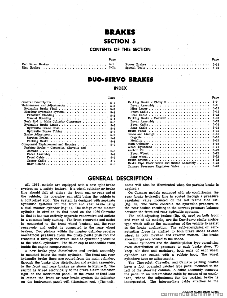
DUO-SERVO BRAKES
INDEX
Page
General Description 5-1
Maintenance and Adjustments 5-3
Hydraulic Brake Fluid .. . 5-3
Bleeding Hydraulic System 5-3
Pressure Bleeding 5-3
Manual Bleeding 5_4
Push Rod to Main Cylinder Clearance 5-5
Hydraulic Brake Lines 5-5
Hydraulic Brake Hose 5-5
Hydraulic Brake Tubing 5-6
Brake Adjustment. .................... 5-7
Service Brake 5-7
Parking Brake 5-8
Component Replacement and Repairs 5-9
Parking Brake - Chevrolet, Chevelle and
Camaro 5^9
Pedal Assembly 5-9
Front Cable ,. . . 5-9
Center Cable 5-9
Rear Cables. . 5-9
Parking Brake - Chevy n 5-9
Lever Assembly 5-9
Idler Lever 5-11
Front Cable 5-11
Rear Cable . . ; 5-12
Parking Brake - Corvette 5-13
Lever Assembly . . . . 5-13
Front Cable 5-14
Rear Cable . . 5-14
Brake Pedal 5-15
Shoes and Linings 5-16
Organic 5-16
Metallic 5-17
Main Cylinder 5-18
Wheel Cylinders 5-21
Anchor Pin 5-22
Front Wheel 5-22
Rear Wheel 5-22
Brake Drums • 5-22
Brake Pipe Distribution and Switch Assembly . . . . . 5-23
Camaro Pressure Regulator Valve 5-23
GENERAL DESCRIPTION
All 1967 models are equipped with a new split brake
system as a safety feature. If a wheel cylinder or brake
line should fail at either the front end or rear end of
the vehicle, the operator can still bring the vehicle to
a controlled stop. The system is designed with separate
hydraulic systems for the front and rear brake using
a dual master cylinder (fig. 1). The design of the master
cylinder is similar to that used on the 1966 Corvette
in that it has two entirely separate reservoirs and outlets
in a common body casting. The front reservoir and outlet
is connected to the front wheel brakes, and the rear
reservoir and outlet is connected to the rear wheel
brakes. Two pistons within the master cylinder receive
mechanical pressure from the brake pedal push rod and
transmit it through the brake lines as hydraulic pressure
to the wheel cylinders. The filler cap is accessible from
inside the engine compartment.
A new brake pipe distribution and switch assembly
is mounted below the main cylinder. The front and rear
hydraulic brake lines are routed from the main cylinder,
through the brake pipe distribution and switch assembly,
to the front and rear brakes as shown in Figure 2. The
switch is wired electrically to the brake alarm indicator
light on the instrument panel. In the event of fluid loss
in either the front or rear brake system the indicator
on the instrument panel will illuminate red. (The indi-
cator will also' be illuminated when the parking brake is
applied.)
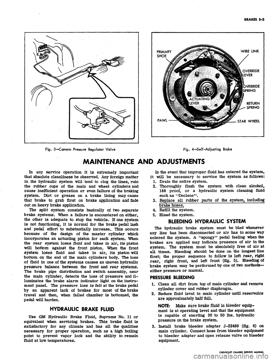
On Camaro models equipped with air conditioning, the
rear brake hydraulic line is routed through a pressure
regulator valve mounted on the left frame side rail
(fig. 3). The valve controls the hydraulic pressure to
the rear brakes resulting in the correct pressure balance
between the front and rear hydraulic systems.
The self-adjusting brakes (fig. 4), used on both front
and rear of all models, are the Duo-Servo single anchor
type which utilize the momentum of the vehicle to assist
in the brake application. The self-energizing or
self-
actuating force is applied to both brake shoes at each
wheel in both forward and reverse motion. The brake
shoe linings are bonded to the shoes.
Wheel cylinders are the double piston type permitting
even distribution of pressure to each brake shoe. To
keep out dust and moisture, both ejads of each wheel
cylinder are sealed with a rubber booC The wheel
cylinders have no adjustments.
The Chevrolet, Chevelle, and Camaro parking brakes
have a foot operated ratchet type pedal mounted to the
left of the steering column. A cable assembly connects
the pedal to an intermediate cable by means of an equal-
izer, where the adjustment for the parking brake is
incorporated. The intermediate cable attaches to the
CHEVROLET CHASSIS SERVICE MANUAL
Page 236 of 659
BRAKES
5-3
PRIMARY
SHOE
PAWL
WIRE LINK
OVERRIDE
LEVER
VERRIDE
SPRING
RETURN
SPRING
STAR
WHEEL
Fig.
3—Camaro
Pressure
Regulator
Valve
Fig.
4-Self-Adjusting
Brake
MAINTENANCE AND ADJUSTMENTS
In any service operation it is extremely important
that absolute cleanliness be observed. Any foreign matter
in the hydraulic system will tend to clog the lines, ruin
the rubber cups of the main and wheel cylinders and
cause inefficient operation or even failure of the braking
system. Dirt or grease on a brake lining may cause
that brake to grab first on brake application and fade
out on heavy brake application.
The split system consists basically of two separate
brake systems. When a failure is encountered on either,
the other is adequate to stop the vehicle. If one system
is not functioning, it is normal for the brake pedal lash
and pedal effort to substantially increase. This occurs
because of the design of the master cylinder which
incorporates ah actuating piston for each system. When
the rear system loses fluid and takes in air, its piston
will bottom against the front piston. When the front
system loses fluid and takes in air, its piston will
bottom on the end of the main cylinders body. The loss
of fluid in one of the systems causes an uneven hydraulic
pressure balance between the front and rear systems.
The brake pipe distribution and switch assembly, near
the main cylinder, detects the loss of pressure and il-
luminates the brake alarm indicator light on the instru-
ment panel. The pressure loss is felt at the brake pedal
by an apparent lack of brakes for most of the brake
travel and then, when failed chamber is bottomed, the
pedal will harden.
HYDRAULIC BRAKE FLUID
Use GM Hydraulic Brake Fluid, Supreme No. 11 or
equivalent when servicing brakes. This brake fluid is
satisfactory for any climate and has all the qualities
necessary for proper operation, such as a high boiling
point to prevent vapor lock and the ability to remain
fluid at low temperatures.
In the event that improper fluid has entered the system,
it will be necessary to service the system as follows:
1.
Drain the entire system.
2.
Thoroughly flush the system with clean alcohol,
188
proof,
or a hydraulic system cleaning fluid
such as "Declene".
3.
Replace all rubber parts of the system, including
brake hoses.
4.
Refill the system.
5. Bleed the system.
BLEEDING HYDRAULIC SYSTEM
The hydraulic brake system must be bled whenever
any line has been disconnected or air has in some way
entered the system. A ''spongy" pedal feeling when the
brakes are applied may indicate presence of air in the
system. The system must be absolutely free of air at
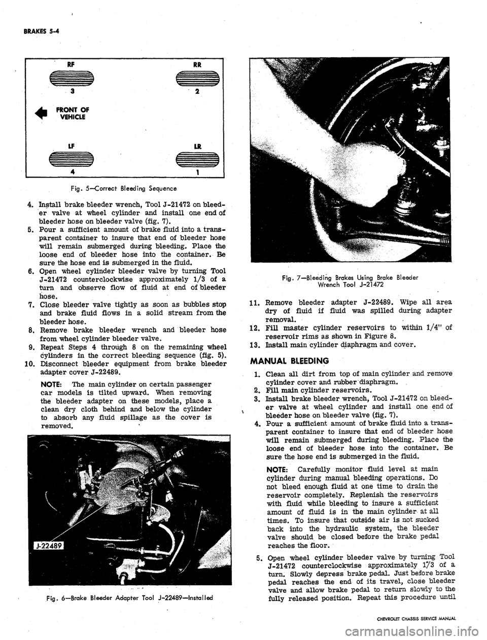
all times. Bleeding should be done on the longest line
first; the proper sequence to follow is left rear, right
rear, right front, and left front (fig. 5). Bleeding of
brake system may be performed by one of two methods—
either pressure or manual.
PRESSURE
BLEEDING
1.
Clean all dirt from top of main cylinder and remove
cylinder cover and rubber diaphragm.
2.
Reduce fluid level in main cylinder until reservoirs
are approximately half full.
NOTE:
Make sure brake fluid in bleeder equip-
ment is at operating level and that the. equipment
is capable of exerting 30 to 50 lbs. hydraulic
pressure on the brake system.
3.
Install brake bleeder adapter J-22489 (fig. 6) on
main cylinder. Connect hose from bleeder equipment
to bleeder adapter and open release valve on bleeder
equipment.
CHEVROLET CHASSIS SERVICE MANUAL
Page 237 of 659
BRAKES 5-4
RF
3
^ FRONT OF
~ VEHICLE
LF
4
RR
CZZZIZ3
2
LR
1
Fig.
5—Correct Bleeding Sequence
4.
Install brake bleeder wrench, Tool J-21472 on bleed-
er valve at wheel cylinder and install one end of
bleeder hose on bleeder valve (fig. 7).
5.
Pour a sufficient amount of brake fluid into a trans-
parent container to insure that end of bleeder hose
will remain submerged during bleeding. Place the
loose end of bleeder hose into the container. Be
sure the hose end is submerged in the fluid.
6. Open wheel cylinder bleeder valve by turning Tool
J-21472 counterclockwise approximately 1/3 of a
turn and observe flow of fluid at end of bleeder
hose.
7.
Close bleeder valve tightly as soon as bubbles stop
and brake fluid flows in a solid stream from the
bleeder hose.
8. Remove brake bleeder wrench and bleeder hose
from wheel cylinder bleeder valve.
9. Repeat Steps 4 through 8 on the remaining wheel
Cylinders in the correct bleeding sequence (fig. 5).
10.
Disconnect bleeder equipment from brake bleeder
adapter cover J-22489.
NOJE: The main cylinder on certain passenger
car models is tilted upward. When removing
the bleeder adapter on these models, place a
clean dry cloth behind and below the cylinder
to absorb any fluid spillage as the cover is
removed. v
Fig.
7—Bleeding Brakes Using Brake Bleeder
Wrench Tool J-21472
11.
adapter J-22489. Wipe all area
fluid was spilled during adapter
Fig.
6—Brake Bleeder Adapter Tool J-22489—Installed
Remove bleeder
dry of fluid if
removal.
12.
Fill master cylinder reservoirs to within 1/4" of
reservoir rims as shown in Figure 8.
13.
Install main cylinder diaphragm and cover.
MANUAL BLEEDING
1.
Clean all dirt from top of main cylinder and remove
cylinder cover and rubber diaphragm.
2.
Fill main cylinder reservoirs.
3.
Install brake bleeder wrench, Tool J-21472 on bleed-
er valve at wheel cylinder and install one end of
bleeder hose on bleeder valve (fig. 7).
4.
Pour a sufficient amount of brake fluid into a trans-
parent container to insure that end of bleeder hose
will remain submerged during bleeding. Place the
loose end of bleeder hose into the container. Be
sure the hose end is submerged in the fluid.
NOTE: Carefully monitor fluid level at main
cylinder during manual bleeding operations. Do
not bleed enough fluid at one time to drain the
reservoir completely. Replenish the reservoirs
with fluid while bleeding to insure a sufficient
amount of fluid is in the main cylinder at all
times.
To insure that outside air is not sucked
back into the hydraulic system, the bleeder
valve should be closed before the brake pedal
reaches the floor.
5.
Open wheel cylinder bleeder valve by turning Tool
J-21472 counterclockwise approximately 1/3 of a
turn. Slowly depress brake pedal. Just before brake
pedal reaches the end of its travel, close bleeder
valve and allow brake pedal to return slowly to the
fully released position. Repeat this procedure until
CHEVROLET CHASSIS SERVICE MANUAL
Page 257 of 659
BRAKES
5-24
DISC BRAKES
INDEX
Page
General Description
. 5-24
Maintenance
and
Adjustments
5-24
Bleeding Hydraulic System
5-24
Parking Brake Adjustment
-
Corvette
5-24
Component Replacement
and
Repairs
5-25
Page
Brake Shoes
. . . . . 5-25
Brake Caliper
5-26
Brake Disc
5-29
Main Cylinder.
5-30
Parking Brake Shoes
-
Corvette
5-30
GENERAL DESCRIPTION
Four wheel disc brakes
are
standard equipment
on
the
1967
Corvette,
as in 1966. The
Corvette
may
also
be equipped with heavy duty disc brakes which include
new front calipers, shoes, linings,
and
rear pressure
regulator valve. This heavy duty option
is
used
in
conjunction with
a
vacuum power unit. Front wheel disc
brakes
are
installed
as
optional equipment
on
Chevrolet,
Chevelle, Camaro,
and
Chevy
II
models.
The disc brake,
(fig. 35),
consists
of a
fixed caliper,
rotating disc, splash shield,
and
mounting bracket.
The
caliper assembly contains four pistons and two shoe
and
lining assemblies with
the
lining riveted
to the
steel
shoes.
A
seal
and
dust boot
are
installed
on
each piston,
with
a
piston spring
in the
caliper cylinder bore beneath
each piston.
A
retaining pin extends through each caliper
half
and
both shoes
to
hold
the
shoes and linings
in
posi-
tion
in the
caliper.
On
Corvette heavy duty disc brakes,
two retaining cotter pins
are
used
at
each end
of the
caliper
to
secure
the
shoes
and
linings. Machined
sur-
faces within
the
caliper prevent
the
shoe
and
lining
assembly from rotating with
the
brake disc when pres-
sure
is
applied.
The disc, which
has a
series
of air
vent louvers
to
provide cooling,
is
mounted
on the
front wheel-hub.
The caliper straddles
the
disc and mounts
on a
mounting
bracket attached
to the
steering knuckle with
two
bolts.
The Corvette heavy duty option includes
a
pressure
regulator valve mounted
in the
rear brake line just
below
the
main cylinder. Chevrolet, Chevelle, Camaro,
and Chevy
n
models with disc brakes have
a
pressure
regulator valve mounted
in the
front brake line just
below
the
main cylinder. The valve controls
the
hydraulic
pressure
to the
front
or
rear brakes,
as
applicable,
resulting,
in the
correct pressure balance between
the
front
and
rear hydraulic systems. This valve guards
against premature .lock-up
of
front
or
rear wheels when
brakes
are
applied.
Maintenance, adjustment,
and
service operations which
are
not
included
in
this section
are the
same
as for
the Duo-Servo type brakes.
MAINTENANCE
AND
ADJUSTMENTS
BLEEDING HYDRAULIC SYSTEM
The operation
of
bleeding
the
disc brake hydraulic
system
is the
same
as for
Duo-Servo system outlined
in
the
front
of
this section. Note
the
exceptions below
and refer
to
bleeding procedures under Duo-Servo
brakes.
1.
When pressure bleeding equipment
is
used,
the
correct pressure setting
for
bleeding disc brakes
is 10-2.0
lbs. on
Corvette,
and 40 lbs. on all
other
models.
2.
The
front calipers contain
one
bleeder valve.
The
rear calipers
on
Corvette contain two bleeder valves
(one inboard
and one
outboard) which necessitates
the removal
of the
rear wheels
for
bleeding.
3.
Tapping
the
caliper with
a
rawhide mallet
as the
fluid
is
flowing
out may
assist
in
obtaining
a
good
bleeding
job.
4.
On
Chevrolet, Chevelle, Camaro
and
Chevy
II, the
spring loaded
end of the
pressure regulator valve
(fig.
36)
must
be
held (valve
in
open position) while
bleeding. This
is
done
by
depressing
and
holding
in
the
plunger
in the
end
of
the valve either
by
hand,
by taping,
or by
clamping.
PARKING BRAKE-CORVETTE
Adjustment
1.
Raise rear
end of
vehicle
and
place
on
jack stands.
2.
Remove rear wheels.
3/
Loosen brake cables
at the
equalizer until
the
park-
ing brake levers move freely
to the "off"
position
with slack
in the
cables.
4.
Turn
the
disc until
the
adjusting screw can
be
seen
through
the
hole
in the
disc.
5. Insert
an
adjusting tool
or
screw driver through
the
hole
in the
disc
and
tighten
the
adjusting screw
by
moving your hand away from
the
floor
on
both
the
left and right sides
(fig. 37).
6. Tighten until
the
disc will
not
move, then back
off
ten
(10)
notches.
7. Apply
the
parking brake four
(4)
notches from inside
the
car.
8. Tighten
the
brake cables
at the
equalizer
to
produce
a light drag with
the
wheels mounted.
9. Fully release
the
parking brake handle
and
rotate
the rear wheels.
No
drag should be evident with
the
handle released.
CHEVROLET CHASSIS SERVICE MANUAL
Page 264 of 659
BRAKES
5-31
POWER BRAKES
INDEX
General Description 5-31
Maintenance
and"
Adjustments 5-31
Inspection . ... 5_31
Lubrication 5-31
Bleeding Instructions . . . 5.31
Air Cleaner Service . . . , 5.31
Page
Component Replacement 5-31
Power Brake Cylinder ......* 5-31
Removal . . 5-31
Disassembly and Assembly See Overhaul Manual
Installation . . . . 5-31
GENERAL DESCRIPTION
The Power Brake Unit is a self-contained hydraulic
and vacuum unit, utilizing manifold vacuum and atmos-
phere pressure for its power.
This unit permits the use of a low brake pedal as well
as less pedal effort than is required with the conventional
(nonpower) hydraulic brake system. Only two external
line connections are necessary -
one
a vacuum connection
from manifold to check valve located on front shell; the
other, a hydraulic connection from the main cylinder
outlet directly into the hydraulic system. The unit is
mounted on the engine side of the fire wall and directly
connected to the brake pedal.
MAINTENANCE AND ADJUSTMENTS
INSPECTIONS
1.
Check vacuum line and vacuum line connections as
well as vacuum check valve in front shell of power
unit for possible vacuum loss.
2.
Inspect all hydraulic lines and connections at the
wheel cylinders and main cylinder for possible
hydraulic leaks.
3.
Check brake assemblies for scored drums, grease
or brake fluid on linings, worn or glazed linings,
and make necessary adjustments.
4.
Check brake fluid level in the hydraulic reser-
voirs.
The reservoirs should be filled to the levels
shown in Figure 8.
5. Check for loose mounting bolts at main cylinder and
at power section.
6. Check air cleaner filter in power piston extension
and replace filter if necessary.
7. Check brake pedal for binding and misalignment
between pedal
-and
push rod.
LUBRICATION
The power brake unit is lubricated at assembly and
needs no further lubrication other than maintaining
normal reservoir fluid level. The reservoir should be
filled as described in this section.
BLEEDING INSTRUCTIONS
The power system may be bled manually or with a
pressure bleeder as outlined in this section. Use only
GM
Supreme 11 Brake Fluid or equivalent. Do not use the
power assist while bleeding. The engine should not be
running and the vacuum reserve should be reduced to
zero by applying the brake several times before starting
the bleeding procedure.
AIR CLEANER SERVICE
Servicing of the air cleaner is recommended and the
element replaced when restriction becomes severe
enough to affect power brake response. At any other
time, if cleaning of the filter is felt necessary, it should
be shaken free of dirt or washed in soap and water and
thoroughly dried.
COMPONENT REPLACEMENT
POWER BRAKE CYLINDER
Removal
1.
Remove vacuum hose from vacuum check valve.
2.
Disconnect hydraulic lines at main cylinder.
Disconnect push rod at brake pedal assembly.
Remove nuts and lock washers securing power unit
to fire wall, and remove power unit from engine
compartment.
3.
4.
NOTE:
Chevy
to fire wall.
has a three stud attachment
Repair procedures for the power cylinder are outlined
in the Brake Section of the Overhaul Manual-for service
of the main cylinder refer to applicable portion of
"Standard Brakes" in this manual.
Installation
1.
Mount the power brake assembly in place and install
the attaching nuts and lock washers.
2.
Attach vacuum line to check valve.
3.
Secure hydraulic lines to main cylinder.
4.
Attach push rod to brake pedal assembly, and check
operation of stop light.
5. Bleed brakes as outlined in this section.
CAUTION: After replacing the unit on the vehi-
cle,
start the engine and allow vacuum to build
up before applying the brake.
CHEVROLET CHASSIS SERVICE
Page 473 of 659
STEERING
9-33
POWER STEERING
INDEX
Page
General Description
. 9-33
Maintenance
and
Adjustments
9-33
Bleeding Hydraulic System
9-33
Fluid Level
. 9-33
Adjustments
. 9-34
Power Steering Gear
. . 9-34
Pump Belt Tension
9-34
Hydraulic System Checks
9-34
Component Replacement
and
Repairs
. 9-35
Power Steering Pump.
. 9-35
Power Steering Gear
9-36
Control Valve
and
Adapter Assembly
9.35
Power Cylinder
9.37
Power Steering Hoses
9.39
GENERAL DESCRIPTION
Two types
of
power steering
are
used
for 1967.
One
is
the conventional linkage type
for
Chevy
n and
Corvette
vehicles
and the
other
is the
integral gear type
for
Chevrolet, Chevelle,
and
Camaro.
For
both types
the
hydraulic pressure
is
provided
by an
engine-driven vane-
type pump.
On
the
Chevy
n and
Corvette linkage type power steer-
ing, hydraulic pressure
is
delivered through
a
hose from
the pump
to a
valve which senses
the
requirement
for
power assistance
and
supplies
the
power cylinder
ac-
cordingly.
The
steering gear used with this power steer-
ing
is the
same basic unit used
on
manually steered
vehicles;
it is
serviced
as
outlined
in the
manual steering
part
of
this section except
for
adjustment, which
is
covered
in the
following pages.
The
steering linkage also
is serviced the same
as
manual counterparts.
The Chevrolet, Chevelle
and
Camaro integral gear type
power steering
has the
hydraulic pressure delivered
from
the
pump through two hoses
to the
steering gear.
In
the power steering gear
the
steering shaft, hydraulic
valve, worm, and rack-piston
nut are all in
line making
a
compact
and
space saving assembly.
All oil
passages
are
internal within
the
gear except
the
pressure
and
return
hoses.
The steering gear
is a
recirculating ball system
in
which steel balls
act as a
rolling thread between
the
steering worm
and
rack-piston
nut. The
rack-piston
nut
is
all one
piece
and is
geared
to the
sector
of
the piston
shaft.
The
valve
is
contained
in the
gear housing elimi-
nating
the
need
of
bolts
or
seals
to
attach
a
separate
valve housing.
The valve
is an
open-center, rotary-type three
way
valve.
The
spool
is
held
in
neutral position by means
of a
torsion
bar. The
spool
is
attached
by
means
of
the stub
shaft
to one end of the
torsion
bar
and
to the
valve body
on
the
other
end.
Twisting
of the
torsion bar allows
the
spool
to
move
in
relation
to the
valve body thereby oper-
ating
the
valve.
MAINTENANCE
AND
ADJUSTMENTS
BLEEDING HYDRAULIC SYSTEM
1.
Fill
oil
reservoir
to
proper level and
let oil
remain
undistrubed
for at
least two minutes.
2.
Start engine
and run
only
for
about
two
seconds.
3.
Add
oil if
necessary.
4.
Repeat above procedure until
oil
level remains
con-
stant after running engine.
5. Raise front
end of
vehicle
so
that wheels
are off
the
ground.
6. Increase engine speed
to
approximately
1500 rpm.
7. Turn
the
wheels
(off
ground) right
and
left, lightly
contacting
the
wheel stops.
8. Add
oil if
necessary.
9. Lower
the car and
turn wheels right and left
on the
ground.
10.
Check
oil
level and refill
as
required.
11.
If oil is
extremely foamy, allow vehicle
to
stand
a
few minutes with engine
off and
repeat above
procedure.
,
a.
Check belt tightness
and
check
for a
bent
or
loose
pulley. (Pulley should
not
wobble with engine
running.)
b.
Check
to
make sure hoses
are not
touching
any
other parts
of the car,
particularly sheet metal.
c. Check
oil
level, filling
to
proper level
if
neces-
sary, following operations
1
through
10.
This
step
and
Step
"D" are
extremely important
as
low
oil
level and/or
air in the oil are the
most
frequent causes
of
objectionable pump noise.
d. Check
the
presence
of air in the oil. If air is
present, attempt
to
bleed system
as
described
in
operations
1
through
10. If it
becomes obvious
that
the
pump will
not
bleed after
a few
trials,
proceed
as
outlined under Hydraulic System
Checks.
FLUID
LEVEL
1.
Check
oil
level
in the
reservoir
by
checking
the dip
stick when
oil is at
operating temperature.
On
Chevelle models equipped with remote reservoir,
the reservoir should
be
maintained approximately
3/4 full when
oil is at
operating temperature.
2.
Fill,
if
necessary,
to
proper level with
GM
Power
Steering Fluid
or, if
this
is not
available, automatic
CHEVROLET CHASSIS SERVICE MANUAL
Page 615 of 659
ACCESSORIES
15-6
port thereby supplying vacuum to the Servo unit.
During system operation
the
following events occur:
1.
Car
speed below
20
mph—no function
of the
unit
because
the
rubber drum
has
not rotated
far
enough
to close
the
solenoid points.
No
energizing current
can flow through the solenoid coil.
2.
Car
speed above
20
mph—The tang
on the
rubber
drum
has
closed
the
solenoid points
and
current
is
flowing through
the 40 ohm
resistance wire
to the
solenoid coil. This current
is
not sufficient to "pull
in", the solenoid.
3.
Driver partially presses Engagement Switch—full
voltage flows through
the
solenoid
to
pull
it
into
operation. Solenoid
cam
tension
on the "U"
clip
is
released and the clip grips the rubber drum. Simul-
taneously the vacuum switch operates; applying man-
ifold vacuum
to the
Servo unit which tightens
the
throttle chain. When
the
driver releases pressure
from
the
accelerator pedal
the
unit will position the
throttle
to
maintain the speed
at
the time
of
solenoid
operation.
Driver releases
the
Engagement Switch—current
flows
to the
solenoid through
the 40
ohm wire and
since the solenoid is "pulled in", the reduced current
flow
is
sufficient to hold
it
in position.
The
car
begins
to
ascend
a
hill—car speed drops
slightly (very slightly) and the magnetic force on the
driven disk
of the
speed sensor
is
decreased.
The
disk rotates slightly
(as
would
a
speedometer shaft
because
of
hairspring tension) turning
the
rubber
drum. Since
the "U"
clip
is
gripping
the
drum,
it
moves
the
slide which COVERS
the air
bleed ports
more. With less air bleeding into the Servo, greater
vacuum exists
in it
and the diaphragm moves toward
the vacuum port opening
the
throttle wider.
The
tapered needle moves into the orifice further and the
diaphragm balances
in a
new position with the wider
throttle opening.
Car
speed
has
been maintained
automatically.
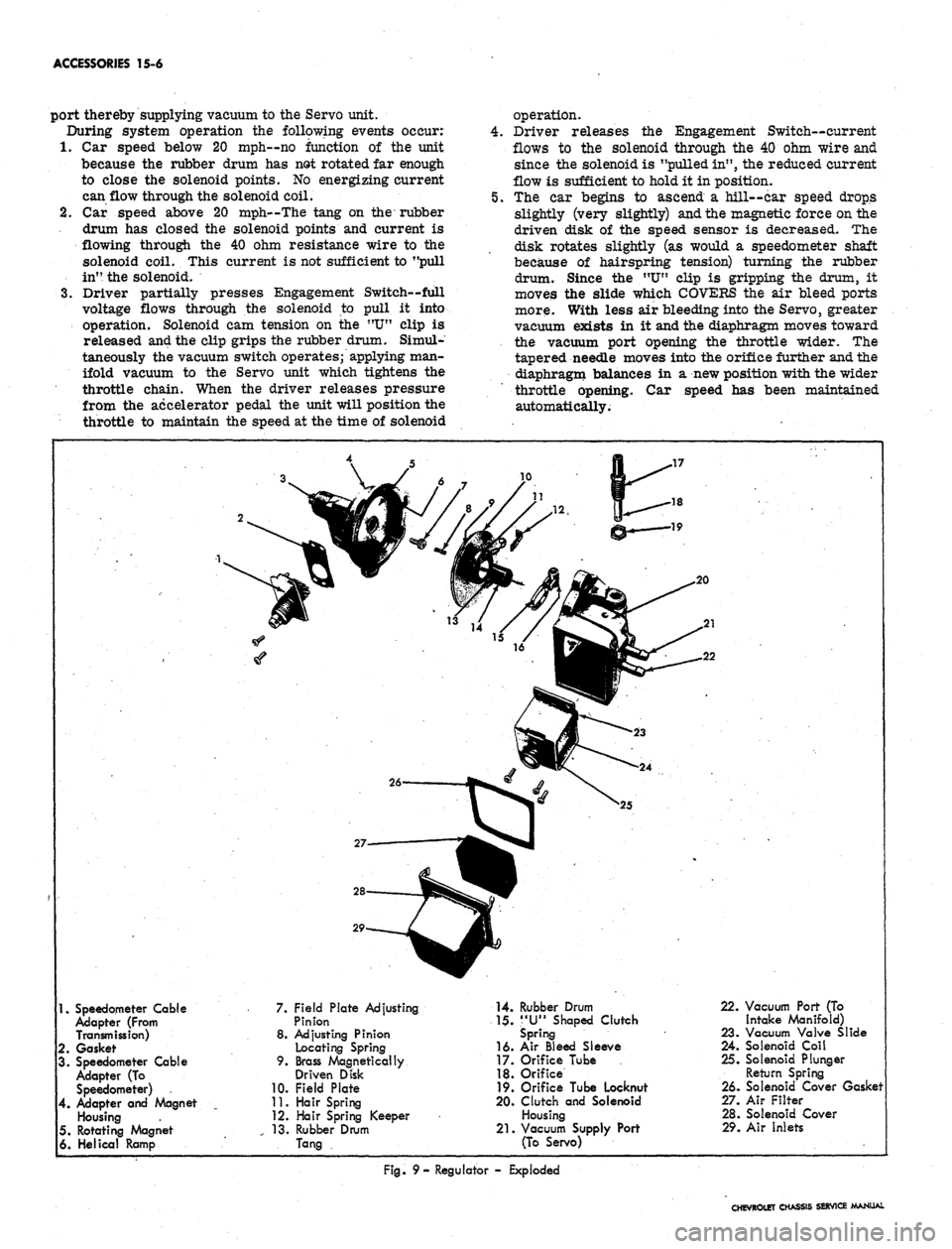
1.
Speedometer Cable
Adapter (From
Transmission)
2.
Gasket
3. Speedometer Cable
Adapter
(To
Speedometer)
4.
Adapter
and
Magnet
Housing
5. Rotating Magnet
6. Helical Ramp
7. Field Plate Adjusting
Pinion
8. Adjusting Pinion
Locating Spring
9. Brass Magnetically
Driven Disk
10.
Field Plate
11.
Hair Spring
12.
Hair Spring Keeper
13.
Rubber Drum
Tang
14.
Rubber Drum
1$.
"U"
Shaped Clutch
Spring
16.
Air
Bleed Sleeve
17.
Orifice Tube
18.
Orifice
19.
Orifice Tube Locknut
20.
Clutch
and
Solenoid
Housing
21.
Vacuum Supply Port
(To Servo)
22.
Vacuum Port (To
Intake Manifold)
23.
Vacuum Valve Slide
24.
Solenoid Coil
25.
Solenoid Plunger
Return Spring
26.
Solenoid Cover Gasket
27.
Air Filter
28.
Solenoid Cover
29.
Air Inlets
Fig.
9-
Regulator
-
Exploded
CHEVROLET CHASSIS SERVICE MANUAL
Page 616 of 659
ACCESSORIES 15-7
6. The car begins to descend a hill--car speed in-
creases slightly and the regulator movements oc-
curing above occur again except in reverse. The
rubber drum is turned further against spring tension
and the air bleed orifices are uncovered more. This
bleeds more air to the Servo reducing the vacuum in
the unit. The diaphragm moves away from the
vacuum port, closes the throttle slightly, and with-
draws the tapered needle from the vacuum orifice.
With the orifice enlarged, the increased vacuum
counteracts the increased air bleed and the dia-
phragm finds a balance again at a reduced throttle
opening.
7.
Driver accelerates by pressing accelerator pedal-
car speed increases and the system responds by
moving the diaphragm to decrease throttle opening.
Since a bead chain is used, the chain merely relaxes
and has no effect on throttle operation. After the
driver releases pressure from the pedal, the throttle
will close until car speed decreases to the pre-set
speed. At that point the Regulator bleeds less air
to the Servo which opens the throttle enough to
maintain the pre-set speed. The system returns to a
stable condition.
8. Driver desires higher controlled speed, presses ac-
celerator until new speed is reached, and depresses
Engagement Switch fully and releases button--speed
sensing assembly tries to turn in a direction that
would decrease the throttle opening until the driver
fully depresses the Engagement Switch. Then the
current is cut off to the solenoid which retracts; the
solenoid nose expands the "U" clip releasing its
grip on the rubber drum. The drum and disk as-
sembly then rotates to a new position because of the
higher car speed. When the solenoid retracts, it also
shuts off vacuum to the Servo and opens the vacuum
port to atmospheric pressure within the Regulator
thereby bleeding down the Servo toward idle throttle
position. As the driver releases the Engagement
Switch, the contacts cause "pull in" and "hold in" of
the solenoid respectively. The system is engaged to
maintain the car speed at the time of Engagement
Switch release.
9. Driver desires lower cruising speed, presses En-
gagement Switch fully, waits until car speed de-
creases to desired speed then releases Switch--when
the Engagement switch is fully depressed the sole-
noid is de-energized causing the vacuum switch to
bleed down the Servo to idle throttle position and the
"U"
clip of the idle bleed valve is released from the
rubber drum. The drum and disk assembly is free
to rotate to a position which corresponds to vehicle
speed as the car slows. When the driver releases
the Engagement Switch, the unit "pulls in" and "holds
in" in the normal manner. The air bleed valve is
clutched to, the rubber drum at the car speed during
switch release. Vacuum is again applied to the
Servo and throttle control is assumed by the Regu-
lator to maintain the car speed at the time of switch
release.
10.
With system in operation, driver applies brakes--
simultaneously the Vacuum Release and Electric
Release Switches operate. The Vacuum Switch
bleeds air into the Servo through the air bleed line
coming from the Regulator. The vacuum is reduced
in the Servo and the throttle returns to idle position.
The Electric Release Switch cuts off power to the
entire system and the solenoid is de-energized. If
the driver removes his foot from the brake pedal the
Electric Switch again feeds voltage to the Engage-
ment Switch and the Vacuum Switch seals the air
bleed line. If the vehicle speed is above 20 mph
when this occurs, reduced voltage will flow to the
solenoid through the 40 ohm wire which will not be
sufficient to "pull in" the unit. If vehicle speed is
below 20 mph no current will flow since the tang
on the rubber drum has opened the low limit switch
points in the Regulator. In either case, after de-
pressing the brake pedal, the system will not con-
trol car speed until the driver operates the engage-
ment switch above 20 mph.
SERVICE OPERATIONS
The components of the Cruise Master system are de-
signed to be replaced should they become inoperative.
The Regulator is calibrated in such a manner during
manufacturing that overhaul operations are impractical.
However, one adjustment may be made to the Regulator to
correct speed drop or increase at the time of
engagement.
BRAKE RELEASE SWITCHES
ELECTRIC
Service — An inoperative switch must be replaced.
Switch replacement is identical to standard brake lamp
switch replacement.
Adjustment- The brake switch plunger must clear the
pedal arm when the arm is moved 1/4 inch measured at
the switch (Figure 7).
VACUUM
Service
—
An inoperative (sticking, plugged, or leaking)
switch must be replaced. Switch replacement is similar
to brake switch replacement. Be certain that the hose to
the switch is connected firmly and is not cracked or
deteriorated.
Adjustment- The brake switch plunger must clear the
pedal arm when the arm is moved 5/16 inch measured at
the switch (Figure 7).
ENGAGEMENT SWITCH
Service
replacement.
The engagement is serviced only by
Removal
1.
Pry the engagement button out of the turn signal knob
with a small thin bladed screwdriver (Figure 2).
2.
With a small hook or long nosed pliers, remove the
switch retaining ring.
3.
.Pull switch outward utilizing the slack in the wiring
harness.
4.
With a small soldering iron, unsolder the wires and
resolder them to the correct terminals of the re-
placement switch.
CHEVROLET CHASSIS SERVICE MANUAL