electrical CHEVROLET CAMARO 1967 1.G Chassis User Guide
[x] Cancel search | Manufacturer: CHEVROLET, Model Year: 1967, Model line: CAMARO, Model: CHEVROLET CAMARO 1967 1.GPages: 659, PDF Size: 114.24 MB
Page 80 of 659
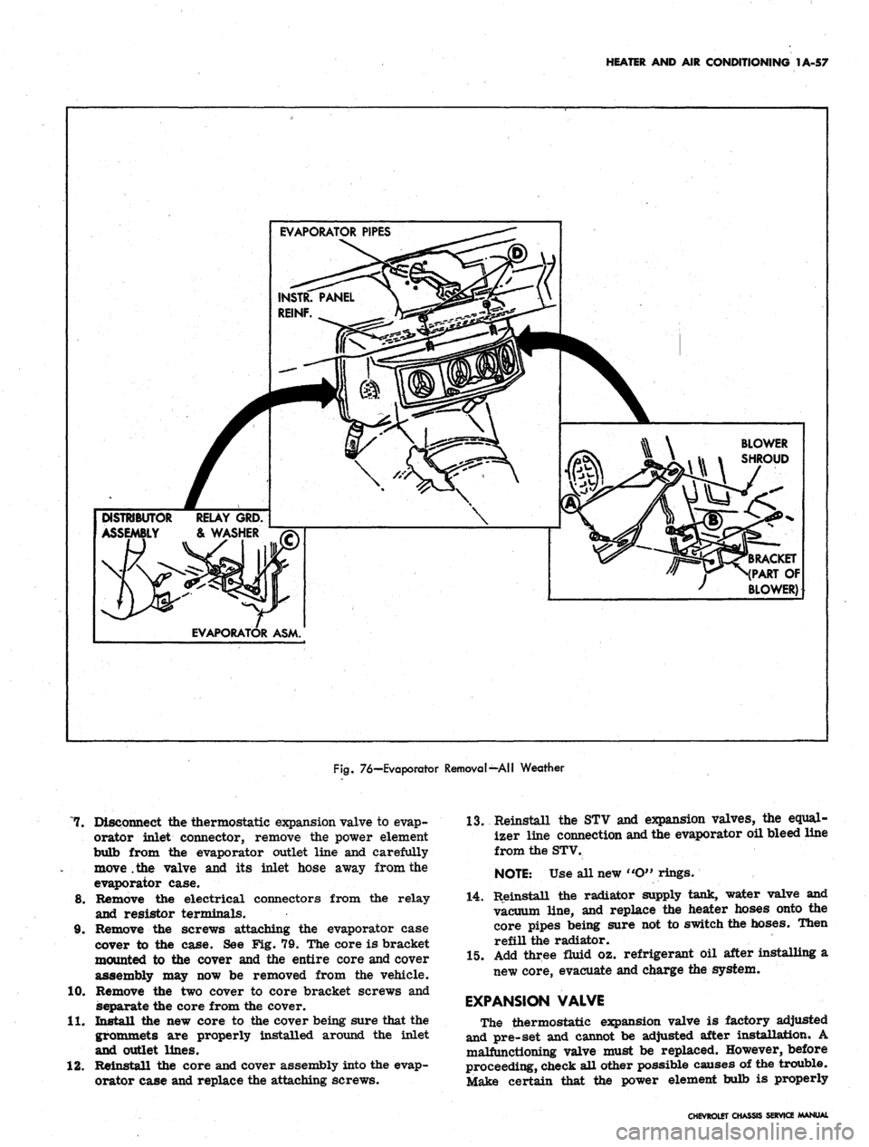
HEATER AND AIR CONDITIONING 1A-57
EVAPORATOR PIPES
DISTRIBUTOR RELAY GRD.
ASSEMBLY & WASHER
EVAPORATOR ASM.
BLOWER
SHROUD
(RACKET
(PART OF
BLOWER)
Fig.
76—Evaporator Removal—All Weather
7. Disconnect the thermostatic expansion valve to evap-
orator inlet connector, remove the power element
bulb from the evaporator outlet line and carefully
move .the valve and its inlet hose away from the
evaporator case.
8. Remove the electrical connectors from the relay
and resistor terminals.
9. Remove the screws attaching the evaporator case
cover to the case. See Fig. 79. The core is bracket
mounted to the cover and the entire core and cover
assembly may now be removed from the vehicle.
10.
Remove the two cover to core bracket screws and
separate the core from the cover.
11.
Install the new core to the cover being sure that the
grommets are properly installed around the inlet
and outlet lines.
12.
Reinstall the core and cover assembly into the evap-
orator case and replace the attaching screws.
13.
Reinstall the STV and expansion valves, the equal-
izer line connection and the evaporator oil bleed line
from the STV.
NOTE:
Use all new «O" rings.
14.
Reinstall the radiator supply tank, water valve and
vacuum line, and replace the heater hoses onto the
core pipes being sure not to switch the hoses. Then
refill the radiator.
15.
Add three fluid oz. refrigerant oil after installing a
new core, evacuate and charge the system.
EXPANSION VALVE
The thermostatic expansion valve is factory adjusted
and pre-set and cannot be adjusted after installation. A
malfunctioning valve must be replaced. However, before
proceeding, check all other possible causes of the trouble.
Make certain that the power element bulb is properly
CHEVROLET CHASSIS SERVICE MANUAL
Page 83 of 659
HEATER AND AIR CONDITIONING 1A-60
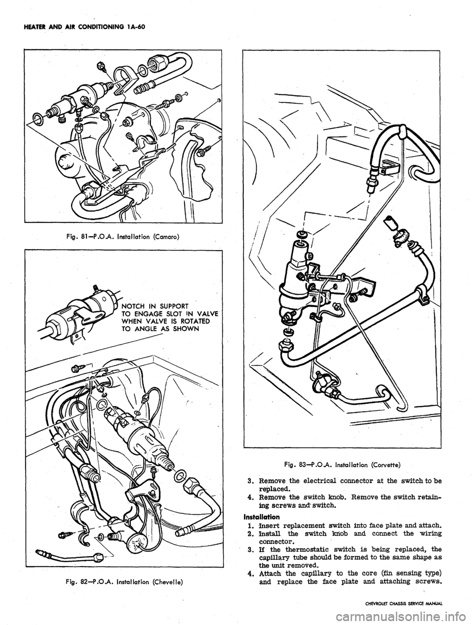
Fig.
81-P.O.A. Installation (Camaro)
NOTCH IN SUPPORT
TO ENGAGE SLOT !N VALVE
WHEN VALVE IS ROTATED
TO ANGLE AS SHOWN
Fig.
82-P.O.A. Installation (Chevelle)
Fig.
83—P.O.A. Installation (Corvette)
3.
Remove the electrical connector at the switch to be
replaced.
4.
Remove the switch knob. Remove the switch retain-
ing screws
and:
switch.
Installation
1.
Insert replacement switch into face plate and attach.
2.
Install the switch knob and connect the wiring
connector.
3.
If the thermostatic switch is being replaced, the
capillary tube should be formed to the same shape as
the unit removed.
4.
Attach the capillary to the core (fin sensing type)
and replace the face plate and attaching screws.
CHEVROLET CHASSIS SERVICE MANUAL
Page 84 of 659
HEATER AND AIR CONDITIONING 1A-61
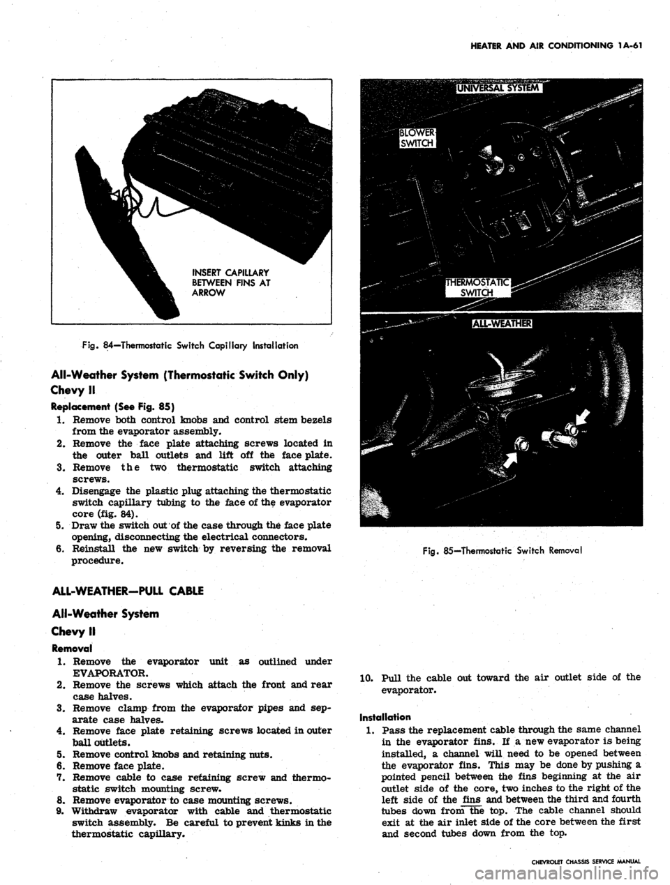
INSERT CAPILLARY
BETWEEN FINS AT
ARROW
Fig.
84—Thermostatic Switch Capillary Installation
All-Weather System (Thermostatic Switch Only)
Chevy II
Replacement (See Fig. 85)
1.
Remove both control knobs and control stem bezels
from the evaporator assembly.
2.
Remove the face plate attaching screws located in
the outer ball outlets and lift off the face plate.
3.
Remove the two thermostatic switch attaching
screws.
4.
Disengage the plastic plug attaching the thermostatic
switch capillary tubing to the face of the evaporator
core (fig. 84).
5. Draw the switch out of the case through the face plate
opening, disconnecting the electrical connectors.
6. Reinstall the new switch by reversing the removal
procedure.
Fig.
85—Thermostatic Switch Removal
unit as outlined under
ALL-WEATHER-PULL CABLE
All-Weather System
Chevy II
Removal
1.
Remove the evaporator
EVAPORATOR.
2.
Remove the screws which attach the front and rear
case halves.
3.
Remove clamp from the evaporator pipes and sep-
arate case halves.
4.
Remove face plate retaining screws located in outer
ball outlets.
5. Remove control knobs and retaining nuts.
6. Remove face plate.
7. Remove cable to case retaining screw and thermo-
static switch mounting screw.
8. Remove evaporator to case mounting screws.
9. Withdraw evaporator with cable and thermostatic
switch assembly. Be careful to prevent kinks in the
thermostatic capillary.
10.
Pull the cable out toward the air outlet side of the
evaporator.
Installation
1.
Pass the replacement cable through the same channel
in the evaporator fins. If a new evaporator is being
installed, a channel will need to be opened between
the evaporator fins. This may be done by pushing a
pointed pencil between the fins beginning at the air
outlet side of the core, two inches to the right of the
left side of the fins and between the third and fourth
tubes down from the top. The cable channel should
exit at the air inlet side of the core between the first
and second tubes down from the top.
CHEVROLET CHASSIS SERVICE MANUAL
Page 85 of 659
HEATER AND AIR CONDITIONING 1A-62
2.
Insert the evaporator assembly into the outlet case
half and mount the evaporator, thermostatic switch,
and cable to the case.
3.
Install the face plate to the case and install control
retaining nuts and knobs.
4.
Assemble the case halves and mount the evaporator
pipe clamp.
5. Install the evaporator assembly as previously
described under EVAPORATOR.
BLOWER ASSEMBLY
Four-Season System
Chevrolet and Camaro
Removal
1.
Disconnect battery ground cable.
2.
Remove the right front fender and skirt assembly.
3.
Disconnect the motor wire at the flange connector.
4.
Disconnect the rubber air cooling tube from the
motor.
5. Remove the motor to case attaching screws and re-
move the blower assembly. If the sealer acts as an
adhesive, pry the assembly carefully away from the
6. Remove the blower from the motor shaft.
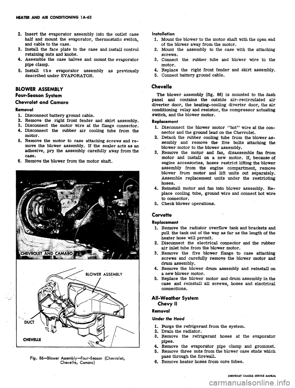
Fig.
86—Blower Assembly—Four-Season (Chevrolet,
Chevelle, Camaro)
Installation
1.
Mount the blower to the motor shaft with the open end
of the blower away from the motor.
2.
Mount the assembly to the case with the attaching
screws.
3.
Connect the rubber tube and blower wire to the
motor.
4.
Replace the right front fender and skirt assembly.
5. Connect battery ground cable.
Chevelle
The blower assembly (fig. 86) is mounted to the dash
panel and contains the outside air-recirculated air
diverter door, the heating-cooling diverter door, the air
conditioning relay and resistor, the compressor actuating
switch, and the blower motor.
Replacement
1.
Disconnect the blower motor "hot" wire at the con-
nector and the ground lead on the Chevrolet.
2.
Detach the rubber cooling tube from the blower as-
sembly and remove the five bolts attaching the
blower motor to the blower assembly.
3.
Remove the motor and fan, disassemble fan from
motor and install on a new motor. If, because of
engine accessories, hoses restrict lifting the blower
assembly from the engine compartment, remove
blower from motor and lift units out separately.
Assemble replacement units under the restricting
hoses.
4.
Reinstall motor and fan into blower assembly. Re-
place cooling tube, ground wire and connect hot wire
to connector.
5. Check blower operations.
Corvette
Replacement
1.
Remove the radiator overflow tank and brackets and
pull the tank out of the way as far as the length of the
heater hose will permit.
2.
Disconnect the electrical connector and the rubber
air inlet tube from the blower motor.
3.
Remove the five blower flange to case attaching
screws and carefully remove the blower motor and
drum assembly.
4.
Remove the blower drum assembly and reinstall on
a new blower motor.
5. Replace the blower motor and drum assembly in the
case and reinstall all screws, hoses and electrical
connections.
All-Weather System
Chevy II
Removal
Under the Hood
1.
Purge the refrigerant from the system.
2.
Drain the radiator.
3.
Remove the refrigerant hoses at the evaporator
pipes.
4.
Remove the evaporator pipe clamp and grommet.
5. Remove three nuts from the blower case studs which
pass through the firewall.
6. Remove heater hoses from core tubes.
CHEVROLET CHASSIS SERVICE MANUAL
Page 86 of 659
HEATER AND AIR CONDITIONING 1A-63
Under Dash
7. Remove ash tray and retainer, and glove box.
8. Remove blower case to air inlet adapter bracket
retaining screw.
9. Remove screw attaching air distributor to firewall.
10.
Remove nuts retaining evaporator case to lower lip
of dash. Withdraw evaporator drain tubes.
11.
Lower complete heater - air conditioning assembly.
12.
Remove screw retaining blower case to air distrib-
utor and separate them.
13.
Remove blower to case attaching screws. Disconnect
motor wire and remove blower assembly.
14.
Remove blower from motor shaft.
Installation
1.
Assemble blower to motor shaft.
2.
Mount motor in blower case and connect wire.
3.
Assemble blower case to air distributor and install
retaining screw.
4.
Lift the complete assembly into place and install
attaching screws and nuts.
5. Replace ash tray retainer and tray and glove box.
6. Replace nuts (engine side of dash) on heater case
studs and connect heater hoses.
7. Replace evaporator pipe clamp and grommet.
8. Replace the refrigerant hoses.
9. Evacuate and charge the refrigeration system and
refill the cooling system.
10.
Check system performance.
Universal Blower Assembly
Removal
1.
Remove the universal unit from its dash mounts.
2.
Remove the cover plate and separate the upper and
lower case halves. Remove blower motor mounting
strap screw and swing strap outward.
3.
Remove blower assembly. Loosen the blower wheel
setscrews and remove the wheels from the motor
shaft. . ' .
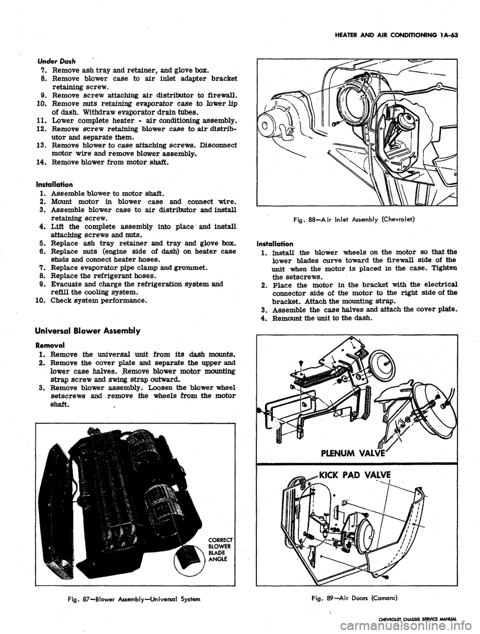
Fig.
88-Air Inlet Assembly (Chevrolet)
Installation
1.
Install the blower wheels on the motor so that the
lower blades curve toward the firewall side of the
unit when the motor is placed in the case. Tighten
the setscrews.
2.
Place the motor in the bracket with the electrical
connector side of the motor to the right side of the
bracket. Attach the mounting strap.
3.
Assemble the case halves and attach the cover plate.
4.
Remount the unit to the dash.
Fig.
87—Blower Assembly—Universal System
Fig.
89—Air Doors (Camaro)
CHEVROLET CHASSIS SERVICE
Page 96 of 659
HEATER AND AIR CONDITIONING 1A-73
Fig.
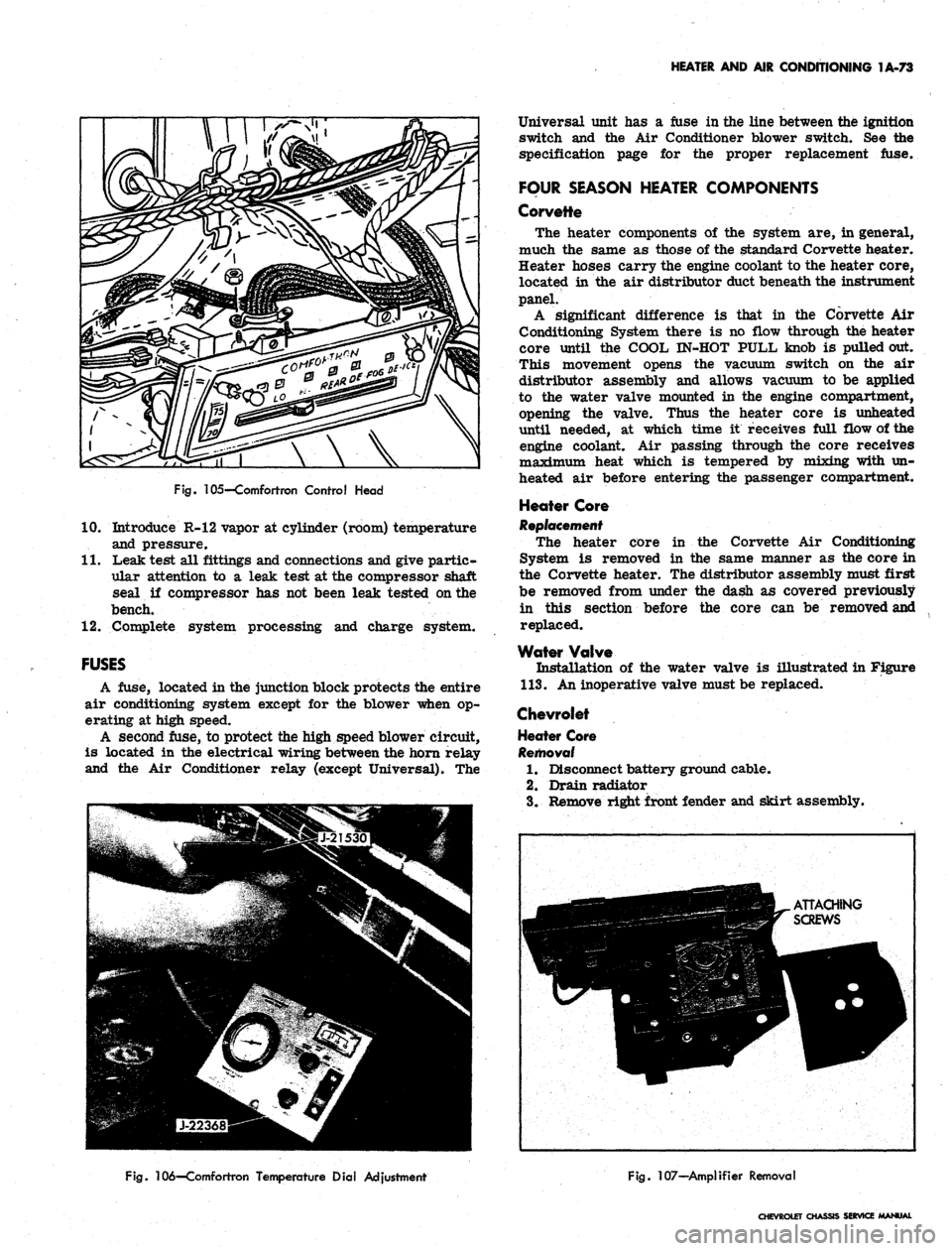
105—Comfortron Control Head
10.
Introduce R-12 vapor at cylinder (room) temperature
and pressure.
11.
Leak test all fittings and connections and give partic-
ular attention to a leak test at the compressor shaft
seal if compressor has not been leak tested on the
bench.
12.
Complete system processing and charge system.
FUSES
A fuse, located in the junction block protects the entire
air conditioning system except for the blower when op-
erating at high speed.
A second fuse, to protect the high speed blower circuit,
is located in the electrical wiring between the horn relay
and the Air Conditioner relay (except Universal). The
Universal unit has a fuse in the line between the ignition
switch and the Air Conditioner blower switch. See the
specification page for the proper replacement fuse.
FOUR SEASON HEATER COMPONENTS
Corvette
The heater components of the system are, in general,
much the same as those of the standard Corvette heater.
Heater hoses carry the engine coolant to the heater core,
located in the air distributor duct beneath the instrument
panel.
A significant difference is that in the Corvette Air
Conditioning System there is no flow through the heater
core until the COOL IN-HOT PULL knob is pulled out.
This movement opens the vacuum switch on the air
distributor assembly and allows vacuum to be applied
to the water valve mounted in the engine compartment,
opening the valve. Thus the heater core is unheated
until needed, at which time it receives full flow of the
engine coolant. Air passing through the core receives
maximum heat which is tempered by mixing with un-
heated air before entering the passenger compartment.
Heater Core
Replacement
The heater core in the Corvette Air Conditioning
System is removed in the same manner as the core in
the Corvette heater. The distributor assembly must first
be removed from under the dash as covered previously
in this section before the core can be removed and
replaced.
Water Valve
Installation of the water valve is illustrated in Figure
113.
An inoperative valve must be replaced.
Chevrolet
Heater Core
Removal
1.
Disconnect battery ground cable.
2.
Drain radiator
3.
Remove right front fender and skirt assembly.
Fig.
106—Comfortron Temperature Dial Adjustment
Fig.
107—Amplifier Removal
CHEVROLET CHASSIS SERVICE MANUAL
Page 99 of 659
HEATER AND AIR CONDITIONING 1A-76
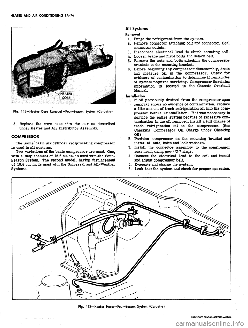
Fig.
112—-Heater Core Removal—Four-Season System (Corvette)
3.
Replace the core case into the car as described
under Heater and Air Distributor Assembly.
COMPRESSOR
The same basic six.cylinder reciprocating compressor
is used in all systems.
Two variations of the basic compressor are used. One,
with a displacement of 12.6 cu. in. is used with the Four-
Season System. The second model, having displacement
of 10.8 cu. in. is used with the Universal and All-Weather
Systems.
AH Systems
Removal
1.
Purge the refrigerant from the system.
2.
Remove connector attaching bolt and connector. Seal
connector outlets.
3.
Disconnect electrical lead to clutch actuating coil.
4.
Loosen brace and pivot bolts and detach belt.
5. Remove the nuts and bolts attaching the compressor
brackets to the mounting bracket.
6. Before beginning any compressor disassembly, drain
and measure oil in the compressor. Check for
evidence of contamination to ..determine if remainder
of system requires servicing. Compressor Servicing
information is located in the Chassis Overhaul
Manual.
Installation
1.
li oil previously drained from the compressor upon
removal shows no evidence of contamination, replace
a like amount of fresh refrigeration oil into the com-
pressor before reinstallatLon. If it was necessary to
service the entire system because of excessive con-
tamination in the oil removed, install a full charge of
"fresh refrigeration oil in the compressor. (See
Checking Compressor Oil Charge under Checking
Oil)
2.
Position compressor on the mounting bracket and
install all nuts, bolts and lock washers.
3.
Install the connector assembly to the compressor
rear head, using new "O" rings.
4.
Connect the electrical lead to the coil and install
and adjust compressor belt.
5. Evacuate and charge the system.
6. Leak test the system and check for proper operation.
Fig.
113—Heater Hoses^-Four-Season System (Corvette)
CHEVROLET CHASSIS SERVICE MANUAL
Page 112 of 659
CORVETTE BODY 1B-5
Fig.
4—Scribing
Line
Around
Hood
Hingje
2.
Remove cowl "kick" pad grille. |
3.
Disengage control cable fastened to cowl vent by nut
retainer. !
4.
Remove vent control knob retained by
|
set screw.
5. Remove center console trim and pass control cable
under instrument panel with care, avoiding damage
to electrical connections. j
Installation
Install vent assembly following removal procedure in
reverse order. Check operation of vent. Connect positive
battery cable.
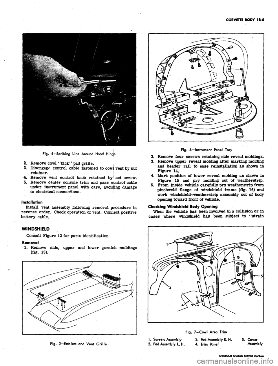
Fig.
6—Instrument
Panel Tray
2.
Remove four screws retaining side reveal moldings.
3.
Remove upper reveal molding after marking molding
and header rail to ease reinstallation as shown in
Figure 14.
4.
Mark position of lower reveal molding as shown in
Figure 15 and pry molding out of weatherstrip.
5. From inside vehicle carefully pry weatherstrip from
pinchweld flange of windshield frame (fig. 16) and
work windshield-weatherstrip assembly out of body
opening toward front of vehicle.
Checking Windshield Body Opening
When the vehicle has been involved in a collision or in
cases where windshield has been subject to "strain
WINDSHIELD
Consult Figure 12 for parts identification.
Removal
1.
Remove side, upper and lower garnish moldings
(fig. 13).
Fig.
5—Emblem dnd
Vent Grille
1.
Screen
Assembly
2.
Pad
Assembly
L H.
Fig.
7-Cowl
Area Trim
3.
Pad
Assembly
R. H. 5.
Cover
4.
Trim Panel
Assembly
CHEVROLET CHASSIS SERVICE MANUAL
Page 122 of 659
CORVETTE BODY 1B-15
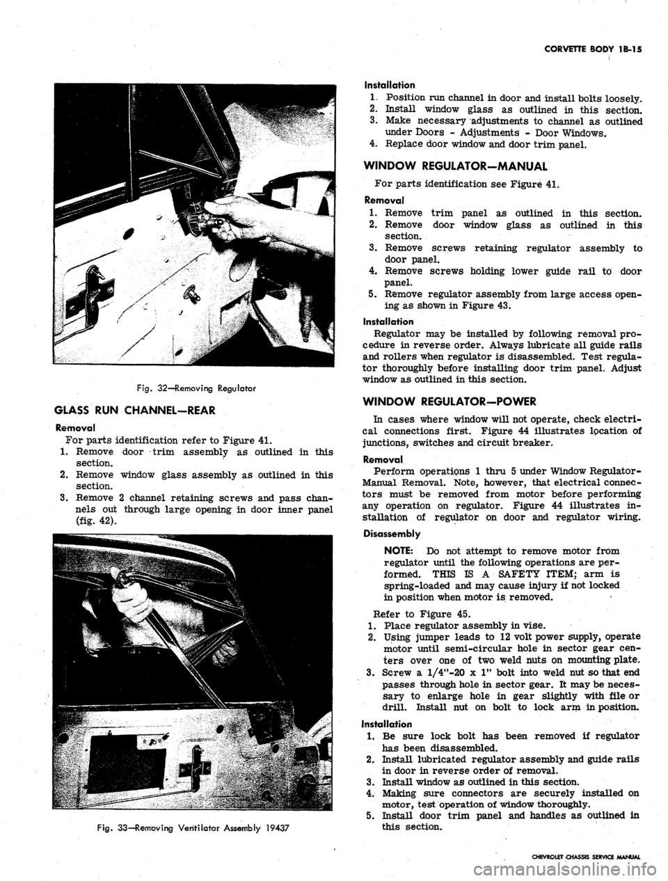
Fig.
32—Removing Regulator
GLASS RUN CHANNEL-REAR
Removal
For parts identification refer to Figure 41.
1.
Remove door trim assembly as outlined in this
section.
2.
Remove window glass assembly as outlined in this
section.
3.
Remove 2 channel retaining screws and pass chan-
nels out through large opening in door inner panel
(fig. 42).
Fig.
33—Removing Ventilator Assembly 19437
Installation
1.
Position run channel in door and install bolts loosely.
2.
Install window glass as outlined in this section.
3.
Make necessary adjustments to channel as outlined
under Doors - Adjustments - Door Windows.
4.
Replace door window and door trim panel.
WINDOW REGULATOR-MANUAL
For parts identification see Figure 41.
Removal
1.
Remove trim panel as outlined in this section.
2.
Remove door window glass as outlined in this
section.
3.
Remove screws retaining regulator assembly to
door panel.
4.
Remove screws holding lower guide rail to door
panel.
5. Remove regulator assembly from large access open-
ing as shown in Figure 43.
Installation
Regulator may be installed by following removal pro-
cedure in reverse order. Always lubricate all guide rails
and rollers when regulator is disassembled. Test regula-
tor thoroughly before installing door trim panel. Adjust
window as outlined in this section.
WINDOW REGULATOR-POWER
In cases where window will not operate, check electri-
cal connections first. Figure 44 illustrates lpcation of
junctions, switches and circuit breaker.
Removal
Perform operations 1 thru 5 under Window Regulator-
Manual Removal. Note, however, that electrical connec-
tors must be removed from motor before performing
any operation on regulator. Figure 44 illustrates in-
stallation of regulator on door and regulator wiring.
Disassembly
NOTE:
Do not attempt to remove motor from
regulator until the following operations are per-
formed. THIS IS A SAFETY ITEM; arm is
spring-loaded and may cause injury if not locked
in position when motor is removed.
Refer to Figure 45.
1.
Place regulator assembly in vise.
2.
Using jumper leads to 12 volt power supply, operate
motor until semi-circular hole in sector gear cen-
ters over one of two weld nuts on mounting plate.
3.
Screw a l/4"-20 x 1" bolt into weld nut so that end
passes through hole in sector gear. It may be neces-
sary to enlarge hole in gear slightly with file or
drill. Install nut on bolt to lock arm in position.
Installation
1.
Be sure lock bolt has been removed if regulator
has been disassembled.
2.
Install lubricated regulator assembly and guide rails
in door in reverse order of removal.
3.
Install window as outlined in this section.
4.
Making sure connectors are securely installed on
motor, test operation of window thoroughly.
5. Install door trim panel and handles as outlined in
this section.
CHEVROLET CHASSIS SERVICE MANUAL
Page 234 of 659
BRAKES
SECTION 5
CONTENTS OF THIS SECTION
Duo Servo Brakes
Disc Brakes
Page
5-1 Power Brakes
5-24 Special Tools
Page
5-31
5-32
DUO-SERVO BRAKES
INDEX
Page
General Description 5-1
Maintenance and Adjustments 5-3
Hydraulic Brake Fluid .. . 5-3
Bleeding Hydraulic System 5-3
Pressure Bleeding 5-3
Manual Bleeding 5_4
Push Rod to Main Cylinder Clearance 5-5
Hydraulic Brake Lines 5-5
Hydraulic Brake Hose 5-5
Hydraulic Brake Tubing 5-6
Brake Adjustment. .................... 5-7
Service Brake 5-7
Parking Brake 5-8
Component Replacement and Repairs 5-9
Parking Brake - Chevrolet, Chevelle and
Camaro 5^9
Pedal Assembly 5-9
Front Cable ,. . . 5-9
Center Cable 5-9
Rear Cables. . 5-9
Parking Brake - Chevy n 5-9
Lever Assembly 5-9
Idler Lever 5-11
Front Cable 5-11
Rear Cable . . ; 5-12
Parking Brake - Corvette 5-13
Lever Assembly . . . . 5-13
Front Cable 5-14
Rear Cable . . 5-14
Brake Pedal 5-15
Shoes and Linings 5-16
Organic 5-16
Metallic 5-17
Main Cylinder 5-18
Wheel Cylinders 5-21
Anchor Pin 5-22
Front Wheel 5-22
Rear Wheel 5-22
Brake Drums • 5-22
Brake Pipe Distribution and Switch Assembly . . . . . 5-23
Camaro Pressure Regulator Valve 5-23
GENERAL DESCRIPTION
All 1967 models are equipped with a new split brake
system as a safety feature. If a wheel cylinder or brake
line should fail at either the front end or rear end of
the vehicle, the operator can still bring the vehicle to
a controlled stop. The system is designed with separate
hydraulic systems for the front and rear brake using
a dual master cylinder (fig. 1). The design of the master
cylinder is similar to that used on the 1966 Corvette
in that it has two entirely separate reservoirs and outlets
in a common body casting. The front reservoir and outlet
is connected to the front wheel brakes, and the rear
reservoir and outlet is connected to the rear wheel
brakes. Two pistons within the master cylinder receive
mechanical pressure from the brake pedal push rod and
transmit it through the brake lines as hydraulic pressure
to the wheel cylinders. The filler cap is accessible from
inside the engine compartment.
A new brake pipe distribution and switch assembly
is mounted below the main cylinder. The front and rear
hydraulic brake lines are routed from the main cylinder,
through the brake pipe distribution and switch assembly,
to the front and rear brakes as shown in Figure 2. The
switch is wired electrically to the brake alarm indicator
light on the instrument panel. In the event of fluid loss
in either the front or rear brake system the indicator
on the instrument panel will illuminate red. (The indi-
cator will also' be illuminated when the parking brake is
applied.)
On Camaro models equipped with air conditioning, the
rear brake hydraulic line is routed through a pressure
regulator valve mounted on the left frame side rail
(fig. 3). The valve controls the hydraulic pressure to
the rear brakes resulting in the correct pressure balance
between the front and rear hydraulic systems.
The self-adjusting brakes (fig. 4), used on both front
and rear of all models, are the Duo-Servo single anchor
type which utilize the momentum of the vehicle to assist
in the brake application. The self-energizing or
self-
actuating force is applied to both brake shoes at each
wheel in both forward and reverse motion. The brake
shoe linings are bonded to the shoes.
Wheel cylinders are the double piston type permitting
even distribution of pressure to each brake shoe. To
keep out dust and moisture, both ejads of each wheel
cylinder are sealed with a rubber booC The wheel
cylinders have no adjustments.
The Chevrolet, Chevelle, and Camaro parking brakes
have a foot operated ratchet type pedal mounted to the
left of the steering column. A cable assembly connects
the pedal to an intermediate cable by means of an equal-
izer, where the adjustment for the parking brake is
incorporated. The intermediate cable attaches to the
CHEVROLET CHASSIS SERVICE MANUAL