seat adjustment CHEVROLET CAMARO 1967 1.G Chassis User Guide
[x] Cancel search | Manufacturer: CHEVROLET, Model Year: 1967, Model line: CAMARO, Model: CHEVROLET CAMARO 1967 1.GPages: 659, PDF Size: 114.24 MB
Page 240 of 659
BRAKES 5-7
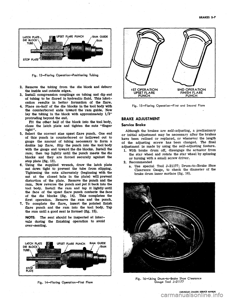
LATCH PLATE
DIE BLOCK
TUBE
UPSET FLARE PUNCH
RAM GUIDE
STOP PLATE
Fig.
13—Flaring Operation--Position ing Tubing
2.
Remove the tubing from the die block and deburr
the inside and outside edges.
3.
Install compression couplings on tubing and dip end
of tubing to be flared in hydraulic fluid. This lubri-
cation results in better formation of the flare.
4.
Place on-half of the die blocks in the tool body with
the counterbored ends toward the ram guide. Now
lay the tubing in the block with approximately 1/2"
protruding beyond the end.
Fit the other half of the block into the tool body,
close the latch plate and tighten the nuts "finger
tight".
5. Select the correct size upset flare punch. One end
of this punch is counterbored or hollowed out to
gauge the amount of tubing necessary to form a
double lap flare. Slip the punch into the tool body
with the gauge end toward the die blocks. Install the
ram; then tap lightly until the punch meets the die
, blocks and they are forced securely against the
stop plate (fig. 13).
6. Using the supplied wrench, draw the latch plate
nut down tight to prevent the tube from slipping.
Tightening the nuts alternately (beginning with the
nut at the closed hole in the plate) will prevent
distortion of the plate. Remove the punch and the
ram. Now reverse the punch and put it back into the
tool body. Install the ram and tap it lightly until
the face of the upset flare punch contacts the face
of the die blocks (fig. 14). This completes the
first operation. Remove the ram and the punch.
7. To complete the flare, insert the pointed finish
flare punch and the ram into the tool body. Tap
the ram until a good seat is formed (fig. 15).
NOTE:
The seat should be inspected at inter-
vals during the finishing operation to avoid
over-seating.
LATCH
DIE BLOCK
TUBE
UPSET FLARE PUNCH
RAM GUIDE
RAM
1ST OPERATION
UPSET FLARE
PUNCH
2ND OPERATION
FINISH FLARE
PUNCH
Fig.
15—Flaring Operation—First and Second Flare
BRAKE ADJUSTMENT
Service Brake
Although the brakes are self-adjusting, a preliminary
or initial adjustment may be necessary after the brakes
have been relined or replaced, or whenever the length
of the adjusting screw has been changed. The final
adjustment is made by using the self-adjusting feature.
1.
With brake drum off, disengage the actuator from
the star wheel and rotate the star wheel by spinning
or turning with a small screw driver.
2.
Recommended
a. Use special Tool J-21177; Drum-to-Brake Shoe
Clearance Gauge, to check the diameter of the
brake drum inner surface (fig. 16).
Fig.
14—Flaring Operation—First Flare
Fig.
16—Using Drum-to-Brake Shoe Clearance
Gauge Tool J-21177
CHEVROLET CHASSIS SERVICE MANUAL
Page 247 of 659
BRAKES 5-14
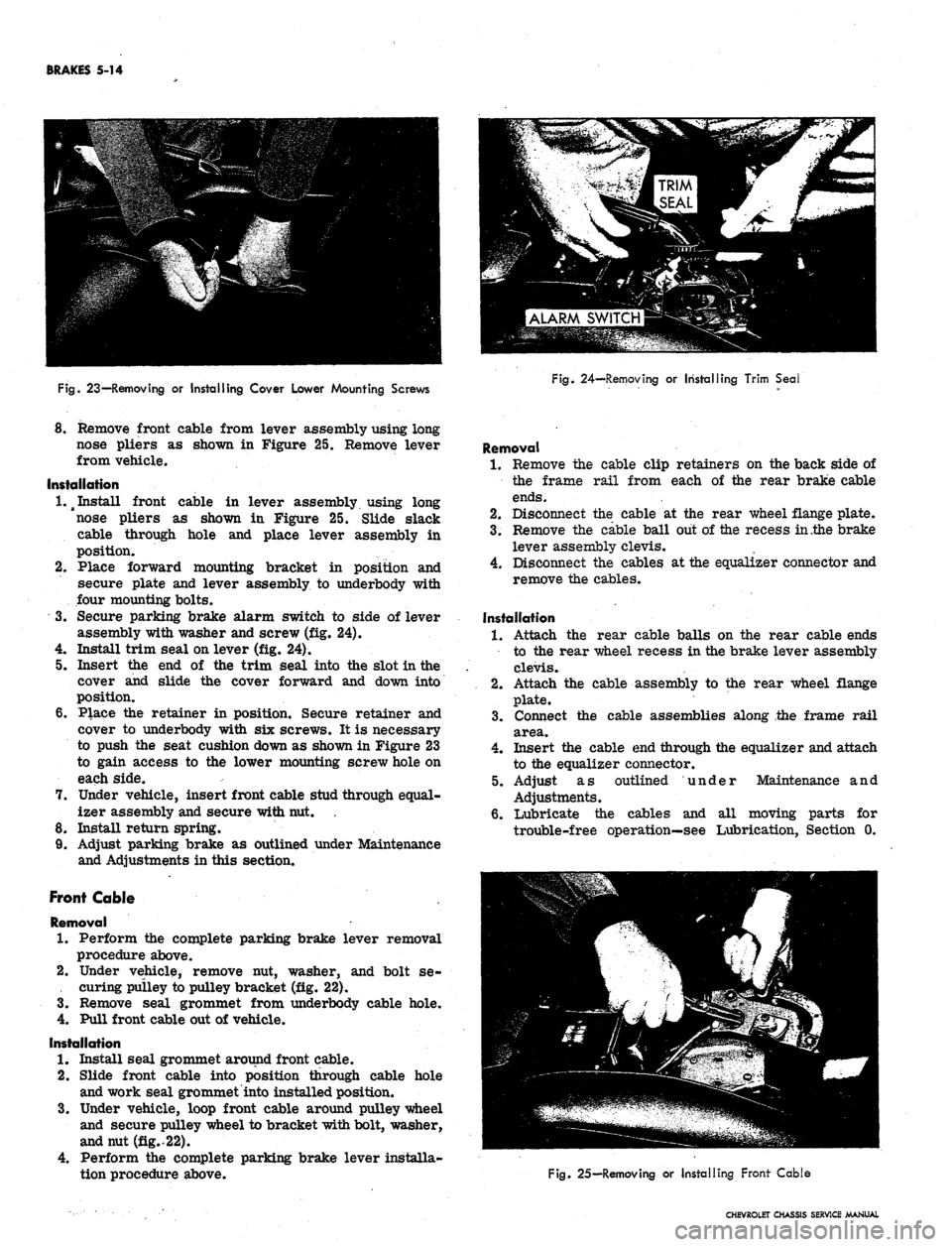
Fig.
23—Removing or Installing Cover Lower Mounting Screws
Fig.
24—Removing or Installing Trim Seal
8. Remove front cable from lever assembly using long
nose pliers as shown in Figure 25. Remove lever
from vehicle.
Installation
1.^
Install front cable in lever assembly using long
nose pliers as shown in Figure 25. Slide slack
cable through hole and place lever assembly in
position.
2.
Place forward mounting bracket in position and
secure plate and lever assembly to underbody with
four mounting bolts.
3.
Secure parking brake alarm switch to side of lever
assembly with washer and screw (fig. 24).
4.
Install trim seal on lever (fig. 24).
5. Insert the end of the trim seal into the slot in the
cover and slide the cover forward and down into
position.
6. Place the retainer in position. Secure retainer and
cover to underbody with six screws. It is necessary
to push the seat cushion down as shown in Figure 23
to gain access to the lower mounting screw hole on
each side.
7. Under vehicle, insert front cable stud through equal-
izer assembly and secure with nut.
8. Install return spring.
9. Adjust parking brake as outlined under Maintenance
and Adjustments in this section.
Front Cable
Removal
1.
Perform the complete parking brake lever removal
procedure above.
2.
Under vehicle, remove nut, washer, and bolt se-
. curing pulley to pulley bracket (fig. 22).
3.
Remove seal grommet from underbody cable hole.
4.
Pull front cable out of vehicle.
Installation
1.
Install seal grommet around front cable.
2.
Slide front cable into position through cable hole
and work seal grommet into installed position.
3.
Under vehicle, loop front cable around pulley wheel
and secure pulley wheel to bracket with bolt, washer,
and nut (fig..22).
4.
Perform the complete parking brake lever installa-
tion procedure above.
Removal
1.
Remove the cable clip retainers on the back side of
the frame rail from each of the rear brake cable
ends.
2.
Disconnect the cable at the rear wheel flange plate.
3.
Remove the cable ball out of the recess in .the brake
lever assembly clevis.
4.
Disconnect the cables at the equalizer connector and
remove the cables.
Installation
1.
Attach the rear cable balls on the rear cable ends
to the rear wheel recess in the brake lever assembly
clevis.
2.
Attach the cable assembly to the rear wheel flange
plate.
3.
Connect the cable assemblies along the frame rail
area.
4.
Insert the cable end through the equalizer and attach
to the equalizer connector.
5. Adjust as outlined under Maintenance and
Adjustments.
6. Lubricate the cables and all moving parts for
trouble-free operation—see Lubrication, Section 0.
Fig.
25—Removing or Installing Front Cable
CHEVROLET CHASSIS SERVICE MANUAL
Page 250 of 659
BRAKES 5-17
mended shoe and lining assemblies. Otherwise,
serious fade or failure may occur.
1.
Inspect new linings and make certain there are no
nicks or burrs on bonding material on shoe edge
where contact is made with brake flange plate or
on any of the contact surfaces.
NOTE: Keep hands clean while handling brake
shoes.
Do not permit oil or grease to come in
contact with linings.
2.
If working on rear brakes, lubricate parking brake
cable.
3.
On rear brakes only, lubricate fulcrum end of park-
ing brake lever and the bolt with brake lube, then
attach lever to secondary shoe with bolt, spring
washer, lock washer and nut. Make sure that lever
moves freely.
4.
Before installation make certain the adjusting screw
is clean and lubricated properly.
NOTE: Loose adjustment may occur from an
adjusting screw that is not properly operating.
If the lubrication in the adjusting screw as-
sembly is contaminated or destroyed, the ad-
justing screw should be thoroughly cleaned and
lubricated.
5.
Connect brake shoes together with adjusting screw
spring, then place adjusting screw, socket and nut
in position.
CAUTION: Make sure the proper adjusting
screw is used ("L" for left side of vehicle,
"R"
for right side of vehicle). The star wheel
should only be installed with the star wheel
nearest to the secondary shoe and the adjusting
screw spring inserted to prevent interference
with the star wheel.
6. On rear wheels connect parking brake cable to lever.
7.
Secure the primary brake shoe (short lining—faces
forward) first with the hold-down pin and spring
using a pair of pliers. Engages shoes with the wheel
cylinder connecting links.
8. Install and secure the actuator assembly and second-
ary brake shoe with the hold-down pin and spring
using a pair of needle nose pliers. On rear wheels
position parking brake strut and strut spring.
9. Install guide plate over anchor pin.
10.
Install the wire link.
NOTE: Do not hook the wire link over the
anchor pin stud with the regular spring hook
tool. This may damage the cylinder boot seals.
Fasten the wire link to the actuator assembly ;
first, then place over the anchor pin stud by
hand while holding the adjuster assembly in the
full down position.
11.
Install actuator return spring.
NOTE: Do not pry actuator lever to install re-
turn spring. Ease it in place using the end of a
screw driver or other suitable flat tool.
12.
If old brake pull back (return) springs are nicked,
distorted or if strength is doubtful, install new
springs.
13.
Hook springs in shoes using Tool J-8049 by in-
stalling the primary spring from the shoe over the
anchor pin and then spring from secondary shoe
over the wire link end.
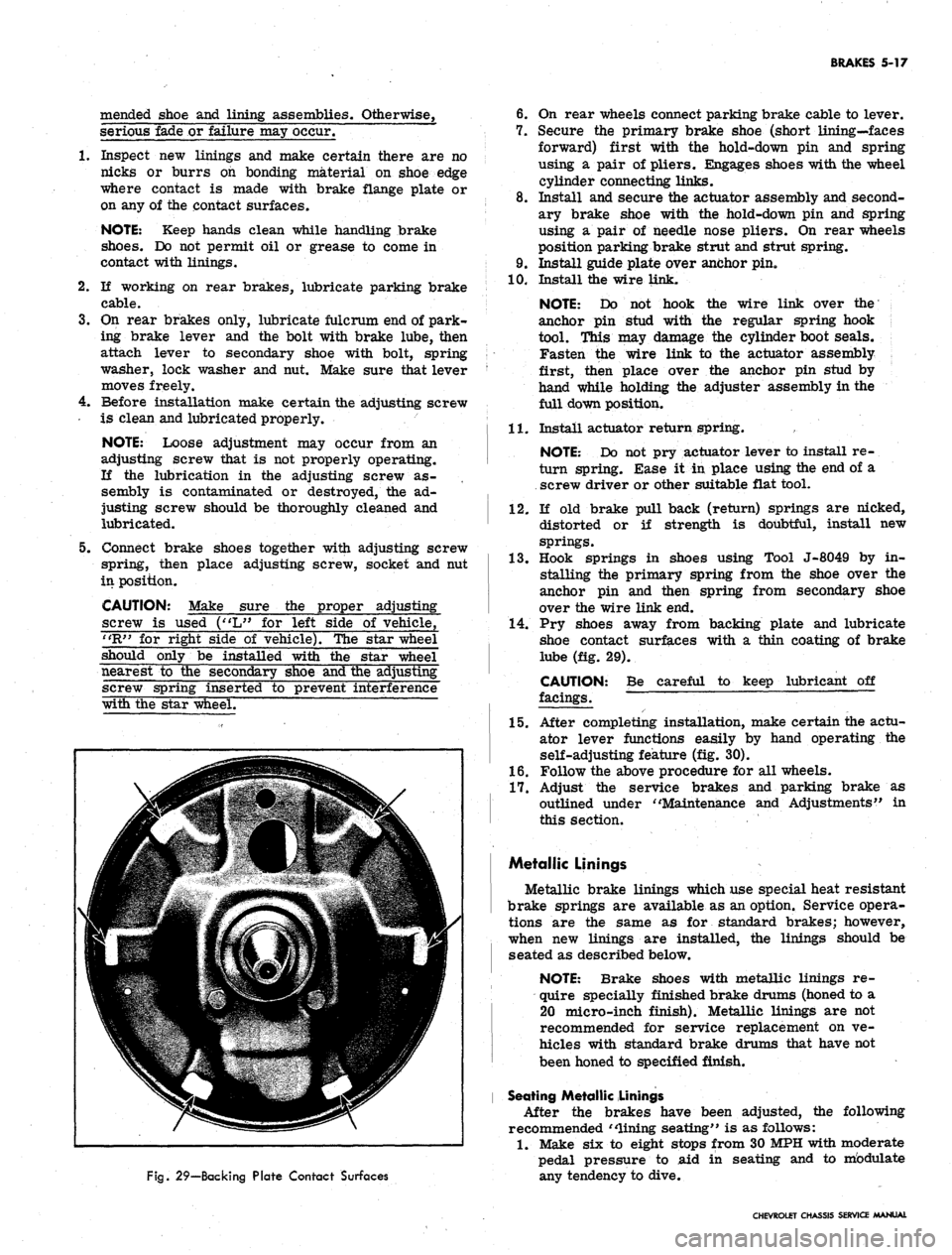
14.
Pry shoes away from backing plate and lubricate
shoe contact surfaces with a thin coating of brake
lube (fig. 29).
CAUTION:
facings.
Be careful to keep lubricant off
Fig.
29—Backing Plate Contact Surfaces
15.
After completing installation, make certain the actu-
ator lever functions easily by hand operating the
self-adjusting feature (fig. 30).
1.6. Follow the above procedure for all wheels.
17.
Adjust the service brakes and parking brake as
outlined under "Maintenance and Adjustments" in
this section.
Metallic Linings
Metallic brake linings which use special heat resistant
brake springs are available as an option. Service opera-
tions are the same as for standard brakes; however,
when new linings are installed, the linings should be
seated as described below.
NOTE: Brake shoes with metallic linings re-
quire specially finished brake drums (honed to a
20 micro-inch finish). Metallic linings are not
recommended for service replacement on ve-
hicles with standard brake drums that have not
been honed to specified finish.
Seating Metallic Linings
After the brakes have been adjusted, the following
recommended "lining seating" is as follows:
1.
Make six to eight stops from 30 MPH with moderate
pedal pressure to aid in seating and to mbdulate
any tendency to dive.
CHEVROLET CHASSIS SERVICE MANUAL
Page 254 of 659
BRAKES 5-21
brake fluid. Coat the primary and secondary seals
on the secondary piston with clean brake fluid. Insert
the secondary piston spring retainer into the sec-
ondary piston spring. Place the retainer and spring
down over the end of the secondary piston until the
retainer locates inside of the lips of the primary
cup.
10.
Hold the master cylinder with the open end of the
bore down. Push the secondary piston into the bore
until the spring seats against the closed end of the
bore.
11.
Position the master cylinder in a vise with the
open end of the bore up. Coat the primary and
secondary seal on the primary piston with clean
brake fluid. Push the primary piston assembly,
spring end first, into the bore of the master cylinder*
Hold the piston down and snap the lock ring into
position in the small groove in the I.D. of the bore.
12.
Push the primary piston down to move the secondary
piston forward far enough to clear the stop screw
hole in the bottom of the front fluid reservoir. Install
the stop screw.
13.
Install reservoir diaphragm in the reservoir cover
and install the cover on the main cylinder. Push
bail wire into position to secure the reservoir cover.
Installation
1.
Assemble the push rod through the push rod retainer,
if it has been disassembled.
2.
Push the retainer over the end of the main cylinder.
Assemble new boot over push rod and press it down
over the push rod retainer. Slide new mounting
gasket into position.
3.
Secure .the main cylinder to the firewall with mount-
ing bolts.
4.
Connect the push rod clevis to the brake pedal with
pin and retainer.
5. Connect the brake lines to the main cylinder.
6. Fill the main cylinder reservoirs to the levels
shown in Figure 8. Bleed the brake system as out-
lined in this section.
7. K necessary, adjust the brake pedal free play as
outlined in this section.
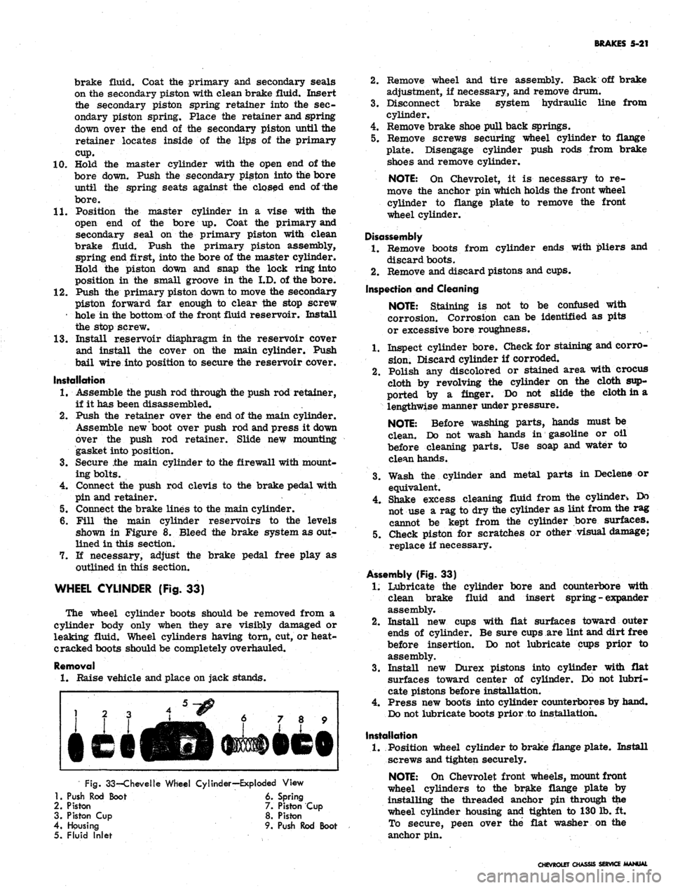
WHEEL CYLINDER (Fig. 33)
The wheel cylinder boots should be removed from a
cylinder body only when they are visibly damaged or
leaking fluid. Wheel cylinders having torn, cut, or heat-
cracked boots should be completely overhauled.
Removal
1.
Raise vehicle and place on jack stands.
Fig.
33-Chevelle Wheel Cylinder—Exploded View
1.
Push Rod Boot 6. Spring
2.
Piston 7. Piston Cup
3. Piston Cup 8. Piston
4.
Housing 9. Push Rod Boot
5. Fluid Inlet
2.
Remove wheel and tire assembly. Back off brake
adjustment, if necessary, and remove drum.
3.
Disconnect brake system hydraulic line from
cylinder.
4.
Remove brake shoe pull back springs.
5. Remove screws securing wheel cylinder to flange
plate. Disengage cylinder push rods from brake
shoes and remove cylinder.
NOTE:
On Chevrolet, it is necessary to re-
move the anchor pin which holds the front wheel
cylinder to flange plate to remove the front
wheel cylinder.
Disassembly
1.
Remove boots from cylinder ends with pliers and
discard boots.
2.
Remove and discard pistons and cups.
Inspection and Cleaning
NOTE:
Staining is not to be confused with
corrosion. Corrosion can be identified as pits
or excessive bore roughness.
1.
Inspect cylinder bore. Check for staining and corro-
sion.
Discard cylinder if corroded.
2.
Polish any discolored or stained area with crocus
cloth by revolving the cylinder on the cloth sup-
ported by a finger. Do not slide tfce cloth in a
lengthwise manner under pressure.
NOTE:
Before washing parts, hands must be
clean. Do not wash hands in gasoline or oil
before cleaning parts. Use soap and water to
clean hands.
3.
Wash the cylinder and metal parts in Declene or
equivalent.
4.
Shake excess cleaning fluid from the cylinder-. Do
not use a rag to dry the cylinder as lint from the rag
cannot be kept from the cylinder bore surfaces.
5. Check piston for scratches or other visual damage;
replace if necessary.
Assembly (Fig. 33)
1.
Lubricate the cylinder bore and counterbore with
clean brake fluid and insert spring - expander
assembly.
2.
Install new cups with flat surfaces toward outer
ends of cylinder. Be sure cups are lint and dirt free
before insertion. Do not lubricate cups prior to
assembly.
3.
Install new Durex pistons into cylinder with flat
surfaces toward center of cylinder. Do not lubri-
cate pistons before installation.
4.
Press new boots into cylinder counterbores by hand.
Do not lubricate boots prior to installation.
Installation
1.
Position wheel cylinder to brake flange plate. Install
screws and tighten securely.
NOTE:
On Chevrolet front wheels, mount front
wheel cylinders to the brake flange plate by
installing the threaded anchor pin through the
wheel cylinder housing and tighten to 130 lb. ft.
To secure, peen over the flat washer on the
anchor pin.
CHEVROLET CHASSIS SERVICE MANUAL
Page 273 of 659
ENGINE
6-8
Check
and
Adjust Ignition Timing
(Fig. 13)
1.
Disconnect
the
distributor spark advance hose
and
plug
the
vacuum source opening.
2.
Start engine
and run at
idle speed
(see
tune
up
chart).
3.
Aim
timing light
at
timing
tab.
NOTE:
- The
markings
on the
tabs
are in 2°
increments
(the
greatest number
of
markings
on
the
"A"
side
of the "O"). the "O"
markings
is
TDC
of
#1 cylinder
and all
BTDC settings fall
on
the
"A"
(advance) side
of "O".
4.
Adjust
the
timing
by
loosening
the
distributor clamp
and
,
rotating
the
distributor body
as
required, then
tighten
the
clamp.
5.
Stop engine
and
remove timing light
and
reconnect
the spark advance hose.
Adjust Idle Speed
and
Mixture
(Fig. 14)
(Except when
equipped with
Air
Injection Reactor System)
1.
As a
preliminary adjustment, turn idle mixture
screws lightly
to
seat
and
back
out 2
turns.
CAUTION:
Do not
turn idle mixture screw
tightly against seat
or
damage
may
result.
2.
With engine running
at
operating temperature (choke
wide open) adjust idle speed screw
to
bring idle
speed
to
specified
rpm
(automatic transmission
in
drive, manual transmission
in
neutral).
3.
Adjust idle mixture screw
to
obtain highest steady
idle speed
(1/4
turn
out
from lean roll).
4.
Repeat Steps
2 and 3 as
needed
for
final adjustment.
5.
Shut down
the
engine, remove gauges
and
install
air
cleaner.
Adjust Idle Speed
and
Mixture
(Fig. 14)
(With
Air
Injection Reactor System)
The recommended adjustment procedure
for Air
Injec-
tion Reactor System equipped engines
is as
follows:
1.
As a
preliminary adjustment, turn idle mixture
screws lightly
to
seat
and
than back
out 3
turns.
CAUTION:
Do not
turn idle mixture screw
tightly against seat
or
damage
may
result.
2.
With engine running
at
operating temperature, choke
wide open,
and
parking brake applied, adjust idle
specified idle speed (automatic
"drive"-manual transmission
in
to
in
screw
transmission
"neutral").
;3.
Adjust idle mixture screw (turn
in) to
"lean roll"
position; then turn screw
out 1/4
turn
(1/4
turn rich
from "lean roll").
The
definition
of
"lean roll" point
is
a 20 to 30 rpm
drop
in
engine speed, obtained
by
leaning
the
idle mixture.
4.
Repeat Steps
2 and 3 as
needed
for
final adjustments.
ADDITIONAL CHECKS
AND
ADJUSTMENTS
Testing Crankcase Ventilation Valve
(Fig. 15) 0
1.
Connect tachometer
and
vacuum gauge
as for
idle
speed
and
mixture adjustment.
2.
Set
parking brake, start engine
and
adjust idle speed
and mixture.
3.
Disconnect ventilation hose
at
valve, block opening
of
valve
and
read engine
rpm
change.
4.
A
change
of
less than
50 rpm
indicates
a
plugged
ventilation valve
-
replace
the
valve.
Cylinder Balance Test
(Fig. 16)
It
is
often difficult
to
locate
a
weak cylinder.
A com-
pression test,
for
example, will
not
locate
a
leaky intake
manifold,
a
valve
not
opening properly
due to a
worn
camshaft,
or a
defective spark plug.
With
the
cylinder balance test,
the
power output
of one
cylinder
may be
checked against another, using
a set of
grounding leads. When
the
power output
of
each cylinder
is
not
equal,
the
engine will lose power
and run
roughly.
Perform
a
cylinder balance test
as
follows:
1.
Connect
the
tachometer
and
vacuum gauge.
2.
Start engine
and run at 1500 rpm.
3.
Ground large clip
of
grounding leads
and
connect
in-
dividual leads
to all
spark plugs except
the
pair being
tested.
Divide
the
firing order
in
half
and
arrange
one
half
over
the
other.
The
cylinders
to be
tested together
ap-
pear
one
over
the
other.
L4 Firing Order
V8 Firing Order
1-8-4-3-6-5-7-2
1-6, 8-5, 4-7, 3-2
1-3-4-2
= 1-3
4-2
L6 Firing Order
1-5-3-6-2-4
=
=
1-4. 3-2
1-5-3
6-2-4
1-6, 5-2, 3-4
1-8-4-3
6-5-7-2
4.
Operate engine
on
each pair
of
cylinders
in
turn
and
note engine
rpm and
manifold vacuum
for
each pair.
A variation
of
more than
1
inch
of
vacuum
or 40 rpm
between pairs
of
cylinders being tested indicates that
the cylinders
are off
balance.
Battery
The battery should
be
checked with special testing
equipment
and to the
equipment manufacturers specifica-
tions.
See
Section 6Y
for
complete information
on
battery
tests.
Ignition
The following additional ignition checks
may be
made
with
any of
several pieces
of
equipment available
for un-
covering
the
source
of
engine difficulties.
The
specific
operating instructions
of the
equipment manufacturer
should
be
followed:
Cranking voltage
Ignition switch
Distributor resistance
Secondary resistance
Ignition output
and
secondary leakage
Cranking Voltage
(Fig. 17)
1.
Disconnect coil primary lead
at the
coil negative
terminal
to
prevent engine from firing during
cranking.
2.
Connect voltmeter between primary terminal
of coi|
(resistance wire side)
and
ground.
3.
Operate starting motor.
CHEVROLET CHASSIS SERVICE MANUAL
Page 279 of 659
ENGINE 6-14
b.
Bolt transmission to engine, then raise engine and
transmission assembly and install flywheel to
converter attaching bolts.
c. Install converter
housing*
underpan and starter.
3.
Tilt and lower engine and transmission assembly into
the chassis as a unit, guiding engine to align front
mounts with frame supports.
4.
Install front mount through bolts and torque to
specifications.
5.
Raise engine enough to install rear crossmember,
then install crossmember, install rear mount, lower
engine and torque bolts to specifications.
6. Remove lifting device and lifting adapter then install
rocker arm cover as outlined.
7.
On synchromesh equipped vehicles, install clutch
cross shaft engine bracket, then adjust and connect
clutch as outlined in Section 7.
8. Connect:
• Speedometer cable.
• Shift linkage at transmission.
9; Install propeller shaft.
10.
Remove jack stands and lower vehicle.
11.
Connect:
Power steering pump lines (if disconnected).
Vacuum line to power brake unit (if disconnected).
Fuel line at fuel pump.
Exhaust pipe at manifold flange.
Accelerator linkage at manifold bellcrank.
12.
Connect wires at:
Coil
Oil pressure switch
Temperature switch
Delcotron
Starter solenoid
13.
Install pulley, fan blade and fan belt as outlined in
Section 6K.
14.
Install radiator and shroud as outlined in Section 13.
15.
Install and adjust hood as outlined in Section 11.
16.
Connect battery cables.
17.
Fill with coolant, engine oil and transmission oil,
then start engine and check for leaks.
18.
Perform necessary adjustments and install air
cleaner.
MANIFOLD ASSEMBLY
Removal
1.
Remove air cleaner.
2.
Disconnect both throttle rods at bellcrank and re-
move throttle return spring.
3.
Disconnect fuel and vacuum lines at carburetor.
Disconnect choke cable on \A engines.
4.
Disconnect crankcase ventilation hose at rocker arm
cover.
5.
Disconnect exhaust pipe at manifold flange and dis-
card packing.
6. Remove manifold attaching bolts and clamps then
remove manifold assembly and discard gaskets.
7.
Check for cracks in manifold castings.
8. If necessary to replace either intake or exhaust
manifolds, separate them by removing one bolt and
two nuts at center of assembly. Reassemble mani-
folds using a new gasket. Tighten finger tight and
torque to specifications after assembly to cylinder
head. Transfer all necessary parts.
Installation
1.
Clean gasket surfaces on cylinder head and
manifolds*
2.
Position new gasket over manifold end studs on head
and carefully install the manifold in position making
sure the gaskets are in place.
3.
Install bolts and clamps while holding manifold in
place with hand.
4.
Torque bolts to specifications.
NOTE: On L6 engines center bolt and end bolt
torque differ.
5.
Connect exhaust pipe to manifold using a new
packing.
6. Connect crankcase ventilation hose at rocker arm
cover.
7.
Connect fuel and vacuum lines at carburetor.
8. On L4 engines connect choke cable and adjust as out-
lines in Section 6M.
9. Connect throttle rods at bellcrank and install throttle
return spring.
10.
Install air cleaner, start engine, check for leaks and
adjust carburetor idle speed and mixture.
ROCKER ARM COVER
Removal
1.
Disconnect crankcase ventilation hose(s) at rocker
arm cover.
2.
Remove air cleaner.
3.
Disconnect temperature wire from rocker arm cover
clips.
4.
Remove rocker arm cover. '
CAUTION: Do Not pry rocker arm cover loose
Gaskets adhering to cylinder head and rocker
arm cover may be sheared by bumping end of
rocker arm cover rearward with palm of hand or
a rubber mallet.
Installation
1.
Clean gasket surfaces on cylinder head and rocker
arm cover with degreaser then, using anew gasket,
install rocker arm cover and torque bolts to
specifications.
2.
Connect temperature wire at rocker arm cover clips.
3.
Install air cleaner.
4.
Connect crankcase ventilation hoses.
VALVE MECHANISM
Removal
1.
Remove rocker arm cover as outlined.
2.
Remove rocker arm nuts, rocker arm
balls,
rocker
arms and push rods.
NOTE:
Place rocker arms, rocker arm balls
and push rods in a rack so they may be rein-
stalled in the same location.
Installation and Adjustment
NOTE:
Whenever new rocker arms and/or
rocker arm balls are being installed, coat bear-
ing surfaces of rocker arms and rocker arm
balls with Molykote or its equivalent.
1.
Install push rods,
socket.
Be sure push rods seat in lifter
CHEVROLET CHASSIS SERVICE MANUAL
Page 280 of 659
ENGINE 6-15
2.
Install rocker arms, rocker arm balls and rocker
arm
nuts.
\
Tighten rocker arm nuts until all lash is
eliminated. .
3.
Adjust valves when lifter is on base circle of cam-
shaft lobe as follows:
a. Mark distributor housing, with chalk, at each cyl-
inder position (plug wire) then disconnect plug
wires at spark plugs and coil and remove distri-
butor cap and plug wire assembly (if not previ-
ously done).
b.
Crank engine until distributor rotor points to
number one cylinder position and breaker points
are open. Both valves on number one cylinder
may now be adjusted.
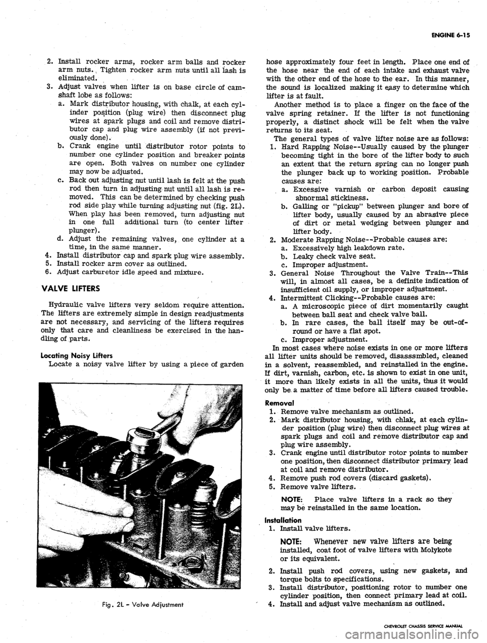
c. Back out adjusting nut until lash is felt at the push
rod then turn in adjusting nut until all lash is re-
moved. This can be determined by checking push
rod side play while turning adjusting nut (fig. 2L).
When play has been removed, turn adjusting nut
in one full additional turn (to center lifter
plunger).
d. Adjust the remaining valves, one cylinder at a
time,
in the same manner.
4.
Install distributor cap and spark plug wire assembly.
5.
Install rocker arm cover as outlined.
6. Adjust carburetor idle speed and mixture.
VALVE LIFTERS
Hydraulic valve lifters very seldom require attention.
The lifters are extremely simple in design readjustments
are not necessary, and servicing of the lifters requires
only that care and cleanliness be exercised in the han-
dling of parts.
Locating Noisy Lifters
Locate a noisy valve lifter by using a piece of garden
Fig.
2L - Valve Adjustment
hose approximately four feet in length. Place one end of
the hose near the end of each intake and exhaust valve
with the other end of the hose to the ear. In this manner,
the sound is localized making it easy to determine which
lifter is at fault.
Another method is to place a finger on the face of the
valve spring retainer. If the lifter is not functioning
properly, a distinct shock will be felt when the valve
returns to its seat.
The general types of valve lifter noise are as follows:
1.
Hard Rapping Noise--Usually caused by the plunger
becoming tight in the bore of the lifter body to such
an extent that the return spring can no longer push
the plunger back up to working position. Probable
causes are:
a. Excessive varnish or carbon deposit causing
abnormal stickiness.
b.
Galling or "pickup" between plunger and bore of
lifter body, usually caused by an abrasive piece
of dirt or metal wedging between plunger and
lifter body.
2.
Moderate Rapping Noise--Probable causes are:
a. Excessively high leakdown rate.
b.
Leaky check valve seat.
c. Improper adjustment.
3.
General Noise Throughout the Valve Train—This
will, in almost all cases, be a definite indication of
insufficient oil supply, or improper adjustment.
4.
Intermittent Clicking—Probable causes are:
a. A microscopic piece of dirt momentarily caught
between ball seat and check valve ball.
b.
In rare cases, the ball itself may be
out-of-
round or have a flat spot.
c. Improper adjustment.
In most cases where noise exists in one or more lifters
all lifter units should be removed, disasssmbled, cleaned
in a solvent, reassembled, and reinstalled in the engine.
If dirt, varnish, carbon, etc. is shown to exist in one unit,
it more than likely exists in all the units, thus it would
only be, a matter of time before all lifters caused trouble.
Removal
1.
Remove valve mechanism as outlined.
2.
Mark distributor housing, with chlak, at each cylin-
der position (plug wire) then disconnect plug wires at
spark plugs and coil and remove distributor cap and
plug wire assembly.
3.
Crank engine until distributor rotor points to number
one position, then disconnect distributor primary lead
at coil and remove distributor.
4.
Remove push rod covers (discard gaskets).
5.
Remove valve lifters.
NOTE: Place valve lifters in a rack so they
may be reinstalled in the same location.
Installation
1.
Install valve lifters.
NOTE:
Whenever new valve lifters are being
installed, coat foot of valve lifters with Molykote
or its equivalent.
2.
Install push rod covers, using new gaskets, and
torque bolts to specifications.
3.
Install distributor, positioning rotor to number one
cylinder position, then connect primary lead at coil.
4.
Install and adjust valve mechanism as outlined.
CHEVROLET CHASSIS SERVICE MANUAL
Page 292 of 659
ENGINE 6-27
and spark plug shields.
4.
Remove exhaust manifold flange nuts, then lower ex-
haust pipe assembly (hang exhaust pipe from frame
with wire).
5.
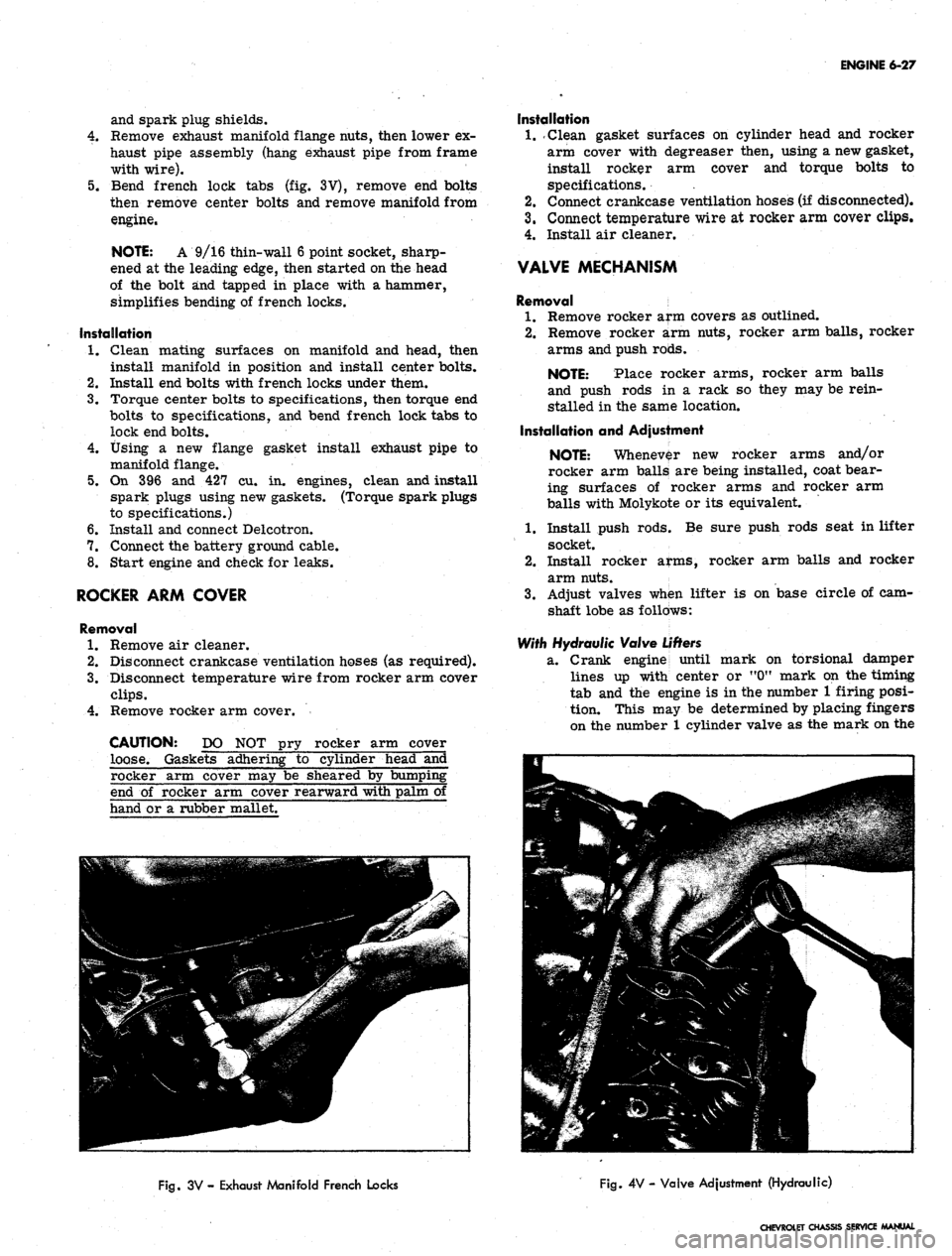
Bend french lock tabs (fig. 3V), remove end bolts
then remove center bolts and remove manifold from
engine.
NOTE: A 9/16 thin-wall 6 point socket, sharp-
ened at the leading edge, then started on the head
of the bolt and tapped in place with a hammer,
simplifies bending of french locks.
Installation
1.
Clean mating surfaces on manifold and head, then
install manifold in position and install center bolts.
2.
Install end bolts with french locks under them.
3.
Torque center bolts to specifications, then torque end
bolts to specifications, and bend french lock tabs to
lock end bolts.
4.
Using a new flange gasket install exhaust pipe to
manifold flange.
5.
On 396 and 427 cu. in. engines, clean and install
spark plugs using new gaskets. (Torque spark plugs
to specifications.)
6. Install and connect Delcotron.
7.
Connect the battery ground cable.
8. Start engine and check for leaks.
ROCKER ARM COVER
Removal
1.
Remove air cleaner.
2.
Disconnect crankcase ventilation hoses (as required).
3.
Disconnect temperature wire from rocker arm cover
clips.
4.
Remove rocker arm cover.
CAUTION: DO NOT pry rocker arm cover
loose. Gaskets adhering to cylinder head and
Installation
1.
.Clean gasket surfaces on cylinder head and rocker
arm cover with degreaser then, using a new gasket,
install rocker arm cover and torque bolts to
specifications. .
2.
Connect crankcase ventilation hoses (if disconnected).
3.
Connect temperature wire at rocker arm cover clips.
4.
Install air cleaner.
VALVE MECHANISM
Removal
1.
Remove rocker arm covers as outlined.
2.
Remove rocker arm nuts, rocker arm balls, rocker
arms and push rods.
NOTE: Place rocker arms, rocker arm balls
and push rods in a rack so they may be rein-
stalled in the same location.
Installation and Adjustment
NOTE: Whenever new rocker arms and/or
rocker arm balls are being installed, coat bear-
ing surfaces of rocker arms and rocker arm
balls with Molykote or its equivalent.
1.
Install push rods; Be sure push rods seat in lifter
socket.
2.
Install rocker arms, rocker arm balls and rocker
arm nuts.
3.
Adjust valves when lifter is on base circle of cam-
shaft lobe as follows:
With Hydraulic Valve
Lifters
2L.
Crank engine until
mark on torsional damper
lines up with center or "0M mark on the timing
tab and the engine is in the number 1 firing posi-
tion. This may be determined by placing fingers
on the number 1 cylinder valve as the mark on the
rocker arm cover may be sheared by bumpii
end of rocker arm cover rearward with palm
hand or a rubber mallet.
Fig.
3V - Exhaust Manifold French Locks
Fig.
4V - Valve Adjustment (Hydraulic)
CHEVROLET CHASSIS SERVICE MANUAL
Page 293 of 659
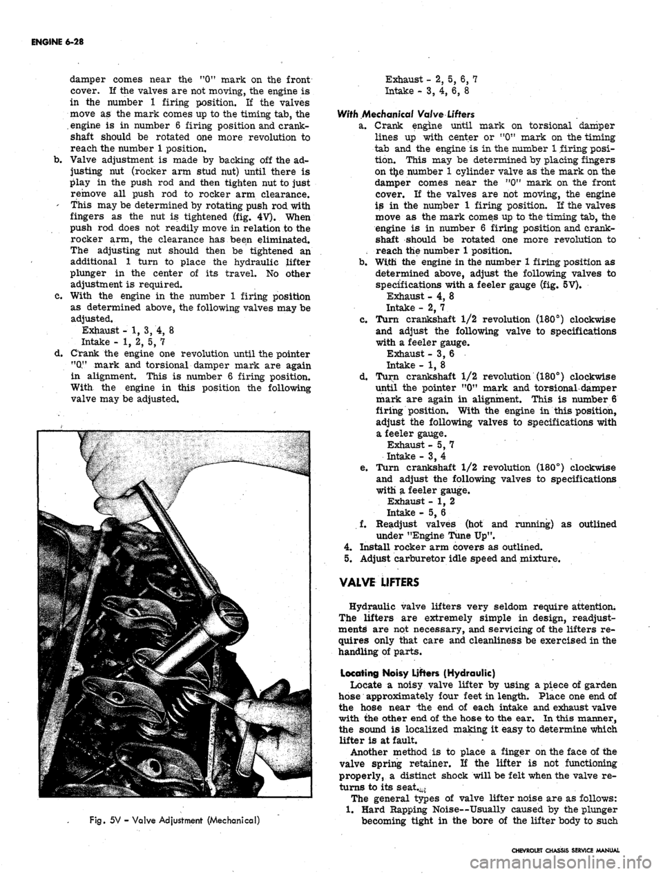
ENGINE 6-28
damper comes near the "0" mark on the front
cover.
11
the valves are not moving, the engine is
in the number 1 firing position. If the valves
move as the mark comes up to the timing tab, the
.
engine is in number 6 firing position and crank-
shaft should be rotated one more revolution to
reach the number 1 position,
b.
Valve adjustment is made by backing off the ad-
justing nut (rocker arm stud nut) until there is
play in the push rod and then tighten nut to just
remove all push rod to rocker arm clearance.
' this may be determined by rotating push rod with
fingers as the nut is tightened (fig. 4
V).
When
push rod does not readily move in relation to the
rocker arm, the clearance has been eliminated.
The adjusting nut should then be tightened an
additional 1 turn to place the hydraulic lifter
plunger in the center of its travel. No other
adjustment is required.
c. With the engine in the number 1 firing position
as determined above, the following valves may be
adjusted.
Exhaust - 1, 3, 4, 8
Intake - 1, 2, 5, 7
d. Crank the engine one revolution until the pointer
"(X" mark and torsional damper mark are again
in alignment. This is number 6 firing position.
With the engine in this position the following
valve may be adjusted.
Fig.
5V - Valve Adjustment (Mechanical)
Exhaust - 2, 5, 6, 7
Intake
-•
3, 4, 6, 8
With Mechanical Valve
Lifters
a. Crank engine until mark on torsional damper
lines up with center or "0" mark on the timing
tab and the engine is in the number 1 firing posi-
tion. This may be determined by placing fingers
on t£e number 1 cylinder valve as the mark on the
damper comes near the n0" mark on the front
cover. If the valves are not moving, the engine
is in the number 1 firing position. If the valves
move as the mark comes up to the timing tab, the
engine is in number 6 firing position and crank-
shaft should be rotated one more revolution to
reach the number 1 position.
b.
With the engine in the number 1 firing position as
determined above, adjust the following valves to
specifications with a feeler gauge (fig. 5V).
Exhaust - 4, 8
Intake - 2, 7. .
c. Turn crankshaft 1/2 revolution (180°) clockwise
and adjust the following valve to specifications
with a feeler gauge.
Exhaust -3,6
Intake - 1, 8
d. Turn crankshaft 1/2 revolution (180°) clockwise
until the pointer "0" mark and torsional-damper
mark are again in alignment. This is number 6
firing position. With the engine in this position,
adjust the following valves to specifications with
a feeler gauge.
Exhaust -5,7
Intake - 3, 4
e. Turn crankshaft 1/2 revolution (180°) clockwise
and adjust the following valves to specifications
with a feeler gauge.
Exhaust - 1, 2
Intake - 5, 6
f. Readjust valves (hot and running) as outlined
under "Engine Tune Up".
4.
Install rocker arm covers as outlined.
5.
Adjust carburetor idle speed and mixture.
VALVE LIFTERS
Hydraulic valve lifters very seldom require attention;
The lifters are extremely simple in design, readjust-
ments are not necessary, and servicing of the lifters re-
quires only that care and cleanliness be exercised in the
handling of parts.
Locating Noisy Lifters (Hydraulic)
Locate a noisy valve lifter by using a piece of garden
hose approximately four feet in length. Place one end of
the hose near the end of each intake and exhaust valve
with the other end of the hose to the ear. In this manner,
the sound is localized making it easy to determine which
lifter is at fault.
Another method is to place a finger on the face of the
valve spring retainer. If the lifter is not functioning
properly, a distinct shock will be felt when the valve re-
turns to its seat.-*
The general types of valve lifter noise are as follows:
1.
Hard Rapping Noise—Usually caused by the plunger
becoming tight in the bore of the lifter body to such
CHEVROLET CHASSIS SERVICE MANUAL
Page 294 of 659
ENGINE 6-29
an extent that the return spring can no longer push
the plunger back up to working position. Probable
causes are:
a. Excessive varnish or carbon deposit causing ab-
normal stickiness.
b.
(Sailing or "pick-up" between plunger and bore of
lifter body, usually caused by an abrasive piece of
dirt or metal wedging between plunger and lifter
body.
2.
Moderate Rapping Noise--Probable causes are:
a. Excessively high leakdown rate.
b.
Leaky check valve seat.
c. Improper adjustment.
3.
General Noise Throughout the Valve Train-rThis
will, in almost all cases, be a definite indication of
insufficient oil supply, or improper adjustment.
4.
Intermittent Clicking—Probable causes are:
a. A microscopic piece of dirt momentarily caught
between ball seat and check valve ball.
b.
In rare cases, the ball itself may be out-of-round
or have a flat spot.
c. Improper adjustment.
In most cases where noise exists in one or more lifters
all lifter units should be removed, disassembled, cleaned
in a solvent, reassembled, and reinstalled in the engine.
If dirt, corrosion, carbon, etc. is shown to exist in one
unit, it more than likely exists in all the units, thus it
would only be a matter of time before all lifters caused
trouble.
Removal
1.
Remove intake manifold as outlined.
2.
Remove valve mechanism as outlined.
3.
Remove valve lifters.
NOTE: Place valve lifters in a rack so they
may be reinstalled in the same location.
Installation
1.
Install valve lifters.
NOTE: Whenever new valve lifters are being
installed coat foot of valve lifters with Molykote
or its equivalent.
2.
Install intake manifold as outlined.
3.
Install and adjust valve mechanism as outlined.
VALVE STEM OIL SEAL AND/OR VALVE SPRING
Replacement
1.
Remove rocker arm cover(s) as outlined.
2.
Remove spark plug, rocker arm and push rod on the
cylinders to be serviced.
3.
Apply compressed air to the spark plug hole to hold
tl*e valves in place.
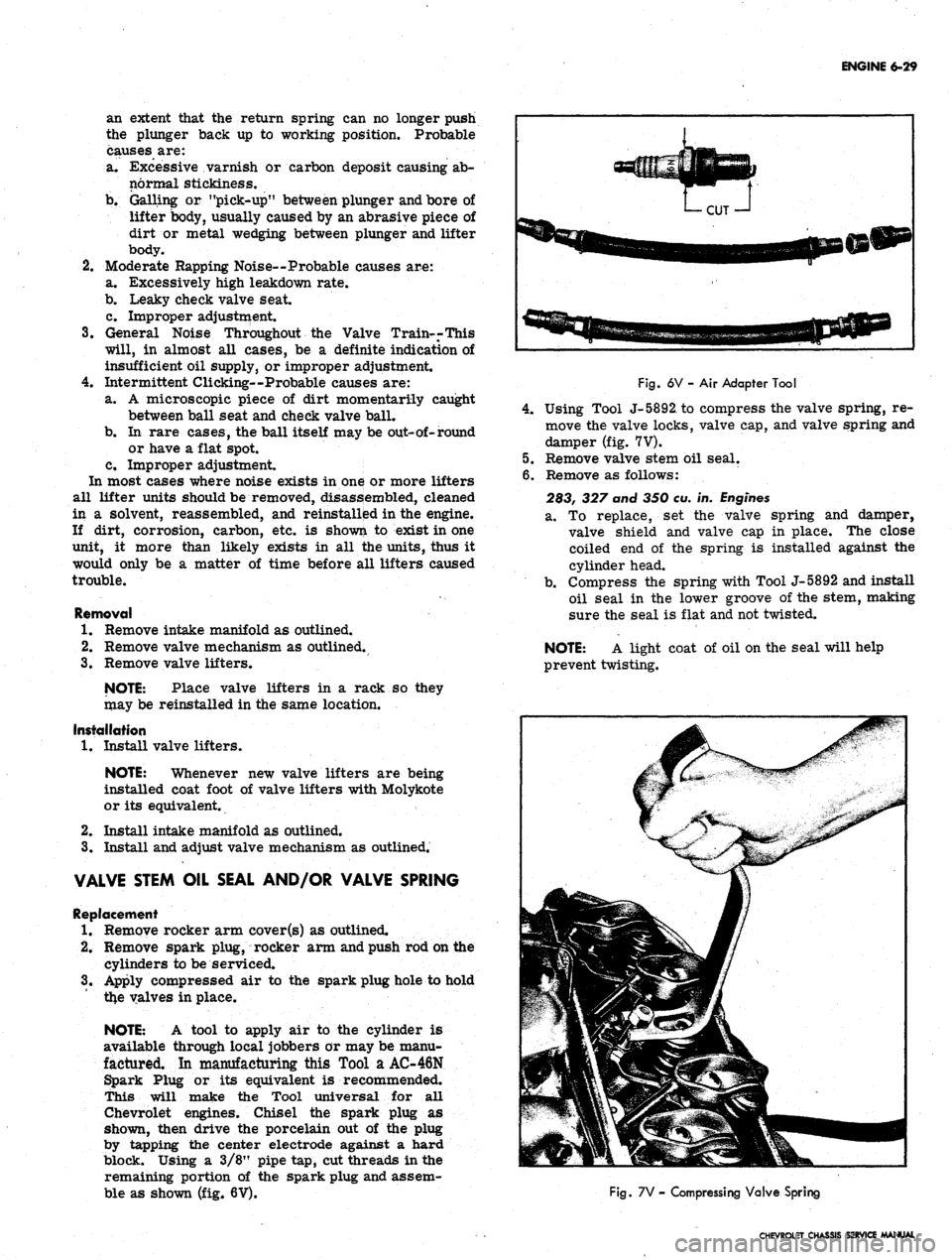
NOTE: A tool to apply air to the cylinder is
available through local jobbers or may be manu-
factured. In manufacturing this Tool a AC-46N
Spark Plug or its equivalent is recommended.
This will make the Tool universal for all
Chevrolet engines. Chisel the spark plug as
shown, then drive the porcelain out of the plug
by tapping the center electrode against a hard
block. Using a 3/8" pipe tap, cut threads in the
remaining portion of the spark plug and assem-
ble as shown (fig. 6V).
Fig.
6V - Air Adapter Tool
4.
Using Tool J-5892, to compress the valve spring, re-
move the valve locks, valve cap, and valve spring and
damper (fig. 7V).
5.
Remove valve stem oil seal.
6. Remove as follows:
283, 327 and 350 eu. in.
Engines
a. To replace, set the valve spring and damper,
valve shield and valve cap in place. The close
coiled end of the spring is installed against the
cylinder head.
b.
Compress the spring with Tool J-5892 and install
oil seal in the lower groove of the stem, making
sure the seal is flat and not twisted.
NOTE: A light coat of oil on the seal will help
prevent twisting.
Fig.
7V - Compressing Valve Spring
CHEVROLET CHASSIS SERVICE MANUAL