seat adjustment CHEVROLET CAMARO 1967 1.G Chassis Owner's Manual
[x] Cancel search | Manufacturer: CHEVROLET, Model Year: 1967, Model line: CAMARO, Model: CHEVROLET CAMARO 1967 1.GPages: 659, PDF Size: 114.24 MB
Page 306 of 659
SECTION 6K
ENGINE COOLING
INDEX
Page
General Description . . . 6K-1
Maintenance and Adjustments 6K-1
Coolant Level 6K-1
Coolant System Checks 6K-1
Periodic Maintenance 6K-2
Cleaning 6K-2
Reverse Flushing 6K-2
Radiator 6K-2
Page
Cylinder Block and Cylinder Head 6K-2
Hot Water Heater 6K-2
Fan Belt . 6K-2
Adjustment ....". 6K-2
Thermostat . 6K-2
Replacement 6K-2
Water Pump. . . . 6K-3
Removal 6K-3
Installation 6K-3
GENERAL DESCRIPTION
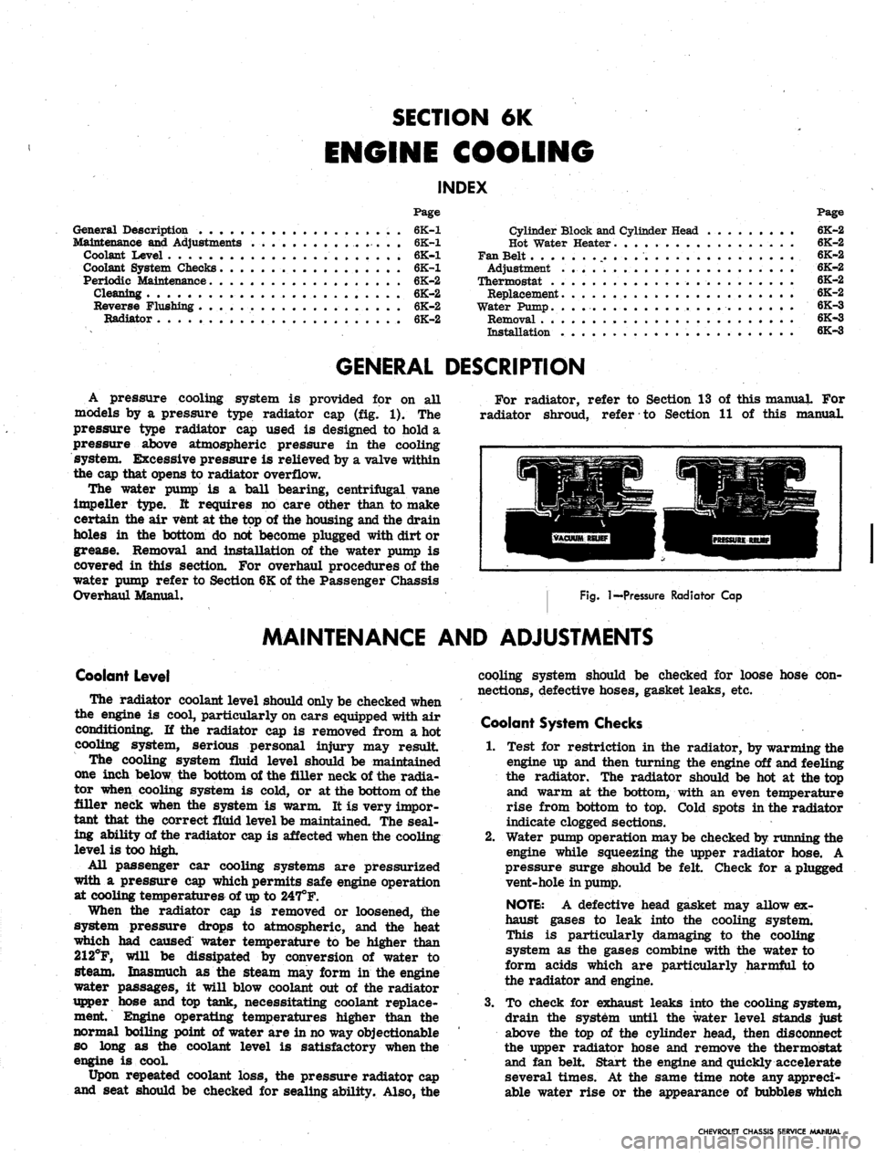
A pressure cooling system is provided for on all
models by a pressure type radiator cap (fig. 1). The
pressure type radiator cap used is designed to hold a
pressure above atmospheric pressure in the cooling
system. Excessive pressure is relieved by a valve within
the cap that opens to radiator overflow.
The water pump is a ball bearing, centrifugal vane
impeller type. It requires no care other than to make
certain the air vent at the top of the housing and the drain
holes in the bottom do not become plugged with dirt or
grease. Removal and installation of the water pump is
covered in this section. For overhaul procedures of the
water pump refer to Section 6K of the Passenger Chassis
Overhaul Manual.
For radiator, refer to Section 13 of this manual For
radiator shroud, refer to Section 11 of this manual.
Fig.
I—Pressure Radiator Cap
MAINTENANCE AND ADJUSTMENTS
Coolant Level
The radiator coolant level should only be checked when
the engine is cool, particularly on cars equipped with air
conditioning. If the radiator cap is removed from a hot
cooling system, serious personal injury may result
The cooling system fluid level should be maintained
one inch below the bottom of the filler neck of the radia-
tor when cooling system is cold, or at the bottom of the
filler neck when the system is warm. It is very impor-
tant that the correct fluid level be maintained. The seal-
ing ability of the radiator cap is affected when the cooling
level is too high.
All passenger car cooling systems are pressurized
with a pressure cap which permits safe engine operation
at cooling temperatures of
up
to 247°F.
When the radiator cap is removed or loosened, the
system pressure drops to atmospheric, and the heat
which had caused water temperature to be higher than
212°F, will be dissipated by conversion of water to
steam. Inasmuch as the steam may form in the engine
water passages, it will blow coolant out of the radiator
upper hose and top tank, necessitating coolant replace-
ment Engine operating temperatures higher than the
normal boiling point of water are in no way objectionable
so long as the coolant level is satisfactory when the
engine is cooL
Upon repeated coolant loss, the pressure radiator cap
and seat should be checked for sealing ability. Also, the
cooling system should be checked for loose hose con-
nections, defective hoses, gasket leaks, etc.
Coolant System Checks
1.
Test for restriction in the radiator, by warming the
engine up and then turning the engine off and feeling
the radiator. The radiator should be hot at the top
and warm at the bottom, with an even temperature
rise from bottom to top. Cold spots in the radiator
indicate clogged sections.
2.
Water pump operation may be checked by running the
engine while squeezing the upper radiator hose. A
pressure surge should be felt Check for a plugged
vent-hole in pump.
NOTE:
A defective head gasket may allow ex-
haust gases to leak into the cooling system.
This is particularly damaging to the cooling
system as the gases combine with the water to
form acids which are particularly harmful to
the radiator and engine.
3.
To check for exhaust leaks into the cooling system,
drain the system until the water level stands just
above the top of the cylinder head, then disconnect
the upper radiator hose and remove the thermostat
and fan belt. Start the engine and quickly accelerate
several times. At the same time note any appreci-
able water rise or the appearance of bubbles which
CHEVROLET CHASSIS SERVICE MANUAL
Page 309 of 659

SECTION 6M
ENGINE FUEL
CONTENTS OF THIS SECTION
Page
Carburetors 6M-1 Fuel Pumps .
Air Cleaners 6M-7 Special Tools
Page
6M-10
6M-12
CARBURETORS
INDEX
Page
General Description 6M-1
Service Procedures 6M-1
Preliminary Checks 6M-1
Idle Speed and Mixture Adjustment ........... 6M-1
Fast Idle Adjustment .................. 6M-3
Choke Adjustment 6M-3
Float Adjustment 6M-4
Page
Additional Adjustments 6M-4
Removal 6M-4
Test Before Installation 6M-5
Installation 6M-5
Fuel Filter Maintenance 6M-5
Choke Coil Replacement 6M-5
Throttle Linkage Adjustment . . 6M-6
GENERAL DESCRIPTION
Various carburetors (fig. lc) are used with Chevrolet,
Chevelle, Chevy II, Camaro and Corvette passenger
vehicles. These carburetors are designed to meet the
particular requirements of engines, transmissions and
vehicles, therefore carburetors that look alike are not
always interchangeable. (Refer to carburetor part num-
ber and/or specifications.)
Because many service procedures for the various
carburetors are similar, typical illustrations and pro-
cedures are used except where specific illustrations or
procedures are necessary to clarify the operation.
This section covers removal, installation and adjust-
ments (on engine) of carburetors. Also covered in this
section are maintenance procedures for choke coils,
throttle linkage and fuel filters. For carburetor .over-
haul procedures and additional adjustments (bench), re-
fer to Section 6M of the Overhaul Manual under the
carburetor being serviced.
Specifications for carburetors are located in the back
of this manual.
SERVICE PROCEDURES
Preliminary Checks
1.
Thoroughly warm-up engine. If the engine is cold,
allow to run for at least 15 minutes.
2.
Inspect torque of carburetor to intake manifold bolts
and intake manifold to cylinder head bolts to exclude
the possibility of air leaks.
3.
Inspect manifold heat control valve (if used) for free-
dom of action and correct spring tension.
Idle Speed and Mixture Adjustment (Except Air Injection
Reactor System)
NOTE:
This adjustment should be performed
with engine at operating temperature and park-
ing brake applied.
1.
Remove Air Cleaner.
2.
Connect tachometer and vacuum gauge to engine, then
set hand brake and shift transmission into neutral.
3.
As a preliminary adjustment, turn idle mixture
screws lightly to seat and back out 1-1/2 turns.
CAUTION: Do not turn idle mixture screw
tightly against seat or damage may result.
4.
With engine running (choke wide open) adjust idle
speed screw to specified idle speed, (automatic
transmission in drive, synchronized transmission in
neutral).
5. Adjust idle mixture screw to obtain highest steady
vacuum at specified idle speed.
NOTE:
On air conditioned vehicles, turn air
conditioning to the "on" position and hold the
hot idle compensator valve closed while adjust-
ing idle speed and idle mixture screws.
NOTE:
On Rochester BV carburetors the idle
mixture screw should be turned out 1/4 turn
from the "lean roll" position. The definition
of "lean roll" point is a 20 to 30 rpm drop
in engine speed obtained by leaning the idle
mixture.
6. Repeat Steps 4 and5 as needed for final adjustment.
NOTE:
If necessary, final adjustment of the \
carburetor may be made with the air cleaner
installed.
7. Turn engine off, remove gauges and install air
clearer.
CHEVROLET CHASSIS SERVICE MANUAL
Page 311 of 659

ENGINE FUEL 6M-3
Idle Speed and Mixture Adjustment (With Air Injection
Reactor System)
The following is the recommended procedure for Air
Injection Reactor System equipped engines.
NOTE: This adjustment should be performed
with engine at operating temperature and parking
brake applied.
1.
Remove air cleaner.
2.
Connect tachometer to engine, then set hand brake
and shift transmission into neutral.
3.
As a preliminary adjustment, turn idle mixture
screws lightly to seat and back out 3 turns.
CAUTION: Do not turn idle mixture screw
tightly against seat or damage may result."
4.
With engine running (choke wide open) adjust idle
speed screw to specified idle speed. (Automatic
transmission in dirve, synchronized transmission in
neutral).
5.
Adjust idle mixture screw (turn in) to "lean roll"
position; then turn screw out 1/4 turn (1/4 turn
rich from "lean roll"). The definition of "lean
roll" point is a 20 to 30 rpm drop in engine speed,
obtained by leaning the idle mixture.
NOTE: On air conditioned vehicles, turn air
conditioning "OFF" on in-line, 283, 327, and'
350 cu. in. engines, and turned "ON" and hot
idle compensator held closed on 396 and 427 cu.
in. engines.
6. Repeat Steps 4 and 5 as needed for final adjustment.
NOTE: If necessary, final adjustment of the
carburetor may be made with air cleaner
installed.
7.
Shut down the engine, remove gauges and install air
cleaner. *
Fast Idle Adjustment
Rochester
4MV and Holley
With fast idle lever on high step of cam and choke valve
open (engine warm) set fast idle to give specified engine
rpm. Adjust sejrew on Rochester 4MV and bend fast
idle lever *pn Holley. .
Choke Adjustment
With Remote Choke (Fig. 2c)
1.
Remove air cleaner and check to see that choke
valve and rod move freely.
2.
Disconnect choke rod at choke lever.
3.
Check choke adjustment as follows:
On all except 275 and 300 h.p. 327 cu. in. engines,
hold choke valve closed and pull.rod up against stop.
The top of choke rod end should be 1/2-1 rod diame-
ter above top of hole in choke valve lever.
On 275 and 300 h.p. 327 cu. in. engines, hold choke
valve closed and push rod down against stop on ther-
mostat bracket. The top of the choke rod should be
1/2-1 rod diameter below the top of the hole in the
choke lever.
4.
If necessary, adjust rod length by bending rod at
offset bend. (Bend must be such that rod enters
choke lever hole freely and squarely).
5.
Connect rod at choke lever and install air cleaner.
With Manual Choke (Carter YF)
1.
Remove air cleaner.
CHOKE VALVE
COMPLETELY
CLOSED
PULL UPWARD ON
ROD TO END OF
TRAVEL
BEND ROD
TO ADJUST
ROD IN BOTTOM
OF SLOT
BOTTOM OF
ROD SHOULD
BE EVEN WITH
TOP OF
HOLE
CHOKE VALVE
CLOSED
BOTTOM OF
ROD SHOULD
BE EVEN WITH
TOP OF HOLE
TOP OF ROD
SHOULD BE EVEN
WITH BOTTOM
OF HOLE (CHOKE
CLOSED)
BEND ROD TO
ADJUST
PULL DOWNWARD'
ON ROD TO CON-
TACT STOP
L6 (TYPICAL)
[
V8 327-275 HP
V8 350-295 HP
BEND ROD
TO ADJUST
PULL UPWARD ON
ROD TO CONTACT
STOP ON BRACKET
ALL V8 (EXCEPT 327-275 HP
AND 350-295 HP)
Fig.
2C—Remote Choke Adjustment
CHEVROLET CHASSIS SERVICE MANUAL
Page 361 of 659
CLUTCH AND TRANSMISSIONS 7-2
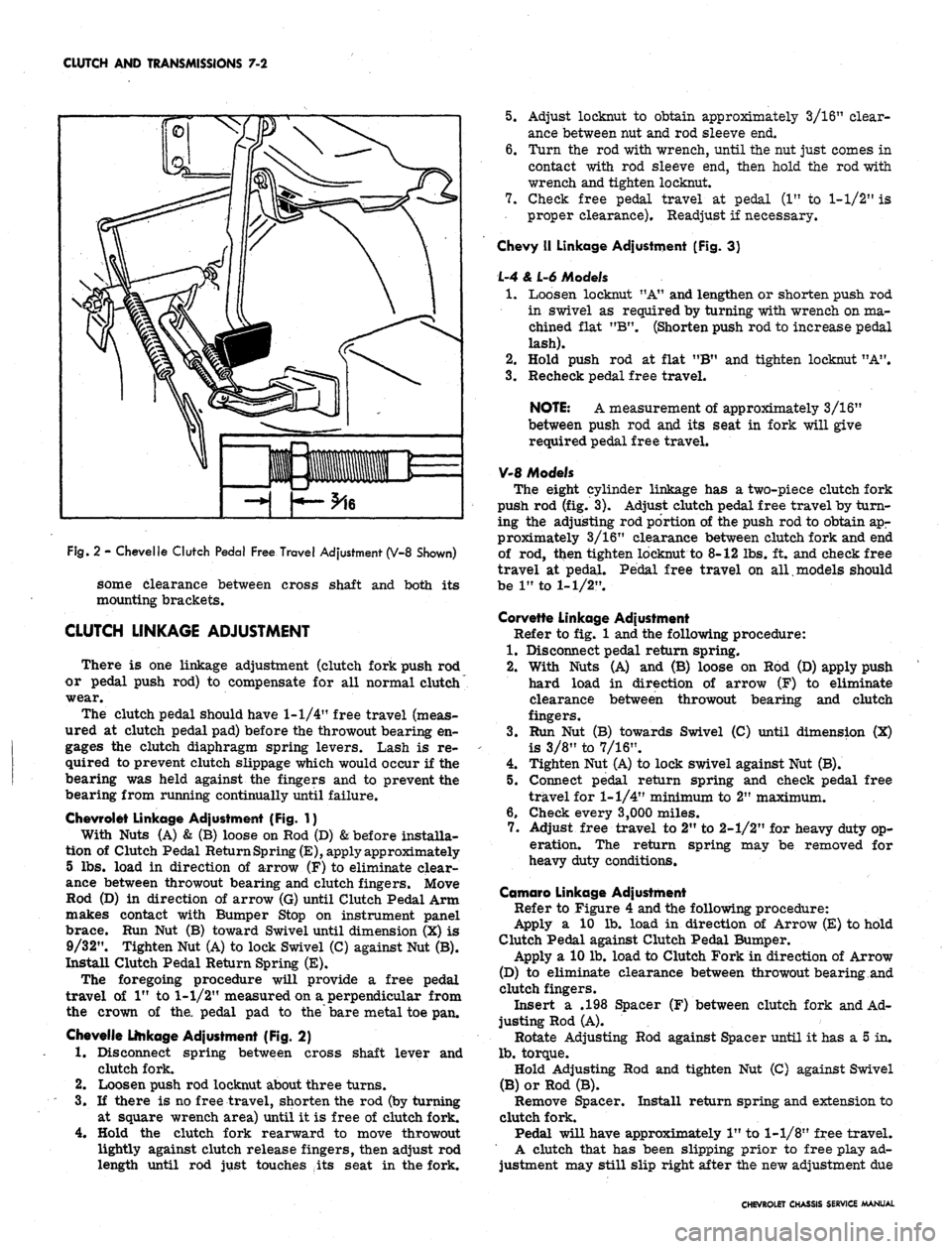
Fig.
2 - Chevelle Clutch Pedal Free Travel Adjustment (V-8 Shown)
some clearance between cross shaft and both its
mounting brackets.
CLUTCH LINKAGE ADJUSTMENT
There is one linkage adjustment (clutch fork push rod
or pedal push rod) to compensate for all normal clutch
wear.
The clutch pedal should have
1-1/4"
free travel (meas-
ured at clutch pedal pad) before the throwout bearing en-
gages the clutch diaphragm spring levers. Lash is re-
quired to prevent clutch slippage which would occur if the
bearing was held against the fingers and to prevent the
bearing from running continually until failure.
Chevrolet Linkage Adjustment (Fig. 1}
With Nuts (A) & (B) loose on Rod (D)
&
before installa-
tion of Clutch Pedal Return Spring
(E),
apply approximately
5 lbs. load in direction of arrow (F) to eliminate clear-
ance between throwout bearing and clutch fingers. Move
Rod (D) in direction of arrow (G) until Clutch Pedal Arm
makes contact with Bumper Stop on instrument panel
brace. Run Nut (B) toward Swivel until dimension (X) is
9/32". Tighten Nut (A) to lock Swivel (C) against Nut (B).
Install Clutch Pedal Return Spring (E).
The foregoing procedure will provide a free pedal
travel of 1" to
1-1/2"
measured on a perpendicular from
the crown of the, pedal pad to the bare metal toe pan.
Chevelle Linkage Adjustment (Fig. 2)
1.
Disconnect spring between cross shaft lever and
clutch fork.
2.
Loosen push rod locknut about three turns.
3.
If there is no free travel, shorten the rod (by turning
at square wrench area) until it is free of clutch fork.
4.
Hold the clutch fork rearward to move throwout
lightly against clutch release fingers, then adjust rod
length until rod just touches ,its seat in the fork.
5.
Adjust locknut to obtain approximately 3/16" clear-
ance between nut and rod sleeve end.
6. Turn the rod with wrench, until the nut just comes in
contact with rod sleeve end, then hold the rod with
wrench and tighten locknut.
7.
Check free pedal travel at pedal (1" to
1-1/2"
is
proper clearance). Readjust if necessary.
Chevy II Linkage Adjustment (Fig. 3}
L-4 & L-6 Models
1.
Loosen locknut "A" and lengthen or shorten push rod
in swivel as required by turning with wrench on ma-
chined flat "B". (Shorten push rod to increase pedal
lash).
2.
Hold push rod at flat "B" and tighten locknut "A".
3.
Recheck pedal free travel.
NOTE: A measurement of approximately 3/16"
between push rod and its seat in fork will give
required pedal free travel.
V-8 Models
The eight cylinder linkage has a two-piece clutch fork
push rod (fig. 3). Adjust clutch pedal free travel by turn-
ing the adjusting rod portion of the push rod to obtain apr
proximately 3/16" clearance between clutch fork and end
of rod, ttien tighten locknut to 8-12 lbs. ft. and check free
travel at pedal. Pedal free travel on all models should
be 1" to
1-1/2".
Corvette Linkage Adjustment
Refer to fig. 1 and the following procedure:
1.
Disconnect pedal return spring.
2.
With Nuts (A) and (B) loose on Rod (D) apply push
hard load in direction of arrow (F) to eliminate
clearance between throwout bearing and clutch
fingers.
3.
Run Nut (B) towards Swivel (C) until dimension (X)
is 3/8" to 7/16".
4.
Tighten Nut (A) to lock swivel against Nut (B).
5.
Connect pedal return spring and check pedal free
travel for
1-1/4"
minimum to 2" maximum.
6. Check every 3,000 miles.
7.
Adjust free travel to 2" to 2-1/2" for heavy duty op-
eration. The return spring may be removed for
heavy duty conditions.
Camaro Linkage Adjustment
Refer to Figure 4 and the following procedure:
Apply a 10 lb. load in direction of Arrow (E) to hold
Clutch Pedal against Clutch Pedal Bumper.
Apply a 10 lb. load to Clutch Fork in direction of Arrow
(D) to eliminate clearance between throwout bearing and
clutch fingers.
Insert a .198 Spacer (F) between clutch fork and Ad-
justing Rod (A).
Rotate Adjusting Rod against Spacer until it has a 5 in.
lb.
torque.
Hold Adjusting Rod and tighten Nut (C) against Swivel
(B) or Rod (B).
Remove Spacer. Install return spring and extension to
clutch fork.
Pedal will have approximately 1" to
1-1/8"
free travel.
A clutch that has been slipping prior to free play ad-
justment may still slip right after the new adjustment due
CHEVROLET CHASSIS SERVICE MANUAL
Page 363 of 659
CLUTCH AND TRANSMISSIONS 7-4
5.
Install Tool J-5824 to support the clutch assembly
during removal.
NOTE: Look for "X" mark on flywheel and on
clutch cover. If MX" mark is not evident, prick
punch marks on flywheel and clutch cover for
indexing purposes during installation.
6. Loosen the clutch-to-flywheel attaching bolts evenly
1 turn at a time until spring pressure is released,
then remove the bolts, and remove clutch assembly.
Installation to Vehicle
Clean pressure plate and flywheel face. (They should
be free of oil, grease, metal deposits or burned spots).
1.
Position the clutch disc and pressure plate in relar
tive installed position and support them with align-
ment Tool J-5824.
NOTE: The driven disc on the 4 and 6 cylinder
engines is installed with the damfper springs to
the flywheel side; the V-8 is opposite, however,
THE GREASE SLINGER IS ALWAYS ON THE
TRANSMISSION SIDE.
2.
Turn clutch assembly until "X" mark on cover lines
up with "X" mark oh flywheel, then align cover bolt
holes to nearest flywheel holes.
3.
Install a bolt in every hole and tighten down evenly
and gradually until tight (to avoid possible clutch
distortion).
NOTE: Cover loads are as high as 1-1/4 tons.
4.
Remove pilot tool.
5.
Unhook clutch fork and lubricate ball socket and fork
fingers at release bearing end with a high melting
point grease such as graphite and reinstall fork on
ball stud. On Corvette models use Moly Grease.
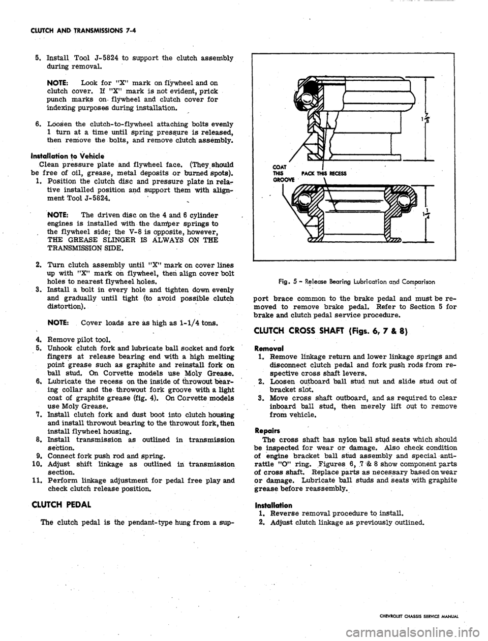
6. Lubricate the recess on the inside of throwout bear-
ing collar and the throwout fork groove with a light
coat of graphite grease (fig. 4). On Corvette models
use Moly Grease.
7.
Install clutch fork and dust boot into clutch housing
and install throwout bearing to the throwout fork, then
install flywheel housing.
8. Install transmission as outlined in transmission
section.
9. Connect fork push rod and spring.
10.
Adjust shift linkage as outlined in transmission
section.
11.
Perform linkage adjustment for pedal free play and
check clutch release position.
CLUTCH PEDAL
The clutch pedal is the pendant-type hung from a sup-
Fig. 5 - Release Bearing Lubrication and Comparison
port brace common to the brake pedal and must be re-
moved to remove brake pedal. Refer to Section 5 for
brake and clutch pedal service procedure.
CLUTCH CROSS SHAFT (Figs. 6, 7 & 8)
Removal
1.
Remove linkage return and lower linkage springs and
disconnect clutch pedal and fork push rods from re-
spective cross shaft levers.
2.
Loosen outboard ball stud nut and slide stud out of
bracket slot.
3.
Move cross shaft outboard, and as required to clear
inboard ball stud, then merely lift out to remove
from vehicle.
Repairs
The cross shaft has nylon ball stud seats which should
be inspected for wear or damage. Also check condition
of engine bracket ball stud assembly and special anti-
rattle "O" ring. Figures 6, .7
&
8 show component parts
of cross shaft. Replace parts as necessary based on wear
or damage. Lubricate ball studs and seats with graphite
grease before reassembly.
Installation
1.
Reverse removal procedure to install.
2.
Adjust clutch linkage as previously outlined.
CHEVROLET CHASSIS SERVICE MANUAL
Page 376 of 659
CLUTCH AND TRANSMISSIONS 7-17
VIEW A
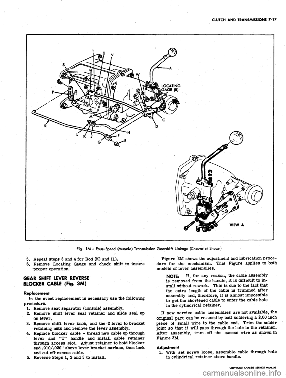
Fig.
1M - Four-Speed (Muncie) Transmission Gearshift Linkage (Chevrolet Shown)
5.
Repeat steps 3 and 4 for Hod (K) and (L).
6. Remove Locating Gauge and check shift to insure
proper operation.
GEAR SHIFT LEVER REVERSE
BLOCKER CABLE (Fig. 3M)
Replacement
In the event replacement is necessary use the following
procedure.
1.
Remove seat separator (console) assembly.
2.
Remove shift lever seal retainer and slide seal up
on lever.
3.
Remove shift lever knob, and the 2 lever to bracket
retaining nuts and remove the lever assembly.
4.
Replace blocker cable - thread new cable up through
lever and MT" handle and install cable retainer
through access slot. Adjust retainer to hold blocker
end .010/.020" above lever bracket surface, then lock
and cut off excess cable.
5.
Reverse Steps 1, 2 and 3 to install.
Figure 3M shows the adjustment and lubrication proce-
dure for the mechanism. This Figure applies to both
models of lever assemblies.
NOTE: If, for any reason, the cable assembly
is removed from the handle, it is difficult to in-
stall without rework. This is due to the fact that
the extra length of the cable is trimmed after
assembly and, therefore, it is almost impossible
to get the shortened cable to enter the cable hole
in the cylindrical retainer.
If new service cable assemblies are not available, the
original part can be re-used by butt soldering a 2.00 inch
piece of small wire to the cable end. Trim the solder
joint so that it will pass through the hole in the retainer.
After assembly, trim off the excess wire as shown in
Figure 3M.
Adjustment
1.
With set screw loose, assemble cable through hole
in cylindrical retainer above handle.
CHEVROLET CHASSIS SERVICE MANUAL
Page 382 of 659
CLUTCH
AND
TRANSMISSIONS
7-23
Assembly (Fig.
4X)
1.
With detent spring tang projecting
up
over
the 3rd
and
4th
shifter shaft cover opening install
the
first
and second detent
cam
onto
the
detent
cam
pivot
pin.
With
the
detent spring tang projecting
up
over
the
first
and
second shifter shaft cover hole install
the
3rd
and 4th
detent
cam,
NOTE:
The 1-2
detent
cam has a
.090" greater
contour
on the
inside detent notch.
2.
3.
Install detent
cam
retaining
"C"
ring
to
pivot shaft,
and hook spring into detent
cam
notches.
Install
1-2 and 3-4
shifter shaft assemblies
in
cover
being careful
not to
damage seals. Install both shift
forks
to
shifter shaft assemblies, lifting
up on
detent
cam
to
allow forks
to
fully seat into position.
4.
Install reverse detent ball
and
spring
to
cover, then
install reverse shifter shaft assembly
to
cover.
5.
Install outer shifter levers, flat washers, lock wash-
ers
and
bolts.
Installation
1.
Shift shifter levers into neutral detent (center) posi-
tion. Position cover gasket
on
case.
2.
Carefully position side cover into place making sure
the shift forks
are
aligned with their respective
mainshaft clutch sliding sleeves.
Install cover attaching bolts
and
tighten evenly
to
specified torque.
Remove filler plug
and add
lubricant specified
in
Section
0, to
level
of
filler plug hole.
3.
4.
ALUMINUM POWERGLIDE
INDEX
Page
General
Description
7-23
Maintenance
and
Adjustments .............. 7—23
Oil
Level Check
7-23
Periodic
Oil
Change
7-24
Periodic
Low
Band Adjustment
7-24
Manual
Shift Linkage Check
and
Adjust
7-24
Floor
Shift Linkage
7-25
Floor
Mounted Control Lever
and
Bracket
Assembly
7-29
Throttle
Valve Linkage
.... 7-29
Neutral
Safety Switch
.. . 7-30
Throttle
Return Check Valve (Dashpot)
7-30
Component
Parts Replacement
7-30
Transmission
Replacement .............. 7—30
Page
Other
Service Operations
7-32
Diagnosis
7-32
Warming
Up
Transmission
7-32
Shop
Warm
Up , 7-32
Road
Warm
Up 7-32
Checking
Fluid Level
and
Condition
7-32
Manual
Linkage
7-32
Oil
Leaks
7-33
Basic
Pressure Checks
7-33
Wide
Open Throttle Upshift Pressure Check
.... 7-33
Idle
Pressure
in
Drive Range
7-33
Manual
"Low"
Range Pressure Check .......
7-33
Drive
Range Overrun (Coast) Pressure
.
.......
7-33
Powerglide
Shift Points
. . 7-35
GENERAL DESCRIPTION
The case
and
converter housing
of the two
speed alumi-
num Powerglide Transmission
is a
single case aluminum
unit. When
the
manual control
is
placed
in the
drive
po-
sition,
the
transmission automatically shifts
to low
gear
for initial vehicle movement.
As the car
gains speed
and
depending
on
load
and
throttle position,
an
automatic shift
is made
to
high gear.
A
forced downshift feature
pro-
vides
a
passing gear
by
returning
the
transmission
to low
range.
The
oil
pump assembly
is a
conventional gear type
and
the
oil
pump housing
is of the
large diameter type acting
as
the
front bulkhead
of the
transmission.
The
torque
converter
is a
conventional three element welded design
bolted
to the
engine flywheel which drives through
a
two-
speed planetary gearset.
The
high clutch assembly
is
typical
of the
designs used
in
this type transmission.
The
aluminum Powerglide uses
an
output shaft mounted
gov-
ernor which requires
a
hole through
the
output shaft.
The
reverse clutch assembly
is a
multiple disc type clutch.
The steel plates
are
splined directly
to the
case while
the
face plates
are
splined
to the
internal
or
ring gear.
The
clutch piston operates within
the
rear portion
of the
case.
The internal diameter
of the
pistoh
is
sealed to
an
integral
hub portion
of the
case rear bulkhead.
The
outside
dia-
meter
is
sealed
to a
machined portion
of the
case.
The
piston
is
hydraulically applied
and is
released
by
separate
coil springs.
The
valve body assembly
is
bolted
to the
bottom
of the
transmission case
and is
accessible
for
service
by
removing
the oil pan
assembly.
The
valve
body consists
of an
upper
and
lower body located
on
either
side
of a
transfer plate.
The
vacuum modulator
is lo-
cated
on the
left rear face
of the
transmission case.
The
modulator valve bore
is
located
in the
upper valve body.
MAINTENANCE
AND
ADJUSTMENTS
OIL LEVEL CHECK
The transmission
oil
level should
be
checked period-
ically
as
recommended
in
Section
0. Oil
should
be
added
only when level
is on or
below
the
"ADD" mark
on the dip
stick with
oil hot or at
operating temperature.
The oil
level
dip
stick
is
located
at the
right rear
of the
engine
compartment. Fill with
oil
specified
in
Section
0.
In order
to
check
oil
level accurately,
the
engine should
be idled with
the
transmission
oil hot and the
control
lever
in
neutral (N) position.
It
is
important that
the oil
level
be
maintained
no
higher than
the
"FULL" mark
on the
transmission
oil
level gauge.
DO NOT
OVERFILL,
for
when
the oil
level
CHEVROLET CHASSIS SERVICE MANUAL
Page 398 of 659
CLUTCH AND TRANSMISSIONS 7-39
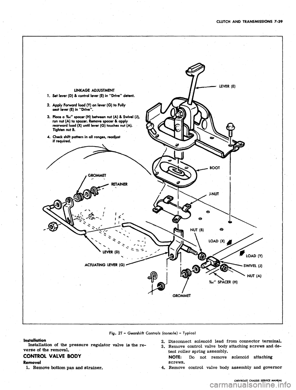
LINKAGE ADJUSTMENT
1.
Set lever (D) & control lever (E) in "Drive" detent.
2.
Apply Forward load (Y) on lever (G) to Fully
seat lever (E) in "Drive".
3. Place a %4" spacer (H) between nut (A) & Swivel (J),
run nut (A) to spacer. Remove spacer & apply
rearward load (X) until lever (G) touches nut (A).
Tighten nut B.
4. Check shift pattern in all ranges, readjust
if required.
LEVER (E)
LEVER (D)
ACTUATING LEVER (G)
LOAD (Y)
SWIVEL (J)
NUT (A)
GROMMET
Fig.
2T - Gearshift Controls (console) - Typical
Installation
Installation of the pressure regulator valve is the re-
verse of the removal.
CONTROL VALVE BODY
Removal
1.
Remove bottom pan and strainer.
2.
Disconnect solenoid lead from connector terminal.
3.
Remove control valve body attaching screws and de-
tent roller spring assembly.
NOTE:
Do not remove solenoid attaching
screws.
4.
Remove control valve body assembly and governor
CHEVROLET CHASSIS SERVICE MANUAL
Page 448 of 659
STEERING 9-8
DIAL
UPPER COVER
FASTENER
CHEVROLET
SCREW
CHEVELLE
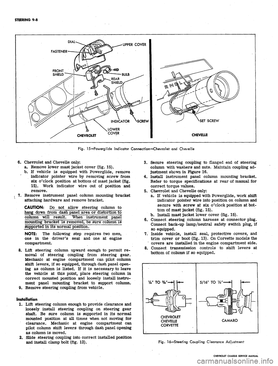
Fig.
15—Powerglide Indicator Connection—Chevrolet and Chevelle
6.
Chevrolet and Chevelle only:
a. Remove lower mast jacket cover (fig. 15).
b.
If vehicle is equipped with Powerglide, remove
indicator pointer wire by removing screw from
six o'clock position at bottom of mast jacket (fig.
15).
Work indicator wire out of position and
remove.
Remove instrument panel column mounting bracket
attaching hardware and remove bracket.
CAUTION: Do not allow steering column to
hang down from dash panel area or distortion to
column will result. When instrument panel
mounting bracket is removed, be sure column is
supported in its normal position.
NOTE:
The following step requires two men,
one in the driver's seat and one at engine
compartment.
8
Lift steering column upward enough to permit re-
moval of steering coupling from steering gear.
Mechanic at engine compartment can pilot column
shift levers, if so equipped, through dash panel open-
ing as column is listed. If it is necessary to leave
the vehicle at this point, place steering column in
correct mounted position and loosely install instru-
ment panel mounting bracket to support column.
9. Remove steering coupling from vehicle.
Installation
1.
Lift steering column enough to provide clearance and
loosely install steering coupling on steering gear
shaft. Be sure column is supported in its normal
mounted position at all times when not moving for
clearance. Mechanic at engine compartment can
pilot column shift levers through dash panel opening
as column is moved.
2.
Slide steering coupling into correct installed position
and install clamp bolt (fig. 12).
3.
Secure steering coupling to flanged end of steering
column with washers and nuts. Maintain coupling ad-
justment shown in Figure 16.
4.
Install instrument panel column mounting bracket.
Refer to torque specifications at rear of manual for
correct torque values.
5. Chevrolet and Chevelle only:
a. If vehicle is equipped with Powerglide, work shift
indicator pointer wire into position on column and
secure with screw at six o'clock position at bot-
tom of mast jacket (fig. 15).
b.
Install mast jacket lower cover (fig. 15).
6. Connect steering column harness at connector plug.
Connect back-up lamp/neutral safety switch plug, if
so equipped.
7. Inside vehicle, install seal, protective covers, and
trim cover or boot (fig. 13). On Corvette models the
' covers are installed in the engine compartment side.
8. Connect transmission controls to shift levers at
bottom of column if so equipped.
CHEVROLET
CHEVELLE
CORVETTE
CAMARO
Fig.
16—Steering Coupling Clearance Adjustment
CHEVROLET CHASSIS SERVICE MANUAL
Page 449 of 659
STEERING 9-9
STEERING GEAR-CHEVROLET, CHEVELLE,
CAMARO, AND CORVETTE (Fig. 12)
Removal
1.
Remove retaining nuts, lock washers, and bolts at
steering coupling. (No bolts are used on Corvette.)
On Corvette, loosen clamp bolt and slide coupling
upper flange upward on steering shaft.
2.
Remove pitman arm nut and washer from sector
shaft and mark relation of arm position to shaft.
3.
Remove pitman arm with Tool J-6632 as shown in
Figure 2.
4.
Chevelle only: . ,
a. Remove stabilizer bar to frame mounting
brackets.
b.
Remove bolt, washer, and nut securing left front
bumper bracket and brace to frame. (See Section
14,
Figure 3.) Scribe a mark around adjustment
washer for position reference, then loosen bolt
at adjustment washer location enough to release
washer from notches in bracket.
NOTE:
On Camaro models, use care not to bend
or fracture brake pipe when removing steering
gear.
5. Remove screws securing steering gear to frame and
remove gear from vehicle.
Installation
1.
Place gear into position so that steering coupling
mounts properly to flanged end of steering shaft.
Secure gear to frame with washers and bolts. On
Corvette models, install gear with bolts, washers,
and nuts. Maintain coupling adjustment shown in
Figure 16.
2.
Chevelle only:
a. Holding front bumper in place, loosely install
bolt, washer, and nut to secure bumper bracket
and brace
to.
frame.
b.
Position .adjustment washer in notches of bumper
bracket' and align washer with mark made during
removal. Tighten mounting bolts.
c. Install stabilizer bar to frame mounting brackets.
Refer to torque specifications at rear of manual
for correct torque values.
3.
Install pitman arm aligning marks made during re-
moval and secure with washer and retaining nut.
4.
Secure steering coupling to flanged end of steering
column with lock washers, and nuts.
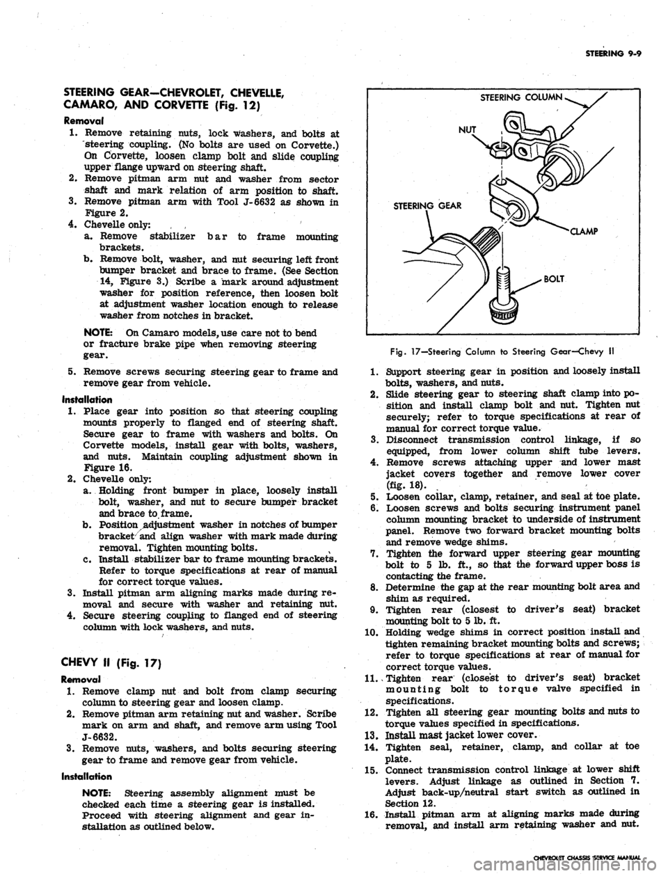
CHEVY II (Fig. 17)
Removal
1.
Remove clamp nut and bolt from clamp securing
column to steering gear and loosen clamp.
2.
Remove pitman arm retaining nut and washer. Scribe
mark on arm and shaft, and remove arm using Tool
J-6632.
3.
Remove nuts, washers, and bolts securing steering
gear to frame and remove gear from vehicle.
Installation
NOTE:
Steering assembly alignment must be
checked each time a steering gear is installed.
Proceed with steering alignment and gear in-
stallation as outlined below.
STEERING COLUMN
NUT
STEERING GEAR
CLAMP
BOLT
Fig.
17—Steering Column to Steering Gear—Chevy II
1.
Support steering gear in position and loosely install
bolts,
washers, and nuts.
2.
Slide steering gear to steering shaft clamp into po-
sition and install clamp bolt and nut. Tighten nut
securely; refer to torque specifications at rear of
manual for correct torque value.
3.
Disconnect transmission control linkage, if so
equipped, from lower column shift tube levers.
4.
Remove screws attaching upper and lower mast
jacket covers together and remove lower cover
(fig. 18).
5. Loosen collar, clamp, retainer, and seal at toe plate.
6. Loosen screws and bolts securing instrument panel
column mounting bracket to underside of instrument
panel. Remove two forward bracket mounting bolts
and remove wedge shims.
7. Tighten the forward upper steering gear mounting
bolt to 5 lb. ft., so that the forward upper boss is
contacting the frame.
8. Determine the gap at the rear mounting bolt area and
shim as required.
9. Tighten rear (closest to driver's seat) bracket
mounting bolt to 5 lb. ft.
10.
Holding wedge shims in correct position install and
tighten remaining bracket mounting bolts and screws;
refer to torque specifications at rear of manual for
correct torque values.
11.
Tighten rear (closest to driver's seat) bracket
mounting bolt to torque valve specified in
specifications.
12.
Tighten all steering gear mounting bolts and nuts to
torque values specified in specifications.
13.
Install mast jacket lower cover.
14.
Tighten seal, retainer, clamp, and collar at toe
plate.
15.
Connect transmission control linkage at lower shift
levers. Adjust linkage as outlined in Section 7.
Adjust back-up/neutral start switch as outlined in
Section 12.
16.
Install pitman arm at aligning marks made during
removal, and install arm retaining washer and nut.
CHEVROLET CHASSIS SERVICE MANUAL