seat adjustment CHEVROLET CAMARO 1967 1.G Chassis Owner's Guide
[x] Cancel search | Manufacturer: CHEVROLET, Model Year: 1967, Model line: CAMARO, Model: CHEVROLET CAMARO 1967 1.GPages: 659, PDF Size: 114.24 MB
Page 457 of 659
STEERING 9-17
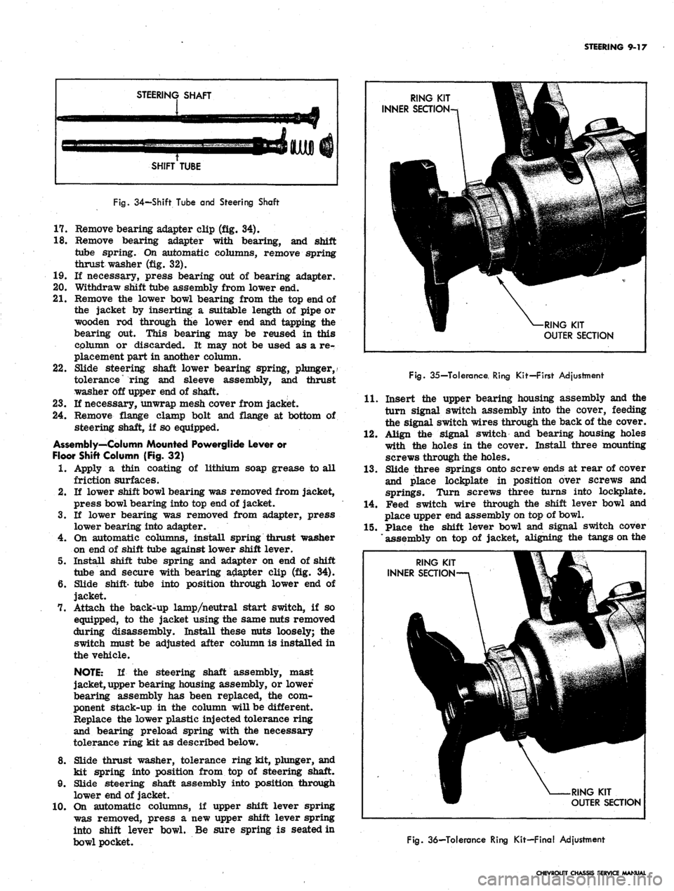
STEERING SHAFT
SHIFT TUBE
Fig.
34—Shift Tube and Steering Shaft
17.
Remove bearing adapter clip (fig. 34).
18.
Remove bearing adapter with bearing, and shift
tube spring. On automatic columns, remove spring
thrust washer (fig. 32).
19.
U necessary, press bearing out of bearing adapter.
20.
Withdraw shift tube assembly from lower end.
21.
Remove the lower bowl bearing from the top end of
the jacket by inserting a suitable length of pipe or
wooden rod through the lower end and tapping the
bearing out. This bearing may be reused in this
column or discarded. It may not be used as a re-
placement part in another column.
22.
Slide steering shaft lower bearing spring, plunger,/
tolerance
*
ring and sleeve assembly, and thrust
washer off upper end of shaft.
23.
If necessary, unwrap mesh cover from jacket.
24.
Remove flange clamp bolt and flange at bottom of
steering shaft, if so equipped.
Assembly—Column Mounted Powerglide Lever or
Floor Shift Column (Fig. 32)
1.
Apply a thin coating of lithium soap grease to all
friction surfaces.
2.
If lower shift bowl bearing was removed from jacket,
press bowl bearing into top end of jacket.
3.
If lower bearing was removed from adapter, press
lower bearing into adapter.
4.
On automatic columns, install spring thrust washer
on end of shift tube against lower shift lever.
5. Install shift tube spring and adapter on end of shift
tube and secure with bearing adapter clip (fig. 34).
6. Slide shift- tube into position through lower end of
jacket.
7. Attach the back-up lamp/neutral start switch, if so
equipped, to the jacket using the same nuts removed
during disassembly. Install these nuts loosely; the
switch must be adjusted after column is installed in
the vehicle.
NOTE:
If the steering shaft assembly, mast
jacket, upper bearing housing assembly, or lower
bearing assembly has been replaced, the com-
ponent stack-up in the column will be different.
Replace the lower plastic injected tolerance ring
and bearing preload spring with the necessary
tolerance ring kit as described below.
8. Slide thrust washer, tolerance ring kit, plunger, and
kit spring into position from top of steering shaft.
9. Slide steering shaft assembly into position through
lower end of jacket.
10.
On automatic columns, if upper shift lever spring
was removed, press a new upper shift lever spring
into shift lever bowl. Be sure spring is seated in
bowl pocket.
Fig.
35—Tolerance, Ring Kit—First Adjustment
11.
Insert the upper bearing housing assembly and the
turn signal switch assembly into the cover, feeding
the signal switch wires through the back of the cover.
12.
Align the signal switch and bearing housing holes
with the holes in the cover. Install three mounting
screws through the holes.
13.
Slide three springs onto screw ends at rear of cover
and place lockplate in position over screws and
springs. Turn screws three turns into lockplate.
14.
Feed switch wire through the shift lever bowl and
place upper end assembly on top of bowl.
15.
Place the shift lever bowl and signal switch cover
assembly on top of jacket, aligning the tangs on the
RING KIT
OUTER SECTION
Fig.
36—Tolerance Ring Kit—Final Adjustment
CHEVROLET CHASSIS SERVICE MANUAL
Page 458 of 659
STEERING 9-18
I.D. of the lockplate with the slots in the top of the
jacket.
16.
Lock upper end assembly into position by pushing 18.
down on the cover assembly and rotating assembly
fully clockwise. Tangs on lock plate must engage
slots in jacket. 19.
17.
Tighten three turn signal switch mounting screws in
a gradual criss-cross sequence to avoid cocking the
lockplate.
Screw tolerance ring kit sections together leaving
enough inner edge exposed for later adjustment as
shown in Figure 35.
Slide wave washer and thrust washer over steering
shaft against upper bearing housing.
17 15 13 11 9 7 5 3
34 V33 29 27 26
36 35 32 3130 28
46 45 44 -43 42
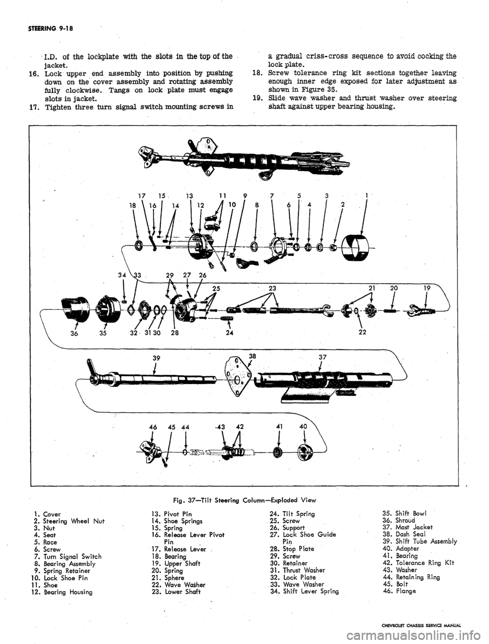
Fig.
37—Tilt Steering Column—Exploded View
1.
Cover
2.
Steering Wheel Nut
3. Nut
4.
Seat
5.
Race
6. Screw
7. Turn Signal Switch
8. Bearing Assembly
9. Spring Retainer
10.
Lock Shoe Pin
11.
Shoe
12.
Bearing Housing
13.
Pivot Pin
14.
Shoe Springs
15.
Spring
16.
Release Lever Pivot
Pin
17.
Release Lever
18.
Bearing
19.
Upper Shaft
20.
Spring
21.
Sphere
22.
Wave Washer
23.
Lower Shaft
24.
Tilt Spring
25.
Screw
26.
Support
27.
Lock Shoe Guide
Pin
28.
Stop Plate
29.
Screw
30.
Retainer
31.
Thrust Washer
32.
Lock Plate
33.
Wave Washer
34.
Shift Lever Spring
35.
Shift Bowl
36.
Shroud
37.
Mast Jacket
38.
Dash Seal
39.
Shift Tube Assembly
40.
Adapter
41.
Bearing
42.
Tolerance Ring Kit
43.
Washer
44.
Retaining Ring
45.
Bolt
46.
Flange
CHEVROLET CHASSIS SERVICE MANUAL
Page 463 of 659
STEERING 9-23
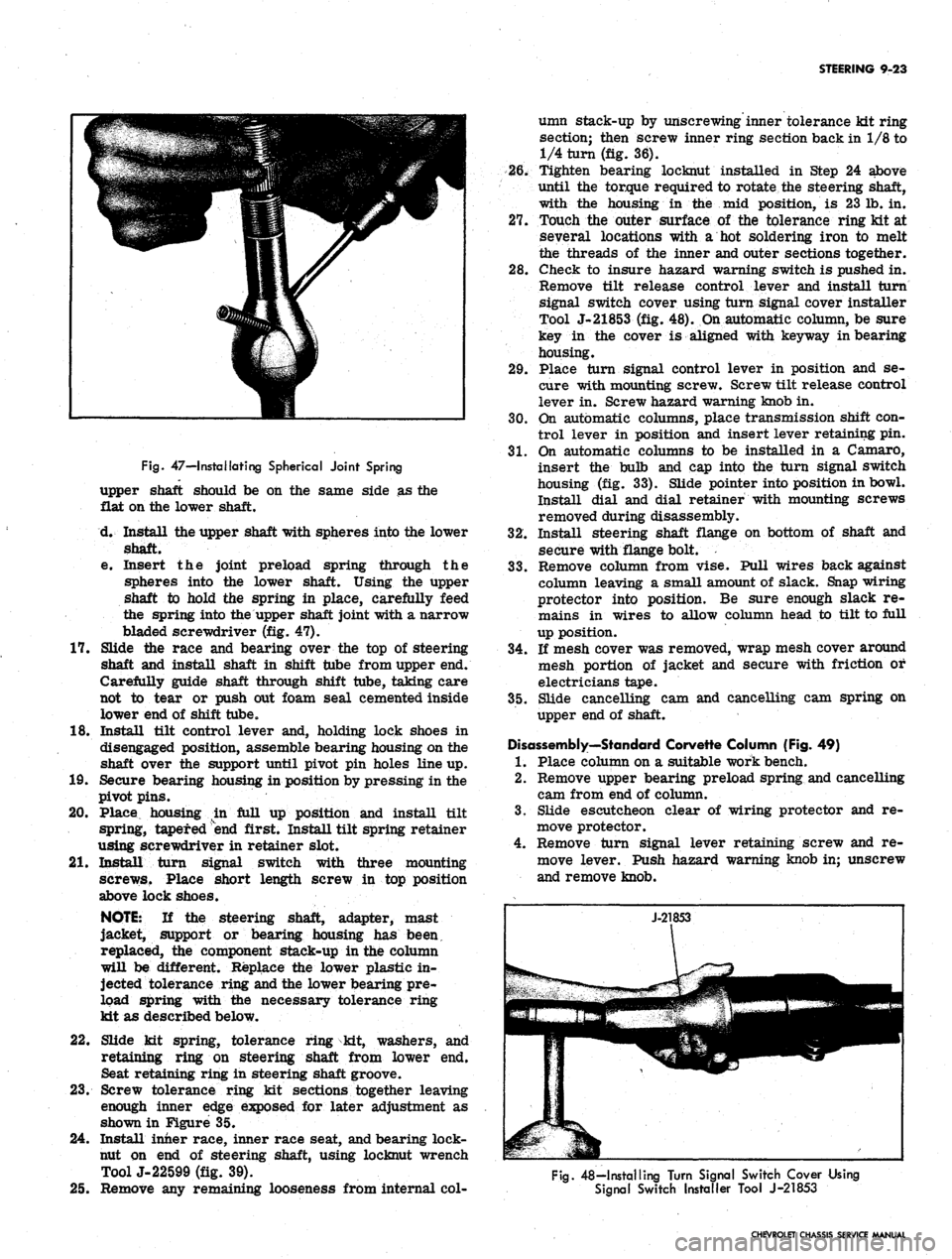
Fig.
47—I retaliating Spherical Joint Spring
upper shaft should be on the same side as the
flat on the lower shaft.
d. Install the upper shaft with spheres into the lower
shaft.
e. Insert the joint preload spring through the
spheres into the lower shaft. Using the upper
shaft to hold the spring in place, carefully feed
the spring into the upper shaft joint with a narrow
bladed screwdriver (fig. 47).
17.
Slide the race and bearing over the top of steering
shaft and install shaft in shift tube from upper end.
Carefully guide shaft through shift tube, taking care
not to tear or push out foam seal cemented inside
lower end of shift tube.
18.
Install tilt control lever and, holding lock shoes in
disengaged position, assemble bearing housing on the
shaft over the support until pivot pin holes line up.
19.
Secure bearing housing in position by pressing in the
pivot pins.
20.
Place housing in full up position and install tilt
spring, tapered end first. Install tilt spring retainer
using screwdriver in retainer slot.
21.
Install turn signal switch with three mounting
screws. Place short length screw in top position
above lock shoes.
NOTE:
If the steering shaft, adapter, mast
jacket, support or bearing housing has been,
replaced, the component stack-up in the column
will be different. Replace the lower plastic in-
jected tolerance ring and the lower bearing pre-
load spring with the necessary tolerance ring
kit as described below.
22.
Slide kit spring, tolerance ring kit, washers, and
retaining ring on steering shaft from lower end.
Seat retaining ring in steering shaft groove.
23.
Screw tolerance ring kit sections together leaving
enough inner edge exposed for later adjustment as
shown in Figure 35.
24.
Install inner race, inner race seat, and bearing lock-
nut on end of steering shaft, using locknut wrench
ToolJ-22599 (fig. 39).
25.
Remove any remaining looseness from internal col-
umn stack-up by unscrewing inner tolerance kit ring
section; then screw inner ring section back in 1/8 to
1/4 turn (fig. 36).
26.
Tighten bearing locknut installed in Step 24 above
until the torque required to rotate the steering shaft,
with the housing in the mid position, is 23 lb. in.
27.
Touch the outer surface of the tolerance ring kit at
several locations with a hot soldering iron to melt
the threads of the inner and outer sections together.
28.
Check to insure hazard warning switch is pushed in.
Remove tilt release control lever and install turn
signal switch cover using turn signal cover installer
Tool J-21853 (fig. 48). On automatic column, be sure
key in the cover is aligned with keyway in bearing
housing.
29.
Place turn signal control lever in position and se-
cure with mounting screw. Screw tilt release control
lever in. Screw hazard warning knob in.
30.
On automatic columns, place transmission shift con-
trol lever in position and insert lever retaining pin.
31.
On automatic columns to be installed in a Camaro,
insert the bulb and cap into the turn signal switch
housing (fig. 33). Slide pointer into position in bowl.
Install dial and dial retainer with mounting screws
removed during disassembly.
32.
Install steering shaft flange on bottom of shaft and
secure with flange bolt.
33.
Remove column from vise. Pull wires back against
column leaving a small amount of slack. Snap wiring
protector into position. Be sure enough slack re-
mains in wires to allow column head to tilt to full
up position.
34.
If mesh cover was removed, wrap mesh cover around
mesh portion of jacket and secure with friction or
electricians tape.
35.
Slide cancelling cam and cancelling cam spring on
upper end of shaft.
Disassembly—Standard Corvette Column (Fig. 49)
1.
Place column on a suitable work bench.
2.
Remove upper bearing preload spring and cancelling
cam from end of column.
3.
Slide escutcheon clear of wiring protector and re-
move protector.
4.
Remove turn signal lever retaining screw and re-
move lever. Push hazard warning knob in; unscrew
and remove knob.
Fig.
48—Installing Turn Signal Switch Cover Using
Signal Switch Installer Tool J-21853
CHEVROLET CHASSIS SERVICE MANUAL
Page 465 of 659
STEERING 9-25
\
£$&+
SIGNAL SWITCH
^ ^-BEARING
UPPER FLANGE^
HOUSING
COVER
»,
ESCUTCHEON
"^^^^^fr
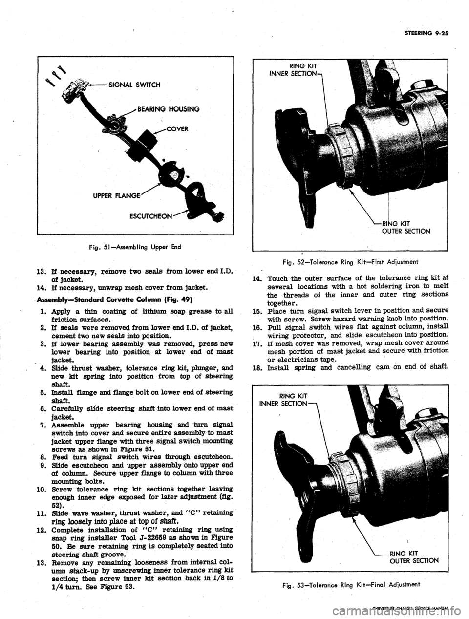
Fig.
51-Assembling Upper End
13.
If necessary, remove two seals from lower end I.D.
of jacket.
14.
If necessary, unwrap mesh cover from jacket.
Assembly—Standard Corvette Column (Fig. 49)
RING KIT V
INNER SEaiON-n 1
\
[1
3
^^•-
'^p|§
W- - V: -: ';'^ /
W ^-RI^G KIT
OUTER SECTION
Fig.
52—Tolerance Ring Kit—First Adjustment
14.
Touch the outer surface of the tolerance ring kit at
several locations with a hot soldering iron to melt
the threads of the inner and outer ring sections
together.
1.
4.
5.
6.
of lithium soap grease to all 15. Place turn signal switch lever in position and secure
10.
11.
12.
13.
Apply a thin coating
friction surfaces.
If seals were removed from lower end I.D. of jacket,
cement two new seals into position.
If lower bearing assembly was removed, press new
lower bearing into position at lower end of mast
jacket.
Slide thrust washer, tolerance ring kit, plunger, and
new kit spring into position from top of steering
shaft.
Install flange and flange bolt on lower end of steering
shaft.
Carefully slide steering shaft into lower end of mast
jacket.
Assemble upper bearing housing and turn signal
switch into cover and secure entire assembly to mast
jacket upper flange with three signal switch mounting
screws as shown in Figure 51.
Feed turn signal switch wires through escutcheon.
Slide escutcheon and upper assembly onto upper end
of column. Secure upper flange to column with three
mounting bolts.
Screw tolerance ring kit sections together leaving
enough inner edge exposed for later adjustment (fig.
52).
Slide wave washer, thrust washer, and "C" retaining
ring loosely into place at top of shaft.
Complete installation of "C" retaining ring using
snap ring installer Tool J-22659 as shown in Figure
50.
Be sure retaining ring is completely seated into
steering shaft groove.
Remove any remaining looseness from internal col-
umn stack-up by unscrewing inner tolerance ring kit
section; then screw inner kit section back in 1/8 to
1/4 turn. See Figure 53.
with screw. Screw hazard warning knob into position.
16.
Pull signal switch wires flat against column, install
wiring protector, and slide escutcheon into position.
17.
If mesh cover was removed, wrap mesh cover around
mesh portion of mast jacket and secure with friction
or electricians tape.
18.
Install spring and cancelling cam on end of shaft.
RING KIT
OUTER SECTION
fig.
53-Tolerance Ring Kit-Final Adjustment
CHEVROLET CHASSIS SERVICE MANUAL
Page 471 of 659

STEERING 9-31
Fig.
63—Freeing Ball Stud
rod threads with EP Chassis lube and install ends on
tie rod making sure both ends are threaded ah equal
distance from the tie rod.
2.
Make sure that threads on ball stud and in ball stud
nuts are perfectly clean and smooth. Install neoprene
seals on ball studs.
NOTE: If threads are not clean and smooth,
ball studs may turn in tie rod ends when at-
tempting to tighten nut.
3.
Install ball studs in steering arms and relay rod.
4.
Install ball stud nut, and install cotter pins. Lubri-
cate tie rod ends.
5.
Adjust toe-in as described in Section 3.
NOTE: Before locking clamp bolts on the rods,
make sure that the tie rod ends are in alignment
with their ball studs (each ball joint is in the
center of its travel). If the tie rod is not in
alignment with the studs, binding will result.
RELAY ROD-ALL MODELS EXCEPT CORVETTE
Removal
1.
Remove inner ends of tie rods from relay rod as
described under Tie Rod - Removal.
2.
Remove cotter pin and nut from relay rod ball stud
attachment at pitman arm.
3.
Detach relay rod from pitman arm. Shift steering
linkage as required to free pitman arm from relay
rod.
4.
Remove cotter pin and nut from idler arm and re-
move relay rod from idler arm.
Installation
1.
Install relay rod to idler arm, making certain idler
stud seal is in place, then install and tighten nut.
Advance nut just enough to align castellation with
cotter pin hole and install pin.
2.
Raise end of rod and install on pitman arm. Secure
with nut and cotter pin.
3.
Install tie rod ends to relay rod as previously
described under Tie Rods. Lubricate tie rod ends.
4.
Adjust toe-in (see Section 3) and align steering wheel
as described previously in this section under Steer-
ing Wheel Alignment and High Point Centering.
RELAY ROD-CORVETTE
Removal
1.
Remove steering damper from relay rod as outlined
under Steering Damper-Removal. Remove anchor
bracket from relay rod by disconnecting two mount-
ing bolts.
2.
Remove inner ends of tie rods from relay rod as
described under Tie Rod--Removal.
3.
Remove cotter pin from end of relay rod at pitman
arm ball stud attachment, and remove stud nut.
4.
Tap brJl stud out of pitman arm and lower relay rod.
5.
Remove cotter key and nut from idler arm and re-
move relay rod from idler arm. Remove washer and
seal from idler arm.
Installation
1.
Place relay rod on idler arm stud, making certain
idler stud seal and washer are in place, then install
and tighten nut. Advance nut just enough to align
castellation with cotter pin hole and install pin.
2.
Install new seal and clamp over ball at end of pitman
arm.
3.
Install inner spring seat and spring to relay rod.
4.
Raise end of rod and install on pitman arm.
5.
Install spring seat, spring, and end plug.
6. Tighten end plug until springs are compressed and
plug bottoms, then back off 3/4 turn plug amount
necessary to insert cotter pin. Insert cotter pin to
lock adjustment.
7.
Install tie rod ends to relay rod as previously de-
scribed under Tie Rods.
8. Lubricate tie rod ends and pitman arm to relay rod
ball joint.
9. Install steering damper bracket and tighten bolts.
Install damper as outlined under Steering Damper--
Installation.
10.
Adjust toe-in and align steering wheel as described
previously in this section.
IDLER ARM
Chevrolet, Chevelle, Comoro, and Corvette (Fig. 62)
Removal
1.
Remove idler arm to frame nut, washer, and bolt.
No washer is used on Corvette.
2.
Remove cotter pin and nut from idler arm to relay
rod ball stud.
3.
Remove relay rod from idler arm by tapping relay
rod with a hammer using a heavy hammer as a
backing.
4.
Remove idler arm.
Installation
1.
On Chevrolet, place seal in position on idler arm
stud; position stud up through frame, and secure with
lock washer and nut.
2.
On Chevelle, Camaro, and Corvette, position idler
CHEVROLET CHASSIS SERVICE MANUAL
Page 477 of 659
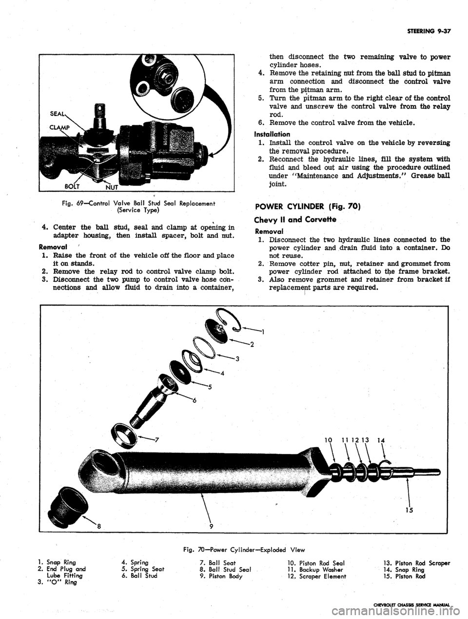
STEERING 9-37
NUT
Fig.
69—Control Valve Ball Stud Seal Replacement
(Service Type)
4.
Center the ball stud, seal and clamp at opening in
adapter housing, then install spacer, bolt and nut.
Removal
1.
Raise the front of the vehicle off the floor and place
it on stands.
2.
Remove the relay rod to control valve clamp bolt.
3.
Disconnect the two pump to control valve hose cdn-
nections and allow fluid to drain into a container,
then disconnect the two remaining valve to power
cylinder hoses.
4.
Remove the retaining nut from the ball stud to pitman
arm connection and disconnect the control valve
from the pitman arm.
5. Turn the pitman arm to the right clear of the control
valve and unscrew the control valve from the relay
rod.
6. Remove the control valve from the vehicle.
Installation
1.
Install the control valve on the vehicle by reversing
the removal procedure.
2.
Reconnect the hydraulic lines, fill the system with
fluid and bleed out air using the procedure outlined
under "Maintenance and Adjustments/' Grease ball
joint.
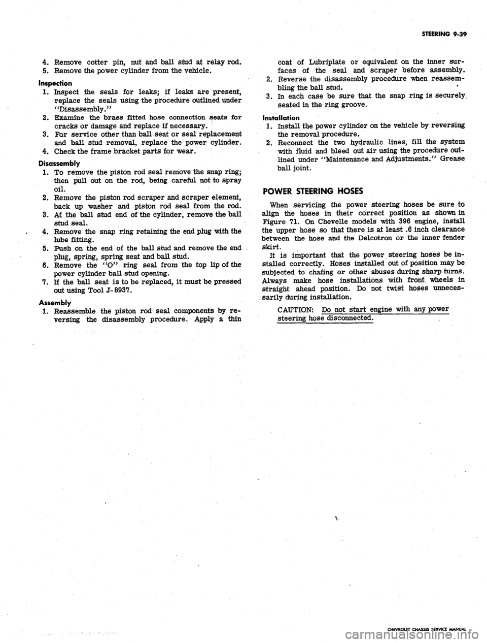
POWER CYLINDER (Fig. 70)
Chevy II and Corvette
Removal
1.
Disconnect the two hydraulic lines connected to the
power cylinder and drain fluid into a container. Do
not reuse.
2.
Remove cotter pin, nut, retainer and grommet from
power cylinder rod attached to the frame bracket.
3.
Also remove grommet and retainer from bracket if
replacement parts are required.
1.
Snap Ring
2.
End Plug and
Lube Fitting
3.
"O" Ring
Fig.
70—Power Cylinder—Exploded View
4.
Spring
5. Spring Seat
6. Ball Stud
7. Ball Seat
8. Ball Stud Seal
9. Piston Body
10.
Piston Rod Seal
11.
Backup Washer
•12.
Scraper Element
13.
Piston Rod Scraper
14.
Snap Ring
15.
Piston Rod
CHEVROLET CHASSIS SERVICE MANUAL
Page 479 of 659
STEERING 9-39
4.
Remove cotter pin, nut and ball stud at relay rod.
5. Remove the power cylinder from the vehicle.
Inspection
1.
Inspect the seals for leaks; if leaks are present,
replace the seals using the procedure outlined under
"Disassembly."
2.
Examine the brass fitted hose connection seats for
cracks or damage and replace if necessary.
3.
For service other than ball seat or seal replacement
and ball stud removal, replace the power cylinder.
4.
Check the frame bracket parts for wear.
Disassembly
1.
To remove the piston rod seal remove the snap ring;
then pull out on the rod, being careful not to spray
oil.
2.
Remove the piston rod scraper and scraper element,
back up washer and piston rod seal from the rod.
3.
At the ball stud end of the cylinder, remove the ball
stud seal.
4.
Remove the snap ring retaining the end plug with the
lube fitting.
5. Push on the end of the ball stud and remove the end
plug, spring, spring seat and ball stud.
6. Remove the "O" ring seal from the top lip of the
power cylinder ball stud opening.
7. If the ball seat is to be replaced, it must be pressed
out using Tool J-8937.
Assembly
1.
Reassemble the piston rod seal components by re-
versing the disassembly procedure. Apply a thin
coat of Lubriplate or equivalent on the inner sur-
faces of the seal and scraper before assembly.
2.
Reverse the disassembly procedure when reassem-
bling the ball stud.
3.
In each case be sure that the snap ring is securely,
seated in the ring groove.
Installation
1.
Install the power cylinder on the vehicle by reversing
the removal procedure.
2.
Reconnect the two hydraulic lines, fill the system
with fluid and bleed out air using the procedure out-
lined under "Maintenance and Adjustments." Grease
ball joint.
POWER STEERING HOSES
When servicing the power steering hoses be sure to
align the hoses in their correct position as shown in
Figure 71. On Chevelle models with 396 engine, install
the upper hose so that there is at least .6 inch clearance
between the hose and the Delcotron or the inner fender
skirt.
It is important that the power steering hoses be in-
stalled correctly. Hoses installed out of position may be
subjected to chafing or other abuses during sharp turns.
Always make hose installations with front wheels in
straight ahead position. Do not twist hoses unneces-
sarily during installation.
CAUTION: Do not start engine with any power
steering hose disconnected.
CHEVROLET CHASSIS SERVICE MANUAL
Page 485 of 659
WHEELS AND TIRES 10-5
WHEELS
The wheel and tire assembly should be removed from
vehicles equipped with disc brakes to properly perform
balancing operations. This is necessary due to drag of
the spring loaded brake shoes on the disc.
Static Balancing (W/Tire)
Static Balance (still balance) is the equal distribution
of weight of the wheel and tire assembly about the axis
of rotation so that the assembly has no tendency to rotate
by
itself.
Static unbalance causes the pounding action of
the front wheels that is called "tramp".
To correct static unbalance (front and rear): The
quickest and best methods to correct static unbalance
are through the use of wheel balancers which are com-
mercially available. Refer to the Information and in-
structions included with these balaricers.
Dynamic Balancing (W/Tire)
Dynamic Balance (running balance) requires the wheel
to be not only in static balance, but balanced and running
smoothly while turning on an axis which runs through the
centerline of the wheel and tire perpendicular to the axis
of rotation.
The quickest and best methods of testing and correcting
dynamic unbalance are by the use of dynamic wheel
balancers which are commercially available. These bal-
ancers include all necessary information on where and
how the balancing weights should be placed. The follow-
ing information, however, will help in the correction of
dynamic balance.
NOTE:
Before attempting to balance the
wheels, check to be certain that no foreign
matter has been trapped in the wheel ventila-
tion slots or in the accessory wheel discs. This
is especially important if the vehicle has been
run in soft mud and then parked in freezing
weather.
When a wheel that is statically unbalanced is dynam-
ically in balance the dynamic balance can be retained
while correcting "the static balance by installing the cor-
rective weights so that half of the weight required is
placed on the inner edge of the rim and the other half
on the outer edge of the rim.
Dynamic unbalance can be corrected without destroying
static balance by installing weights so half of weight
required for dynamic balance is placed on the rim op-
posite the heavy point, while the other half is placed 180°
away and on the opposite side of the rim.
NOTE:
Vehicles with wire wheel covers should
have the wheels balanced with the wire wheel
covers installed on the wheels.
Run Out (W/OTire)
The wheels should not run out (wobble) more than
1/16" as measured on the side of the rim at the base
of the tire. Excessive run-out is the result of a bent
wheel, an improperly mounted wheel, worn knuckle bear-
ings or steering connections. These parts should be
checked for correct adjustment, proper alignment and
wear whenever excessive run-out is encountered.
The wheels should also run concentric with the steering
knuckle spindle within 1/16 inch as measured on the tire
bead seat of the rim with the tire removed.
Wheel run-out, eccentricity and balance are closely
associated with steering and front wheel alignment.
Further information on these subjects will be found under
"Suspension".
Cleaning Aluminum Wheels
Do not use wire brush or abrasive cleaners when
cleaning wheels. Use only cleaners that will not react
with aluminum.
SERVICE OPERATIONS
TIRES
Removal
Dismounting tubeless tires presents no problems if the
correct procedures are used and the following precau-
tions observed.
1.
Remove the valve cap and valve core. Let out all the
air.
2.
Press the inner side of the tire into the rim well.
Use bead loosening tool or if regular tire irons are
used, take particular care not to injure or tear the
sealing ribs on the bead.
CAUTION: Never use tire irons with sharp
edges or corners.
3.
Using tire irons on the opposite side, remove bead,
taking small "bites" around the rim.
4.
Turn the tire over, and use two tire irons, one be-
tween the rim flange and the bead to pry the rim
upward, the other iron to pry outward between the
bead seat and the bead.
Installation
Extreme care must be exercised to prevent injury to
the sealing bead and circumferential bead when forcing
tire over rim.
1.
Apply a light film of Ruglyde or other suitable rubber
lubricant to sealing bead of tire.
NOTE:
The use of excessive lubrication may
lead to rim slippage and subsequent breaking of
air seal.
2.
Carefully mount the outer bead in usual manner by
using tire irons, taking small "bites" around rim,
being careful not to injure the tire bead.
CAUTION: DO NOT use a hammer, as damage
to the bead will result.
3.
Install the inner bead in the same manner.
NOTE:
If a seal cannot be effected in the fore-
going manner with the rush of air it can be
, accomplished by applying to the circumference
of the tire a tire mounting band or heavy sash
cord and tightening with the use of a tire iron.
On tire mounting machines, bouncing the tire
assembly is not required. The tire should be
CHEVROLET CHASSIS SERVICE MANUAL
Page 513 of 659
SECTION 12
ELECTRICAL-BODY AND CHASSIS
CONTENTS
OF
THIS
SECTION
Page
Page
System 12-1
Instruments and Gauges 12-21
Directional Signal 12r40
Windshield Wipers and Washers 12-44
Wiring Diagrams 12-56
Special Tools 12-60
LIGHTING SYSTEM
INDEX
Page
General Description
!2-i
Maintenance and Adjustments
•.................. 12-2
Headlamp Adjustment......................
12-3
Headlamp Panel Travel Adjustment.
12-5
Service Operations.
. . .. 12-5
Front Lighting
12-5
Headlamp
. 12_5
Parking Lamp
12-5
Fender Lamp
. 12_^
Headlamp Panel
12-8
Headlamp Panel Motor
^2-9
Rear Lighting
l2-10
Tail, Stop and Directional Lamps
12-10
Page
Backing Lamps
12-14
License Plate Lamp
12-14
Automatic Transmission Quadrant Lamp
12-14
Seat Separator Console Lamps
. 12-15
Lighting Switch
. . 12-15
Wiper Switch.
12-15
Stoplight Switch
12-15
Dimmer Switch
12-15
Backing Lamp Switches
12-15
Neutral Safety Switches
12-17
Parking Brake Alarm Switch
................. 12-19
Instrument Panel Compartment Lamp/Switch
12-19
Cirgarette Lighter
12-19
GENERAL DESCRIPTION
.
The lighting system includes: the main lighting switch,
stop light, dimmer, and backing lamp switches, head-
lamps, parking lamps, stop, tail and directional lamps,
instrument illumination and indicator lamps, and the
necessary wiring to complete the various circuits. A
fuse panel provides convenient power take offs and fuse
clips for the appropriate circuits (fig. 1).
Chevrolet and Chevelle headlamp installation is all
new in that the headlamps are located in the radiator
support with adjusting screws and springs. Eliminating
the need for having separate headlamp housings. Chev-
rolet and Chevelle headlamp retainers and springs are
interchangeable.
Chevy n headlamp housings are new because of revised
front end styling and Corvette front end lighting is basi-
cally carryover.
Front fender lamps have been added as an option for
Chevrolet models and as standard equipment on Caprice
series.
Camaro models use single headlamps and the Rally
Sport model headlamps are covered by a retractable
section of the grille when lamps are not used. The sec-
tion of the grille covering the headlamps folds back when
lights are required; the headlamps are stationary. The
covering is retracted by a small electric motor mounted
to the headlamp housing. The headlamps are automat-
ically uncovered when the headlight switch is pulled "ON"
for illumination. If at any time the electrical circuit
becomes inoperative, the lamps can be uncovered manu-
ally. The ignition switch must be
"ON"
in order to close
the headlamp doors.
Parking lamp for Chevelle and Chevrolet models are
new due to revised front end sheet metal and bumper
styling. Parking lamps are located in the bumper on
Chevrolet, Chevelle and Chevy n models
Camaro parking lamps are located in the radiator
grille except for the Rally Sport models on which the
parking lamps are in the valance panel. For styling
reasons, the lens is white and an amber glass bulb is
used. All Camaro parking lamps require a separate
ground wire to assure a good ground contact because of
the plastic grille and painted contact surfaces.
The Chevrolet tail, stop, and directional lamps are in
one housing with a three section lens design on Impala
and Caprice sedans. The center lens for Impala series
is the back-up lamp. The center lens on the Caprice is
a tail lamp with the back-up lamps being located in the
rear bumper. Chevrolet station wagons have three indi-
vidual housings with three lenses, the center lamp being
the back-up. Biscayne and Bel-Air sedans have a single
housing and lens for tail, stop, and directional lamp with
a similarly constructed back-up lamp inboard and adja-
cent to it.
Chevelle tail, stop, and directional lamps are a single
lens design that follows through with the rear fender
styling. The back-up lamp is located in r.ear bumper.
Camaro models except Rally Sport have tail lamps
with integral back-up lamps mounted inboard of the rear
fenders between the trunk opening and bumper. The
Rally Sport model has dual tail lamps in the rear housing
and valance mounted back-up lamps.
Corvette, Chevy n, and Corvair tail and directional
signal lights are carryover. The Corvette has new back-
up lamps center mounted above the license plate opening.
CHEVROLET CHASSIS SERVICE
Page 520 of 659
ELECTRICAL-BODY AND CHASSIS 12-8
is inserted through radiator support opening.
Remove two screws retaining lamp assembly to
lower sheet metal.
Remove three screws retaining lamp assembly to
lender.
To replace lamp assembly, reverse removal proce-
dure and check operation of the unit.
is aligned with flat on pivot shaft. Install stop lock
bolt and torque bolt to 45-60 in, lbs. Make sure that
side-to-side panel alignment is not changed when in-
stalling and tightening the stop.
CAUTION: Do not exceed specified torque
when tightening stop lock bolt.
HEADLAMP PANEL REPLACEMENT-CORVETTE
Refer to Figure 13 for Panel Mounting details.
1.
Remove engine compartment hood as outlined in
Section 1.
2.
Actuate headlamp panel to the open position.
NOTE:
In the event headlamp motor is inop-
erative, manual positioning of the panel can be
accomplished by turning the knurled knob at in-
board end of motor. As an assist in manual
operation of panel, apply light hand pressure to
panel in desired direction of rotation.
3.
Remove positive lead from battery terminal.
4.
Remove headlamp bezel retaining screws and bezel.
5. Remove the sealed beam housing unit as an assem-
bly - disconnect sealed beam leads at harness con-
nector and remove connector from sealed beam
leads;
remove the housing-to-panel retaining screws
and remove housing unit and wiring from panel.
6. Remove motor from panel pivot shaft - see motor
removal procedure. Then remove the panel stop
from panel inboard pivot shaft, and disconnect switch
lead wires from panel, support-mounted motor
switch.
7. Remove the panel retaining bolt access hole plugs
from inside the panel then rotate panel as required
and remove the retaining bolts and slide supports
from ends of panel pivot shaft. Remove bearing, felt
seal, retainer and washer from inboard pivot shaft.
8. Remove panel from its location by alternately disen-
gaging pivots from their retaining slots and with-
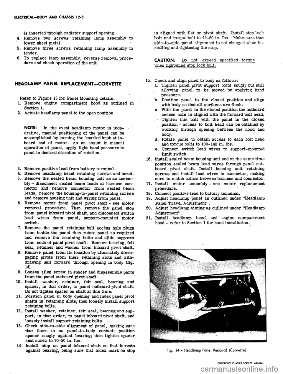
drawing unit forward through opening in body (fig.
14).
9. Loosen alien screw in spacer and disassemble parts
from the panel outboard pivot shaft.
10.
Install washer, retainer, felt seal, bearing and
spacer, in that order, to panel outboard pivot shaft.
Do not tighten spacer on shaft at this time.
11.
Position panel in body opening and index panel pivot
shafts in retaining slots; then loosely install support
retaining bolts.
12.
Install washer, retainer, felt seal, bearing and sup-
port, in that order, to panel inboard pivot shaft, and
loosely install support retaining bolts. -
13.
Check side-to-side alignment of panel, making sure
that there is no panel-to-body contact; position
spacer snugly against bearing; then tighten spacer
seat screw to 30-50 in. lbs.
14.
Install stop on panel inboard shaft so that it rests
against bearing, being sure that index mark on stop
15.
Check and align panel to body as follows:
a. Tighten panel pivot support bolts snugly but still
allowing panel to" be moved by applying hand
pressure.
b.
Position panel to the closed position and align
with body so that all surfaces are flush.
c. With the panel in the closed position the outboard
access hole is aligned with the forward bolt head.
Tighten this bolt with the panel in the closed
position - access to bolt head can be obtained by
working through opening between the hood and
body.
d. Rotate panel to obtain access to each bolt head
and torque bolts to 100-140 in. lbs.
e. Connect switch lead wires to support-mounted
limit switch.
16.
Install seaLed beam housing unit and at the same time
position sealed beam lead wires through panel out-
board pivot shaft. Install housing unit retaining
screws and install lead wires in connector, making
sure to match colors between harness and connector.
17.
Install motor assembly - see motor replacement
procedure.
18.
Connect positive lead to battery terminal.
19.
Adjust headlamp panel as outlined under "Headlamp
Panel Travel Adjustment".
20.
Adjust headlamp aiming as outlined under "Headlamp
Adjustment".
21.
Install headlamp bezel and engine compartment
hood - refer to Section 1 for hood installation.
Fig.
14
- Headlamp Panel Removal (Corvette)
CHEVROLET CHASSIS SERVICE MANUAL