set clock CHEVROLET CAMARO 1967 1.G Chassis User Guide
[x] Cancel search | Manufacturer: CHEVROLET, Model Year: 1967, Model line: CAMARO, Model: CHEVROLET CAMARO 1967 1.GPages: 659, PDF Size: 114.24 MB
Page 295 of 659
ENGINE 6-30
c". Install the valve locks and release the compres-
sor tool making sure the locks seat properly in
the upper groove of the valve stem.
NOTE: Grease may be used to hold the locks
in place while releasing the compressor tool.
396 and 427
cu.
in.
Engines
a. Install new valve stem oil seal (coated with oil)
in position over valve guide.
b.
Set the valve spring and damper and valve cap in
place.
c. Compress the spring with Tool J-5892 and install
the valve locks, then release the compressor tool,
making sure the locks seat properly in the groove
of the valve stem.
NOTE: Grease may be used to hold the locks
in place while releasing the compressor tool.
7.
Install spark ,plug, using a new gasket, and torque to
specifications. -
8. Install and adjust valve mechanism as outlined.
CYLINDER HEAD ASSEMBLY
Removal
1.
Remove intake manifold as outlined.
2.
Remove exhaust manifolds as outlined.
3.
Remove valve mechanism as outlined.
4.
Drain cooling system (block).
5.
Remove cylinder head bolts, cylinder head and gas-
ket. Place cylinder head on two blocks of wood to
prevent damage.
Installation
CAUTION: The gasket surfaces on both the
head and the block must be clean of any foreign
ttter and free of nicks or heavy scratches.
Under bolt threads in the block and threads on
Pie cylinder head bolt must be cleaned. (Dirt
will affect bolt torqueT)
1.
On engines using a STEEL gasket, coat both sides of
a new gasket with a good sealer, spread the sealer
thin and even. One method of applying the sealer that
will assure the proper- coat is with the use of a paint
roller. Too much sealer may hold the beads of the
gasket away from the head or block.
CAUTION: Use no sealer on engines using a
composition STEEL ASBESTOS gasket.
2.
Place the gasket in position over the dowel pins with
the bead up.
3.
Carefully guide cylinder head into place over dowel
pins and gasket.
4.
Coat threads of cylinder head bolts with sealing
compound and install finger tight.
5.
Tighten cylinder head bolts a little at a time in the
sequence shown on the torque sequence chart until
the specified torque is reached.
6. Install the exhaust manifold as outlined.
7.
Install the intake manifold as outlined.
8. Install and adjust the valve mechanism as outlined.
OIL
PAN
Removal
Chevrolet
and Camaro
1.
Disconnect battery positive cable.
2.
Disconnect distributor cap from distributor (to pr-e-
vent breaking distributor cap when engine is raised).
3.
Drain radiator, then disconnect lower radiator hose
at water pump and remove oil dip stick and tube
(where necessary). '
4.
Remove fan blade.
5.
Raise vehicle then drain engine oil;
6. Remove through bolts from engine front mounts.
Disconnect and remove starter.
7.
On vehicles equipped with automatic transmissions,
remove converter housing underpan.
8. Disconnect steering rod at idler lever then swing
steering linkage 4pwn for oil pan clearance.
9. Rotate crankshaft untii timing mark on torsional
damper is at 6:00 o'clock position.
10.
Using a suitable jack, and a block of wood to prevent
damaging oil pan, raise engine "enough to insert 2" x
4"
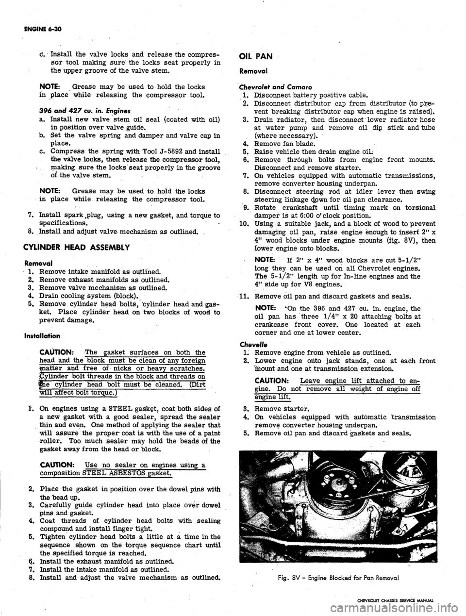
wood blocks under engine mounts (fig. 8V), then
lower engine onto blocks.
NOTE: If 2" x 4" wood blocks are cut 5-1/2"
long they can be used on all Chevrolet engines.
The 5-1/2" length up for In-line engines and the
4"
side up for V8 engines.
11.
Remove oil pan and discard gaskets and seals.
NOTE: -On the 396 and 427 cu. in. engine, the
oil pan has three 1/4" x 20 attaching bolts at ,
crankcase front cover. One located at each
corner and one at lower center.
Chevelle
1.
Remove engine from vehicle as outlined.
2.
Lower engine onto jack stands, one at each front
Tnaount and one at transmission extension.
CAUTION: Leave engine lift attached to en-
gine.
Do not remove all weight of engine off
engine lifET
3.
Remove starter.
4.
On vehicles equipped with automatic transmission
remove converter housing underpan.
5.
Remove oil pan and discard gaskets and seals.
Fig.
8V - Engine Blocked for Pan Removal
CHEVROLET CHASSIS SERVICE MANUAL
Page 296 of 659
ENGINE 6-31
Chevy II
1.
Disconnect battery positive cable.
2.
Drain engine oil.
3.
Disconnect and remove starter.
4 Disconnect steering idler arm bracket at right hand
frame rail and swing steering linkage down for pan
clearance.
5.
Disconnect* exhaust pipes at manifolds and allow
pipes to hang free.
6. Remove oil pan and discard gaskets and seals.
Corvette
1.
Disconnect battery positive cable then remove oil
dipstick and tube.
2.
Raise and support vehicle then drain engine oil.
3.
Remove starter and flywheel underpan.
4.
Disconnect steering linkage idler at frame and lower
the linkage.
5.
Remove oil pan and discard gaskets and seals.
6. On Hi-Performance engines, the oil baffle must
be removed before additional operations can be
performed.
NOTE: On the 427 cu. in. engine, the oil pan
has three 1/4" x 20 attaching bolts at crankcase
front cqver. One located at each corner and one
at lower center.
Installation
1.
Thoroughly clean all gasket sealing surfaces.
NOTE: Use a new pan. gasket set.
2.
Install side gaskets on pan rails, using.gasket sealer
as a retainer.
3.
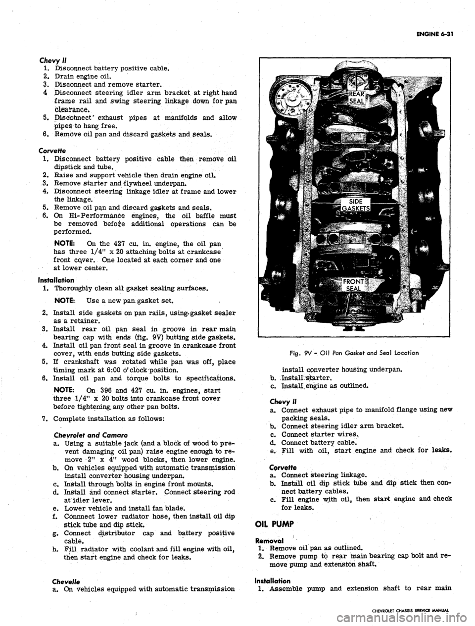
Install rear oil pan seal in groove in rear main
bearing cap with ends (fig. 9V) butting side gaskets.
4.
Install oil pan front seal in groove in .crankcaee front
cover, with ends butting side gaskets.
5.
If crankshaft was rotated while £>an was off, place
timing mark at 6:00 o'clock position.
6. Install oil pan and torque bolts to specifications.
NOTE: On 396 and 427 cu. in. engines, start
three 1/4" x 20 bolts into crankcase front cover
before tightening, any other pan bolts.
7.
Complete installation as follows:
Chevrolet
and Camaro
a. Using a suitable jack (and a block of wood to pre-
vent damaging oil pan) raise engine enough to re-
move 2" x 4" wood blocks, then lower engine.
b.
On vehicles equipped with automatic transmission
install converter housing underpan.
c. Install through bolts in engine front mounts.
d. Install and connect starter. Connect steering rod
at idler lever.
e. Lower vehicle and install fan blade.
f. Cbnnnect lower radiator hose, then install oil dip
stick tube and dip stick.
g. Connect distributor cap and battery positive
cable.
h. Fill radiator with coolant and fill engine with oil,
then start engine and check for leaks.
Chevelle
a. On vehicles equipped with automatic transmission
Fig.
9V - Oil Pan Gasket and Seal Location
install converter housing underpan.
b.
.Install starter.
c. Install, engine as outlined.
Chevy II
a. Connect exhaust pipe to manifold flange using new
packing seals.
b.
Connect steering idler arm bracket.
c. Connect starter wires..
d. Connect battery cable.
e. Fill with oil, start engine and check for leaks.
Corvette
a. Connect steering linkage.
b.
Install oil dip stick tube and dip stick then con-
nect battery cables.
c. Fill engine with oil, then start engine and check
for leaks.
OIL PUMP
Removal
1.
Remove oil pan as outlined.
2.
Remove pump to rear main bearing cap bolt and re-
move pump and extension shaft.
Installation
1.
Assemble pump and extension shaft to rear main
CHEVROLET CHASSIS SERVICE MANUAL
Page 312 of 659
ENGINE FUEL 6M-4
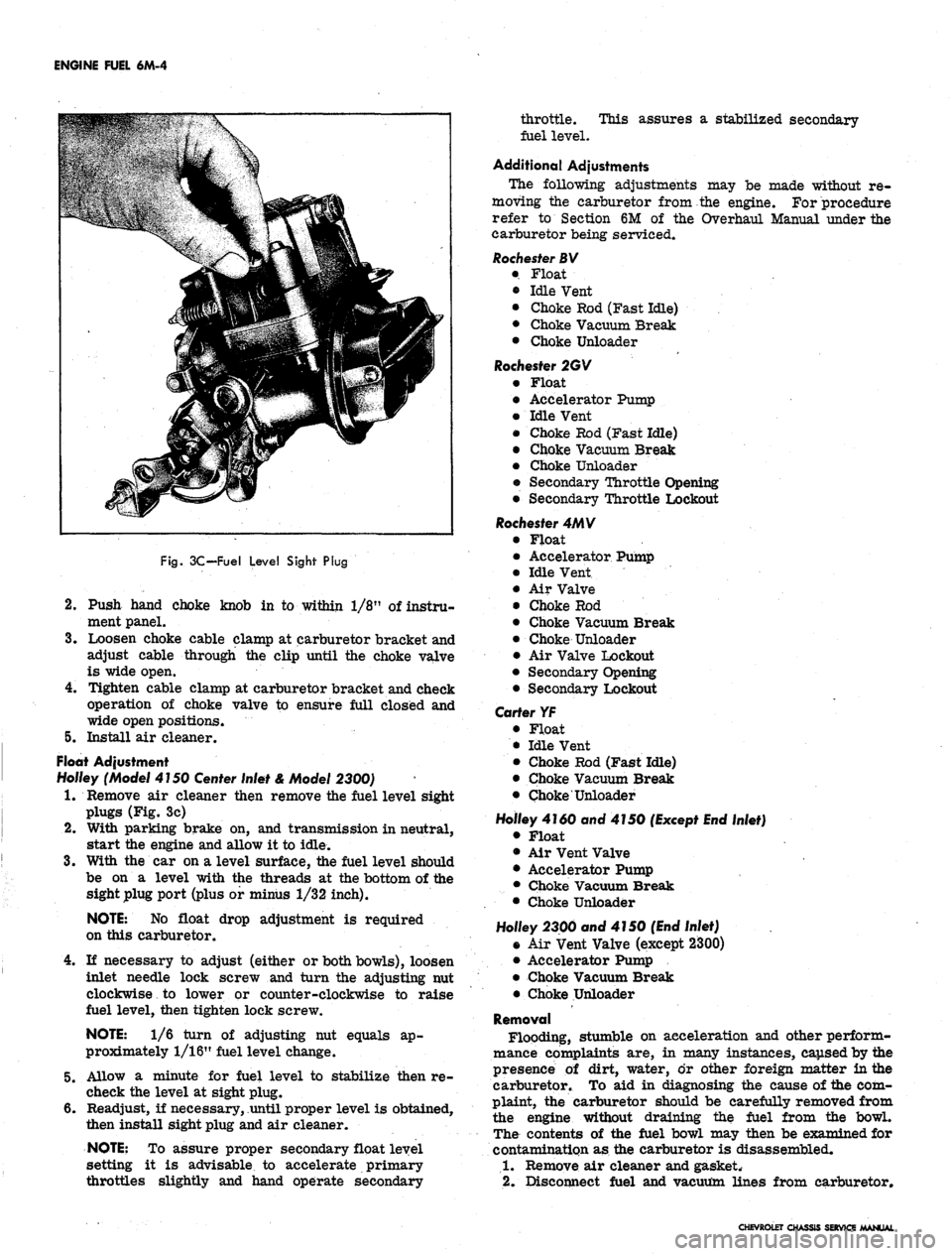
Fig.
3C-Fuel Level Sight Plug
2.
Push hand choke knob in to within 1/8" of instru-
ment panel.
3.
Loosen choke cable clamp at carburetor bracket and
adjust cable through the clip until the choke valve
is wide open.
4.
Tighten cable clamp at carburetor bracket and check
operation of choke valve to ensure full closed and
wide open positions.
5. Install air cleaner.
Float Adjustment
Ho/fey (Model 4150
Center
Inlet & Model 2300)
1.
Remove air cleaner then remove the fuel level sight
plugs (Fig. 3c)
2.
With parking brake on, and transmission in neutral,
start the engine and allow it to idle.
3.
With the car on a level surface, the fuel level should
be on a level with the threads at the bottom of the
sight plug port (plus or minus 1/32 inch).
NOTE:
No float drop adjustment is required
on this carburetor.
4.
If necessary to adjust (either or both bowls), loosen
inlet needle lock screw and turn the adjusting nut
clockwise to lower or counter-clockwise to raise
fuel level, then tighten lock screw.
NOTE:
1/6 turn of adjusting nut equals ap-
proximately 1/16" fuel level change.
5. Allow a minute for fuel level to stabilize then re-
check the level at sight plug.
6. Readjust, if necessary, until proper level is obtained,
then install sight plug and air cleaner.
NOTE:
To assure proper secondary float level
setting it is advisable to accelerate primary
throttles slightly and hand operate secondary
throttle. This assures a stabilized secondary
fuel level.
Additional Adjustments
The following adjustments may be made without re-
moving the carburetor from the engine. For procedure
refer to Section 6M of the Overhaul Manual under the
carburetor being serviced.
Rochester BV
• Float
• Idle Vent
• Choke Rod (Fast Idle)
• Choke Vacuum Break
• Choke Unloader
Rochester 2GV
• Float
• Accelerator Pump
• Idle Vent
• Choke Rod (Fast Idle)
• Choke Vacuum Break
• Choke Unloader
• Secondary Throttle Opening
• Secondary Throttle Lockout
Rochester 4MV
• Float
• Accelerator Pumj)
• Idle Vent
• Air Valve
• Choke Rod
• Choke Vacuum Break
• Choke Unloader
• Air Valve Lockout
• Secondary Opening
• Secondary Lockout
Carter YF
• Float
• Idle Vent
• Choke Rod (Fast Idle)
• Choke Vacuum Break
• Choke Unloader
Holley 4160 and 4150
(Except End
Inlet)
• Float
• Air Vent Valve
• Accelerator Pump
• Choke Vacuum Break
• Choke Unloader
Holley 2300 and 4150
(End
Inlet)
• Air Vent Valve (except 2300)
• Accelerator Pump
• Choke Vacuum Break
• Choke Unloader
Removal
Flooding, stumble on acceleration and other perform-
mance complaints are, in many instances, caused by the
presence of dirt, water, or other foreign matter in the
carburetor. To aid in diagnosing the cause of the com-
plaint, the carburetor should be carefully removed from
the engine without draining the fuel from the bowl.
The contents of the fuel bowl may then be examined for
contamination as the carburetor is disassembled.
1.
Remove air cleaner and gasket.
2.
Disconnect fuel and vacuum lines from carburetor.
CHEVROLET CHASSIS SERVICE MANUAL
Page 336 of 659
ENGINE-ELECTRICAL 6Y-11
I
BAT
JUNCTION BLOCK
DELCOTRON
—GRQ
BATTERY
&HJVVWV
0 VA OHM TEST RELAY >
RESISTOR [ 1 d
FUSIBLE
LINK
TO CRANKING
MOTOR
Ik
REGULATOR
VOLTMETER
FUSIBLE LINK
IGN.
SWITCH
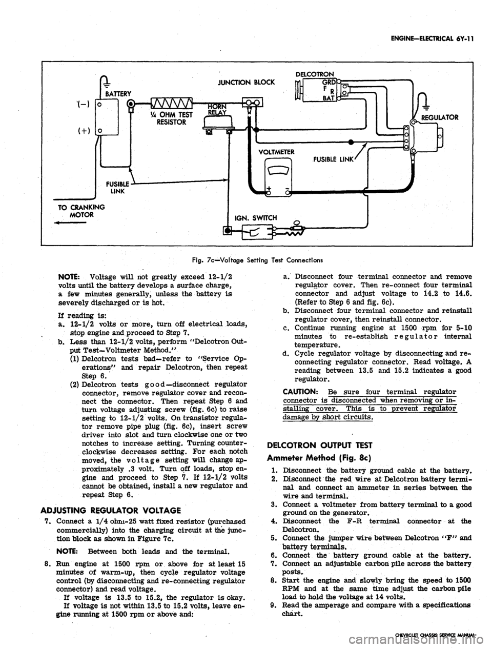
Fig.
7c—Voltage Setting Test Connections
NOTE:
Voltage will not greatly exceed 12-1/2
volts until the battery develops a surface charge,
a few minutes generally, unless the battery is
severely discharged or is hot.
If reading is:
a. 12-1/2 volts or more, turn off electrical loads,
stop engine and proceed to Step 7.
b.
Less than 12-1/2 volts, perform "Delcotron Out-
put Test-Voltmeter Method."
(1) Delcotron tests bad—refer to "Service Op-
erations" and repair Delcotron, then repeat
Step 6.
(2) Delcotron tests good—disconnect regulator
connector, remove regulator cover and recon-
nect the connector. Then repeat Step 6 and
turn voltage adjusting screw (fig. 6c) to raise
setting to 12-1/2 volts. On transistor regula-
tor remove pipe plug (fig. 6c), insert screw
driver into slot and turn clockwise one or two
notches to increase setting. Turning counter-
clockwise decreases setting. For each notch
moved, the voltage setting will change ap-
proximately .3 volt. Turn off loads, stop en-
gine and proceed to Step 7. If 12-1/2 volts
cannot be obtained, install a new regulator and
repeat Step 6.
ADJUSTING REGULATOR VOLTAGE
7. Connect a 1/4 ohm-25 watt fixed resistor (purchased
commercially) into the charging circuit at the junc-
tion block as shown in Figure 7c.
NOTE:
Between both leads and the terminal.
8. Run engine at 1500 rpm or above for at least 15
minutes of warm-up, then cycle regulator voltage
control (by disconnecting and re-connecting regulator
connector) and read voltage.
If voltage is 13.5 to 15.2, the regulator is okay.
If voltage is not within 13.5 to 15.2 volts, leave en-
gine running at 1500 rpm or above and:
a. Disconnect four terminal connector and remove
regulator cover. Then re-connect four terminal
connector and adjust voltage to i4.2 to 14.6.
(Refer to Step 6 and fig. 6c).
b.
Disconnect four terminal connector and reinstall
regulator cover, then reinstall connector.
c. Continue running engine at 1500 rpm for 5-10
minutes to re-establish regulator internal
temperature.
d. Cycle regulator voltage by disconnecting and re-
connecting regulator connector. Read voltage. A
reading between 13.5 and 15.2 indicates a good
regulator.
CAUTION: Be sure four terminal regulator
connector is disconnected when removing or in-
stalling cover. This is to prevent regulator
damage by short circuits.
DELCOTRON OUTPUT TEST
Ammeter Method (Fig. 8c)
1.
Disconnect the battery ground cable at the battery.
2.
Disconnect the red wire at Delcotron battery termi-
nal and connect an ammeter in series between the
wire and terminal.
3.
Connect a voltmeter from battery terminal to a good
ground on the generator.
4.
Disconnect the F-R terminal connector at the
Delcotron.
5. Connect the jumper wire between Delcotron "F" and
battery terminals.
6. Connect the battery ground cable at the battery.
7. Connect an adjustable carbon pile across the battery
posts.
8. Start the engine and slowly bring the speed to 1500
RPM and at the same time adjust the carbon pile
load to hold the voltage at 14 volts.
9. Read the amperage and compare with a specifications
chart.
CHEVROLET CHASSIS SERVICE MANUAL
Page 347 of 659
ENGINE-ELECTRICAL 6Y-22
ADJUST DWELL
ANGLE SETTING OR
POINT OPENING
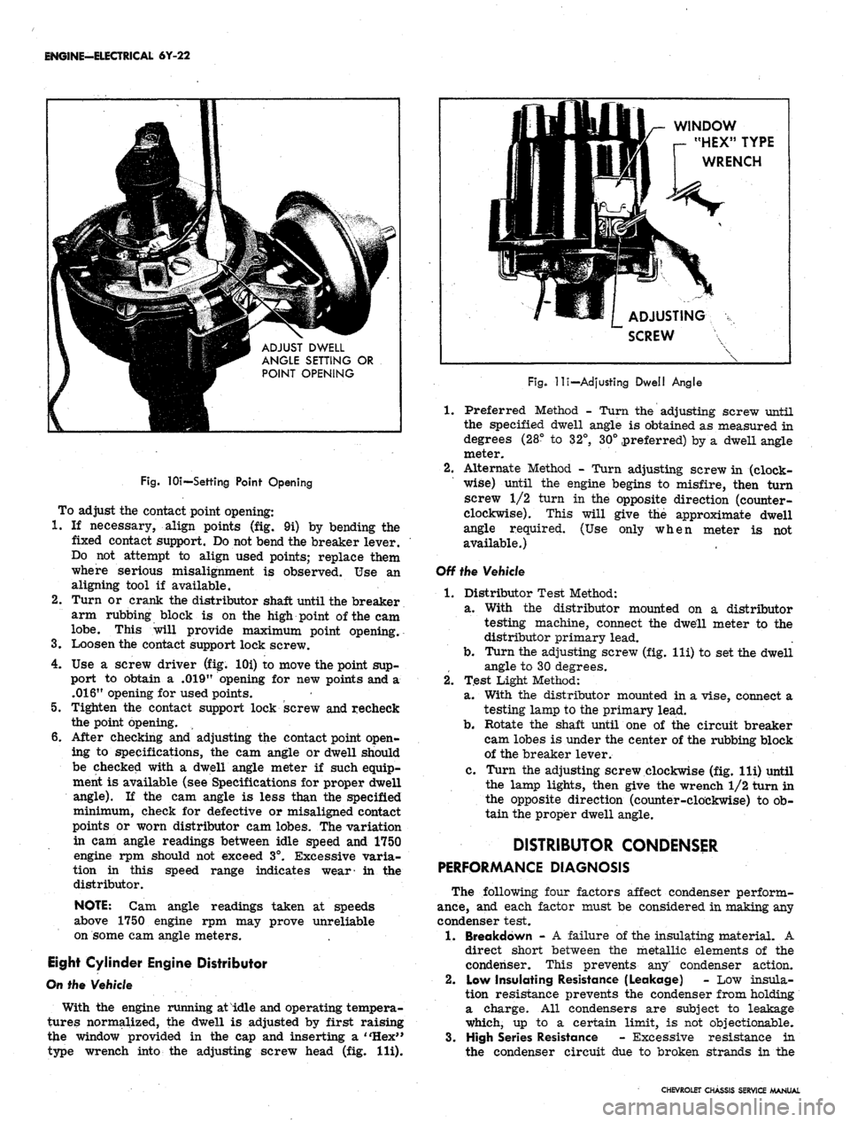
Fig.
lOi—Settihg Point Opening
To adjust the contact point opening:
1.
If necessary, align points (fig. 9i) by bending the
fixed contact support. Do not bend the breaker lever.
Do not attempt to align used points; replace them
where serious misalignment is observed. Use an
aligning tool if available.
2.
Turn or crank the distributor shaft until the breaker
arm rubbing block is on the high point of the cam
lobe.
This will provide maximum point opening.
3.
Loosen the contact support lock screw.
4.
Use a screw driver (fig. lOi) to move the point sup-
port to obtain a .019" opening for new points and a
.016"
opening for used points.
5.
Tighten the contact support lock screw and recheck
the point opening.
6. After checking and adjusting the contact point open-
ing to specifications, the cam angle or dwell should
be checked with a dwell angle meter if such equip-
ment is available (see Specifications for proper dwell
angle).
If the cam angle is less than the specified
minimum, check for defective or misaligned contact
points or worn distributor cam lobes. The variation
in cam angle readings between idle speed and 1750
engine rpm should not exceed 3°. Excessive varia-
tion in this speed range indicates wear- in the
distributor.
NOTE:
Cam angle readings taken at speeds
above 1750 engine rpm may prove unreliable
on some cam angle meters.
Eight Cylinder Engine Distributor
On the Vehicle
With the engine running at idle and operating tempera-
tures normalized, the dwell is adjusted by first raising
the window provided in the cap and inserting a "Hex"
type wrench into the adjusting screw head (fig. Hi).
WINDOW
r- "HEX" TYPE
WRENCH
ADJUSTING
SCREW
Fig.
-lli—Adjusting Dwell Angle
1.
Preferred Method - Turn the adjusting screw until
the specified dwell angle is obtained as measured in
degrees (28° to 32°, 30° preferred) by a dwell angle
meter.
2.
Alternate Method - Turn adjusting screw in (clock-
wise) until the engine begins to misfire, then turn
screw 1/2 turn in the opposite direction (counter-
clockwise). This will give the approximate dwell
angle required. (Use only when meter is not
available.)
Off the Vehicle
1.
Distributor Test Method:
a. With the distributor mounted on a distributor
testing machine, connect the dwell meter to the
distributor primary lead.
b.
Turn the adjusting screw (fig. lli) to set the dwell
angle to 30 degrees.
2.
Test Light Method:
a. With the distributor mounted in a vise, connect a
testing lamp to the primary lead.
b.
Rotate the shaft until one of the circuit breaker
cam lobes is under the center of the rubbing block
of the breaker lever.
c. Turn the adjusting screw clockwise (fig. lli) until
the lamp lights, then give the wrench 1/2 turn in
the opposite direction (counter-clockwise) to ob-
tain the proper dwell angle.
DISTRIBUTOR CONDENSER
PERFORMANCE DIAGNOSIS
The following four factors affect condenser perform-
ance,
and each factor must be considered in making any
condenser test.
1.
Breakdown - A failure of the insulating material. A
direct short between the metallic elements of the
condenser. This prevents any' condenser action.
2.
Low Insulating Resistance (Leakage) - Low insula-
tion resistance prevents the condenser from holding
a charge. All condensers are subject to leakage
which, up to a certain limit, is not objectionable.
3.
High Series Resistance - Excessive resistance in
the condenser circuit due to broken strands in the
CHEVROLET CHASSIS SERVICE MANUAL
Page 352 of 659
ENGINE-ELECTRICAL 6Y-27
timing mark on pulley lines up with timing tab.
2.
Position distributor to opening in block in normal
installed attitude (fig. 15i), noting position of vacuum
control unit.
3.
Position rotor to point toward front of engine (with
distributor housing held in installed attitude), then
turn rotor counter-clockwise approximately 1/8 turn
more toward left cylinder bank and push distributor
down to engine camshaft. It may be necessary to ro-
tate rotor slightly until camshaft engagement is felt.
4.
While pressing firmly down on distributor housing,
kick starter over a few times to make sure oil pump
shaft is engaged. Install hold-down clamp and bolt
and snug up bolt.
5. Turn distributor body slightly until points just open
and tighten distributor clamp bolt.
6. Place distributor cap in position and check to see
that rotor lines up with terminal for No. 1 spark
plug.
7. Install cap, check all high tension wire connections
and connect spark plug wires if they have been re-
moved. It is important that the wires be installed in
their location in the supports.
NOTE:
The brackets are numbered to show the
correct installation. Wires must be installed as
indicated to prevent cross firing.
8. Connect vacuum line to distributor and distributor
primary wire to coil terminal.
9. Start engine and set timing as described under Turn-
Up in Section 6.
BREAKERLESS (MAGNETIC PULSE)
DISTRIBUTOR
REMOVAL (CORVETTE)
1.
If vehicle is equipped with radio, remove three bolts
securing ignition shield over distributor and coil.
One bolt is accessible from the top of shield, the
other two are at rear of shield, facing firewall.
2.
Disconnect tachometer drive cables from distributor
housing.
3.
Disconnect pickup coil leads at connector.
4.
Remove distributor cap.
5. Crank engine so rotor is in position to fire No. 1
cylinder and timing mark on harmonic balancer is
indexed with pointer.
6. Remove vacuum line from distributor.
7. Remove distributor clamping screw and hold-down
clamp.
8. Remove distributor and distributor-to-block gasket.
It will be noted that the rotor will rotate as the
distributor is pulled out of the block. Mark the re-
lationship of the rotor and the distributor housing
after removal so that the rotor can be set in the
same position when the distributor is being installed.
DISASSEMBLY (Fig. 16i)
NOTE:
If a distributor is being disassembled
for replacement of the stationary magnetic
pickup assembly only, it will be necessary to
perform only Steps 3, 4, 5, 7, 8, 9, and 12 of the
service procedure listed below.
1.
Remove screws securing rotor and remove rotor.
2.
Remove centrifugal weight springs and weights.
3.
Remove the tachometer drive gear from the distribu-
tor (Corvette only).
4.
Remove roll pin, then remove distributor drive gear
and washer.
CAUTION: To prevent
magnet, support drive gear
;e to the permanent
?n
driving out roll
pin.
5. Remove drive shaft assembly.
6. Remove centrifugal weight support and timer core
from drive shaft.
7. Remove connector from pickup coil leads.
8. Remove retaining ring which secures magnetic
core support plate to distributor shaft bushing in
housing.
9. As a unit, remove the entire magnetic pickup assem-
bly from the distributor housing.
10.
Remove brass washer and felt pad.
11.
Remove vacuum advance unit.
12.
To reassemble distributor, perform the above steps
in reverse order.
INSTALLATION (CORVETTE)
1.
Check to see that the engine is at firing position for
No.
1 cylinder (timing mark on harmonic balancer
indexed with pointer).
2.
Position a new distributor-to-block gasket on the
block.
3.
Before installing distributor, index rotor with hous-
ing as noted when distributor was removed. Install
distributor in block so that vacuum diaphragm faces
approximately 45° forward on the right side of the
engine and the rotor points toward contact in cap for
No.
1 cylinder.
4.
Replace distributor clamp leaving screw loose
enough to allow distributor to be turned for timing
adjustment.
5. Install spark plug wires in distributor cap. Place
wire for No. 1 cylinder in tower (marked on old cap
during disassembly) then install remaining wires
clockwise around the cap according to the firing
order (1-8-4-3-6-5-7-2).
6. Attach distributor to coil primary wires.
7. Replace distributor cap.
8. Adjust timing and then fully tighten distributor clamp
screw.
9. Attach vacuum line to distributor.
10.
Connect tachometer drive cables to distributor body.
11.
Replace ignition shields.
DISTRIBUTOR OFF-ENGINE TEST
The distributor's centrifugal and vacuum advance can
be checked in a distributor testing machine or synchro-
scope specially adapted or designed to accommodate this
type distributor. However, since this involves removing
the distributor from the engine, this test may be post-
poned until other system checks have been made. A dwell
reading cannot be obtained on this distributor and it is not
likely that the centrifugal or vacuum advance will be a
cause of trouble.
COIL REPLACEMENT
1.
Disconnect ignition switch and distributor leads from
CHEVROLET CHASSIS SERVICE MANUAL
Page 384 of 659
CLUTCH AND TRANSMISSIONS 7-25
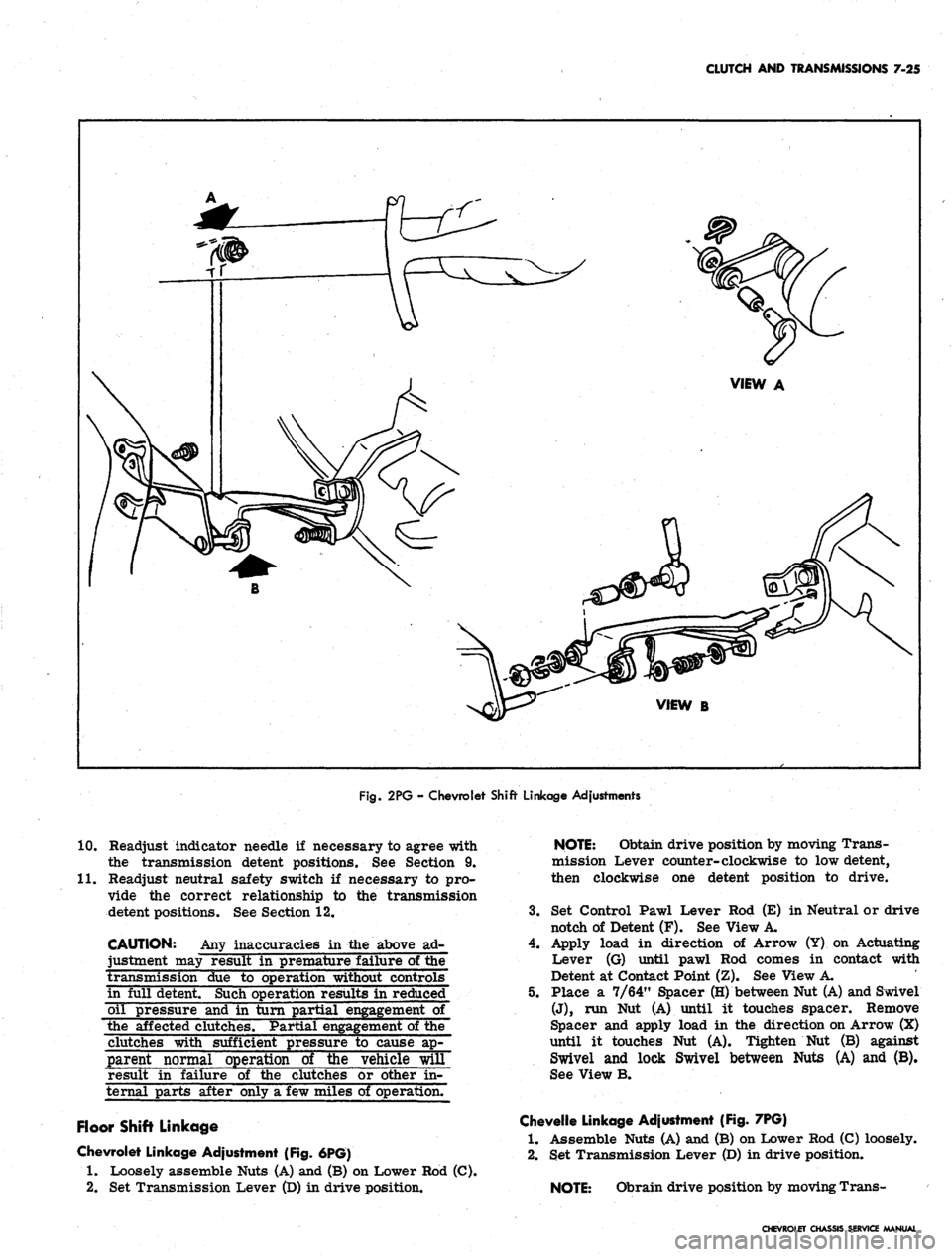
Fig.
2PG - Chevrolet Shift Linkage Adjustments
10.
11.
Readjust indicator needle if necessary to agree with
the transmission detent positions. See Section 9.
Readjust neutral safety switch if necessary to pro-
vide the correct relationship to the transmission
detent positions. See Section 12.
CAUTION: Any inaccuracies in the above ad-
justment may result in premature failure of the
transmission due to operation without controls
in full detent. Such operation results in reduced
oil pressure and in turn partial engagement of
the affected clutches. Partial
of the
clutches with sufficient pressure to cause ap-
parent normal operation of the vehicle will
result in failure of the clutches or other in-
ternal parts after only a few miles of operation.
Floor Shift Linkage
Chevrolet Linkage Adjustment (Fig. 6PG)
1.
Loosely assemble Nuts (A) and (B) on Lower Rod (C).
2.
Set Transmission Lever (D) in drive position.
NOTE:
Obtain drive position by moving Trans-
mission Lever counter-clockwise to low detent,
then clockwise one detent position to drive.
3.
Set Control Pawl Lever Rod (E) in Neutral or drive
notch of Detent (F). See View A.
4.
Apply load in direction of Arrow (Y) on Actuating
Lever (G) until pawl Rod comes in contact with
Detent at Contact Point (Z). See View A.
5. Place a 7/64" Spacer (H) between Nut (A) and Swivel
(J),
run Nut (A) until it touches spacer. Remove
Spacer and apply load in the direction on Arrow (X)
until it touches Nut (A). Tighten Nut (B) against
Swivel and lock Swivel between Nuts (A) and (B).
See View B.
Chevelle Linkage Adjustment (Fig. 7PG)
1.
Assemble Nuts (A) and (B) on Lower Rod (C) loosely.
2.
Set Transmission Lever (D) in drive position.
NOTE:
Obrain drive position by moving Trans-
CHEVROLET CHASSIS SERVICE MANUAL
Page 386 of 659
CLUTCH AND TRANSMISSIONS 7-27
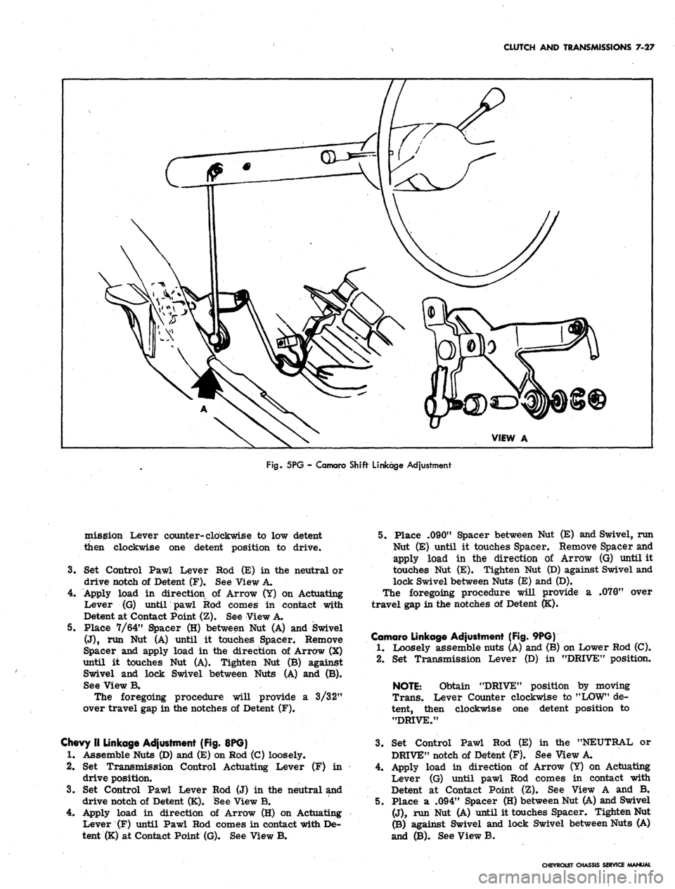
Fig.
5PG - Camaro Shift Linkage Adjustment
mission Lever counter-clockwise to low detent
then clockwise one detent position to drive.
3.
Set Control Pawl Lever
drive notch of Detent (F).
Rod (E) in the neutral or
See View A.
4.
Apply load in direction of Arrow (Y) on Actuating
Lever (G) until pawl Rod comes in contact with
Detent at Contact Point (Z). See View A.
5. Place 7/64" Spacer (H) between Nut (A) and Swivel
(J),
run Nut (A) until it touches Spacer. Remove
Spacer and apply load in the direction of Arrow (X)
until it touches Nut (A). Tighten Nut (B) against
Swivel and lock Swivel between Nuts (A) and (B).
See View B.
The foregoing procedure will provide a 3/32"
over travel gap in the notches of Detent (F).
Chevy II Linkage Adjustment (Fig. 8PG)
1.
Assemble Nuts (D) and (E) on Rod (C) loosely.
2.
Set Transmission Control Actuating Lever (F) in
drive position.
3.
Set Control Pawl Lever Rod (J) in the neutral and
drive notch of Detent (K). See View B.
4.
Apply load in direction of Arrow (H) on Actuating
Lever (F) until Pawl Rod comes in contact with De-
tent (K) at Contact Point (G). See View B.
5. Place .090" Spacer between Nut (E) and Swivel, run
Nut (E) until it touches Spacer. Remove Spacer and
apply load in the direction of Arrow (G) until it
touches Nut (E). Tighten Nut (D) against Swivel and
lock Swivel between Nuts (E) and (D).
The foregoing procedure will provide a .070" over
travel gap in the notches of Detent (K).
Camaro Linkage Adjustment (Fig. 9PG)
1.
Loosely assemble nuts (A) and (B) on Lower Rod (C).
2.
Set Transmission Lever (D) in "DRIVE" position.
NOTE:
Obtain "DRIVE" position by moving
Trans. Lever Counter clockwise to "LOW" de-
tent, then clockwise one detent position to
"DRIVE."
3.
Set Control Pawl Rod (E) in the "NEUTRAL or
DRIVE" notch of Detent (F). See View A.
4.
Apply load in direction of Arrow (Y) on Actuating
Lever (G) until pawl Rod comes in contact with
Detent at Contact Point (Z). See View A and B.
5. Place a .094" Spacer (H) between Nut (A) and Swivel
(J),
run Nut (A) until it touches Spacer. Tighten Nut
(B) against Swivel and lock Swivel between Nuts (A)
and (B). See View B.
CHEVROLET CHASSIS SERVICE MANUAL
Page 395 of 659
CLUTCH AND TRANSMISSIONS 7-36
TURBO HYDRA-MATIC TRANSMISSION
INDEX
Page
General Description . . , . 7-36
Maintenance and Adjustments . 7-37
Transmission Fluid 7-37
Fluid Level Indicator 7-37
Shift Control Linkage Adjustment ........... 7-37
Neutral Safety Switch Adjustment 7-37
Draining and Refilling Transmission . . . 7-37
Pressure Regulator Valve 7-38
Control Valve Body . 7-39
Governor ..'.... 7-40
Modulator and Modulator Valve 7-40
Parking Linkage . . 7-40
Page
Rear Seal -. 7-40
Other Service Operations . . 7-40
Transmission Replacement 7-40
Turbo Hydra-Matic Diagnosis Procedure. ......... 7-41
Sequence . ; ; 7-41
Oil Level and Condition Check 7-41
Manual Linkage 7-41
Oil Leaks .' 7-41
Case Porosity - Repair ................ 7-42
Oil Pressure Check 7-42
Transmission Shift Points 7-42
Special Tools 7-43
GENERAL DESCRIPTION
The Turbo Hydra-Matic transmission is a fully auto-
matic unit consisting primarily of a 3-element hydraulic
torque converter and a compound planetary gear set.
Three multiple-disc clutches, one sprag unit, one roller
clutch and two bands provide the friction elements re-
quired to obtain the desired function of the compound
planetary gear set.
The torque converter couples the engine to the plane-
tary gears through oil and provides hydraulic torque
multiplication when required. The compound planetary
gear set produces three forward speeds and reverse.
The
3-
element torque converter consists of a pump or
driving member, a turbine or driven member, and a
stator assembly. The stator is mounted on a one-way
roller clutch which will allow the stator to turn clock-
wise but not counter-clockwise.
The torque converter housing is filled with oil and
is attached to the engine crankshaft by a flex plate and
always rotates at engine speed. The converter pump is
an integral part of the converter housing, therefore the
pump blades, rotating at engine speed, set the oil within
the converter into motion and direct it to the turbine,
causing the turbine to rotate.
As the oil passes through the turbine it is traveling in
such a direction that if it were not re-directed by the
stator it would hit the rear of the converter pump blades
and impede its pumping action. So at low turbine speeds,
the oil is re-directed by the stator to the converter pump
in such a manner that it actually assists the converter
pump to deliver power or multiply engine torque.
As turbine speed increases, the direction of the oil
leaving the turbine changes and flows against the rear
side of the stator vanes in a clockwise direction. Since
the stator is now impeding the smooth flow of oil, its
roller clutch releases and it revolves freely on its shaft.
Once the stator becomes inactive, there is no further
multiplication of engine torque within the converter. At
this point, the converter is merely acting as a fluid
coupling as both the converter pump and turbine are
being driven at approximately the same speed - or at a
one-to-one ratio.
A hydraulic system pressurized by a gear type pump
provides the working pressure required to operate the
friction elements and automatic controls.
External control connections to transmission are:
Manual Linkage
Engine Vacuum
12 Volt Electrical
Signal
To select the desired op-
erating range.
To operate a vacuum mod-
ulator unit.
To operate an electrical
detent solenoid.
A vacuum modulator is used to automatically sense
any change in the torque input to the transmission. The
vacuum, modulator transmits this signal to the pressure
regulator for line pressure control, to the 1-2 accumula-
tor valve, and to the shift valves so that all torque re-
quirements of the transmission are met and smooth
shifts are obtained at all throttle openings.
The detent solenoid is activated by an alectric switch
on the carburetor. When the throttle is fully opened, the
switch on the carburetor is closed, activating the detent
solenoid and. causing the transmission to downshift at
speeds below approximately 70 MPH.
The selector quadrant has six selector positions: P,R,
N,D,
L2,L1.
P.
*
- Park position positively locks the output shaft to
the transmission case by means of a locking pawl
to prevent the vehicle from rolling in either di-
rection. The engine may be started in Park
position.
R. - Reverse enables the vehicle to be operated in a
reverse direction.
N.
- Neutral position enables the engine to be started
and run without driving the vehicle.
D,
- Drive Range is used for all normal driving condi-
tions and maximum economy. Drive Range has
three gear ratios, from the starting ratio to
direct drive. Detent downshifts are available by
depressing the accelerator to the floor.
L2.
- L2 Range has the same starting ratio as Drive
Range, but prevents the transmission from shift-
ing above second speed to retain second speed
acceleration when extra performance is desired.
L2 Range can also be used for engine braking.
L2 Range can be selected at any vehicle speed,
and the transmission will shift to second gear and
remain in second until the vehicle speed or the
throttle are changed to obtain first gear operation
in the same manner as in D Range.
CHIVROLET CHASSIS SERVICE MANUAL
Page 444 of 659
STEERING 9-4
8. Reassemble pitman arm to sector shaft, lining up
marks made during disassembly. Refer to torque
specifications at rear of manual for correct torque
value.
9. Install horn cap or ornament and connect steering
column harness at chassis connector.
NOTE:
Chevy.n models are equipped with a
shim at the frame to steering gear mounting
bolts.
Shims may be removed or installed as
required for proper steering gear alignment.
STEERING WHEEL ALIGNMENT AND
HIGH POINT CENTERING
1.
Set front wheels in straight ahead position. This can
be checked by driving vehicle a short distance on a
flat surface to determine steering wheel position at
which vehicle follows a straight path.
2.
With front wheels set straight ahead, check position
of mark on wormshaft designating steering gear high
point. This mark should be at the top side of the shaft
at 12 o'clock position and lined up with the mark in
the coupling lower clamp.
3.
If gear has been moved off high point when setting
wheels in straight ahead position, loosen adjusting
sleeve clamps on both left and right hand tie rods,
then turn both sleeves an equal number of turns in
the same direction to bring gear back on high point.
CAUTION: Turning the sleeves an unequal
number of turns or in differential directions will
disturb the toe-in setting of the wheels.
4.
Readjust toe-in as outlined in Section 3 (if necessary).
5. With wheels in a straight ahead position and the
steering gear on highpoint, check the steering wheel
alignment by measuring the distance from each hori-
zontal spoke to the horizontal centerline of the
steering wheel (fig. 5). If the horizontal spokes are
over 1-1/8 inches from the horizontal position the
wheel should be removed and centered. (See steering
wheel removal in this section.)
TOE-IN ADJUSTMENT
Adjust the steering linkage for proper toe-in setting as
outlined in Section 3.
CORVETTE STEERING RATIO (Fig. 6)
The Corvette steering ratio may be changed as follows:
CAUTION: Do not use the rearward hole in the
steering arm with power steering equipment or
interference may result.
1.
Remove tie rod ball stud nut at steering arm and
disconnect tie rod from steering arm.
2.
Move tie rod end to forward hole for 17.6:1 ratio
(fast ratio) or rear hole for 20.2:1 ratio (standard
ratio).
3.
Install tie rod stud nut and tighten securely. Repeat
operation on opposite steering arm.
COMPONENT REPLACEMENT AND REPAIRS
STEERING WHEEL
REGULAR PRODUCTION (Fig. 7)
Removal
1.
Disconnect steering column harness from chassis
wiring harness at connector (fig. 8).
2.
Pull out horn button cap or center ornament and
retainer.
3.
Remove three screws from the receiving cup.
4.
Remove the receiving cup, belleville spring, bushing,
and pivot ring.
5. Remove the steering wheel nut and washer.
6. Using Tool J-2927, install centering adapter on
steering shaft, thread puller anchor screws into
threaded holes provided in steering wheel. Turn
center bolt of tool clockwise to remove steering
wheel (fig. 9).
Installation
CAUTION: Direction signal control assembly
must be in "neutral position when assembling
steering wheel to prevent damage to cancelling
cam and control assembly.
1.
With directional cancelling cam and horn contact as-
sembly in place, set wheel onto steering shaft.
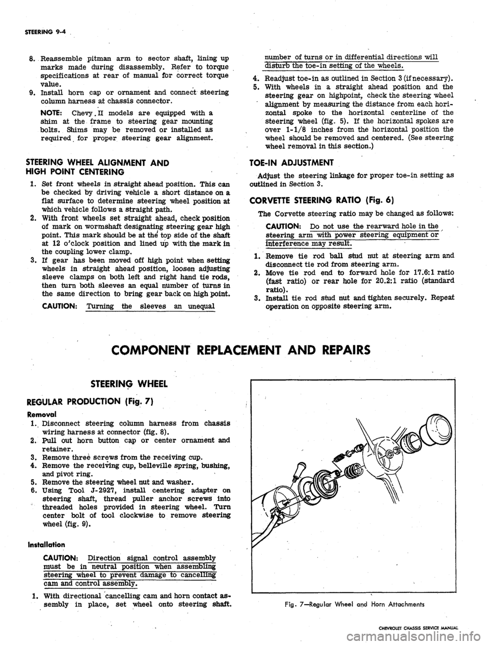
Fig. 7—-Regular Wheel and Horn Attachments
CHEVROLET CHASSIS SERVICE MANUAL