coolant level CHEVROLET CAMARO 1967 1.G Chassis Workshop Manual
[x] Cancel search | Manufacturer: CHEVROLET, Model Year: 1967, Model line: CAMARO, Model: CHEVROLET CAMARO 1967 1.GPages: 659, PDF Size: 114.24 MB
Page 16 of 659
LUBRICATION 0-14
SAE 5W-30 oils may be used during periods when
temperatures of 32° and below are to be expected.
Types of Oils
In service, crankcase oils may form sludge and varnish
and under some conditions, corrosive acids unless pro-
tected against oxidation.
To minimize the formation of these harmful products
and to assure the use of oil best suited for present day
operating conditions, automobile manufacturers have de-
veloped a series of sequence tests designed to evaluate
the ability of any oil to properly lubricate automobile
engines.
It is recommended that only those oils which are
certified by their suppliers as meeting or exceeding the
maximum severity requirements of these sequence tests
(or GM Standard 4745-M) be used in Chevrolet engines.
Certified sequence tested oils will be described as such
on their containers.
Maintaining Oil Level
The oil gauge rod is marked "Full" and "Add Oil."
These notations have broad arrows pointing to the level
lines.
The oil level should be maintained between the
two lines, neither going above the "Full" line nor under
the "Add Oil" line. DO NOT OVERFILL. After operating
vehicle allow a few minutes for oil to return to crankcase
before checking oil level.
Check the oil level frequently and add oil when
necessary.
Oil and Filter Change Intervals
NOTE:
Under prolonged dusty driving condi-
tions,
it is recommended that these operations
be performed more often.
OIL
To insure continuation of best performance, low main-
tenance cost and long engine life, it is necessary to
change the crankcase oil whenever it becomes contami-
nated with harmful foreign materials. Under normal
driving conditions draining the crankcase and refilling
with fresh oil every 60 days or every 6000 miles which-
ever occurs first, is recommended.
It is always advisable to drain the crankcase only after
the engine has become thoroughly warmed up or reached
normal operating temperature. The benefit of draining is,
to a large extent, lost if the crankcase is drained when
the engine is cold, as some of the suspended foreign
material will cling to the sides of the oil pan and will not
drain out readily with the cold, slower moving oil.
OIL FILTER
Change engine oil filter every 6000 miles or every 6
months, whichever occurs first.
NOTE:
For Vehicles in heavy duty operation
involving continuous start-stop or prolonged idl-
ing, engine oil should be changed after 2500-
3000 miles of operation. The filter should be
changed after 5000-6000 miles of operation.
Crankcase Dilution
Probably the most serious phase of engine oil deterio-
ration is that of crankcase dilution which is the thinning
of the oil by fuel vapor leaking by pistons and rings and
mixing with the oil and by condensation of water on the
cylinder walls and crankcase.
Leakage of fuel, or fuel vapors, into the oil pan occurs
mostly during the "warming up" period when the fuel is
not thoroughly vaporized and burned. Water vapor enters
the crankcase through normal engine ventilation and
through exhaust gas blow-by. When the engine is not
completely warmed up, these vapors condense, combine
with the condensed fuel and exhaust gases and form acid
compounds in the crankcase.
As long as the gases and internal walls of the crank-
case are hot enough to keep water vapor from con-
densing, no harm will result. However, when the engine
is run in low temperatures moisture will collect and
unite with the gases formed by combustion resulting in
an acid formation. The acid thus formed is likely to
cause serious etching or pitting which will manifest itself
in excessively rapid wear on piston pins, camshaft
bearings and other moving parts of the engine, oftentimes
causing the owner to blame the car manufacturer or the
lubricating oil when in reality the trouble may be traced
back to the character of fuel used, or a condition of the
engine such as excessive blowby or improper carburetor
adjustment.
Automatic Control Devices to Minimize
Crankcase Dilution
All engines are equipped with automatic devices which
aid greatly in minimizing the danger of crankcase
dUution.
The thermostat, mounted in the cylinder head water
outlet, restricts the flow of water to the radiator until a
predetermined temperature is reached, thus minimizing
the length of time required to reach efficient operating
temperature, reducing the time that engine temperatures
are conducive to vapor condensation.
A water by-pass is included in the cooling system,
utilizing a hole in the front of, the cylinder block. This
allows a limited circulation of coolant, bypassing the
thermostat until thermostat opening temperatures are
reached. This system provides a uniform coolant tem-
perature throughout the engine, eliminating localized
hot-spots, improving exhaust valve life, provides fast
warmrup of lubricating oil and fast temperature rise in
the coolant which provides fast heater operation in cold
weather.
A thermostatic heat control on the exhaust manifold
during the warming up period, automatically directs the
hot exhaust gases against the center of the intake mani-
fold, greatly aids in proper vaporization of the fuel.
An automatic choke reduces the danger of raw or
unvaporized fuel entering the combustion chamber and
leaking into the oil reservoir.
An.
efficient crankcase ventilating system drives off
fuel vapors and aids in the evaporation of the raw fuel
and water which may find its way into the oil pan.
CRANKCASE BREATHER CAP
Clean and re-oil at every oil change..
CHEVROLET CHASSIS SERVICE MANUAL
Page 44 of 659
HEATER AND AIR CONDITIONING 1A-21
"De-Fog"
Position
In the event that the front windshield should require
removal of a fogging condition, the owner at his option
may direct air to the windshield. The "De-Fog" position
directs part of the air to the windshield while retaining a
certain amount through the floor outlets. The temper-
ature of the air remains the same as it was prior to the
control being placed in the "De-Fog" position. Five
blower speeds are available. The temperature of the air
and the blower speed are selected by the automatic
controls and are dependent upon the in-car temperature.
"De-Ice" Position
The "De-Ice" position provides full heat with "Hi"
blower directing the entire airflow to the windshield to
melt ice. The automatic controls are completely defeated
and as a result, full heat with "Hi" blower are the only
conditions that can be received. The system will turn on
immediately in this position even though the engine
coolant might be cold.
General Information
Three start up conditions can be achieved with
Comfortron.
Weather
Cold
Method of Starting System
System starts as soon as engine coolant is
hot.
Hot System starts immediately when AC is
required.
Any System starts immediately in "De-Ice"
position.
UNIVERSAL SYSTEM
A self-contained unit, the dealer installed Universal
System operates on recirculated air only and entirely
independent of the vehicle heater. Recirculated inside air
is drawn into the unit, passed through the evaporator core
and into the car through the adjustable outlets in the
evaporator case. The entire unit mounts compactly
beneath the dash. Temperature control is by means of a
thermostatic switch.
The compressor used with the Universal System is
identical to that used for the Four-Season system except
for displacement. Underhood components are similar in
placement to the Four-Season system.
Controls
Universal system controls are the AIR knob controlling
the three speed blower motor switch and the TEMP knob
which controls the setting of the thermostatic switchi
Switch adjustment is covered elsewhere in this section.
When operating this system the Heater must be fully off.
CHEVY II ALL-WEATHER SYSTEM
The Chevy n All-Weather Air Conditioning System,
Figure 33, operates in conjunction with the heater to
provide a complete air conditioning system operating on
either outside air, recirculated air or a combination of
both. The cooling unit attaches to the heater distributor
and utilizes the heater blower. Several controls allow
full use of either the heating or cooling features of the
system. During marginal weather, it is possible to pro-
vide heated air at floor level and cooled air at breath
level.
A schematic view of the air conditioning underdash
components is provided in Figure 34 to aid in under-
standing airflow and control operation.
The evaporator assembly, located in the passenger
compartment attached directly to the heater distributor,
contains the evaporator core, expansion valve, thermo-
static switch and the air conditioning "ON" knob. The
thermostatic switch, utilized as the cooling control, feels
the temperature of the cooled air leaving the evaporator
core and turns the compressor on and off in accordance
with cooling needs. Refrigerant lines connect the evap-
orator assembly to the other system components located
in the engine compartment.
The six cylinder air conditioning compressor, com-
pletely field serviceable, is bracket-mounted to the
engine and is belt driven from the crankshaft pulley. A
muffler assembly, designed to eliminate compressor
pulsations is an integral part of the compressor con-
nector block. The condenser is mounted on the radiator
support just ahead of the engine radiator. The receiver-
dehydrator, with its sight glass, is located on the right
fender skirt.
Controls
Control of the air conditioning system is achieved
through the use of the heater control on the instrument
panel as well as the two knobs located on the air condi-
tioning unit itself (fig. 35).
Air Conditioning "ON" Knob
Labeled "Pull for Air Cond.", this knob diverts air-
flow from the floor distributor and through the air condi-
tioning unit. Initial movement of this knob also actuates a
switch, located at the damper door, which energizes the
compressor clutch thus putting the system into operation
and under the control of the thermostatic switch.
Temp-Cool Knob
This knob controls the thermostatic switch. Turn the
knob clockwise for more cooling, counter-clockwise for
less cooling.
Air Lever
This lever actuates the damper within the assembly
which chooses between recirculated air or outside air.
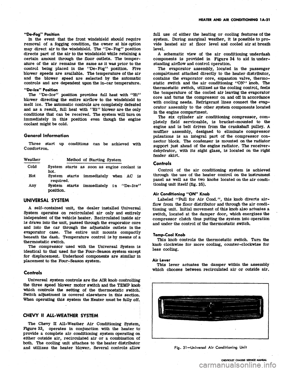
Fig.
31-Universal Air Conditioning Unit
CHEVROLET CHASSIS SERVICE MANUAL
Page 60 of 659
HEATER AND AIR CONDITIONING 1A-37
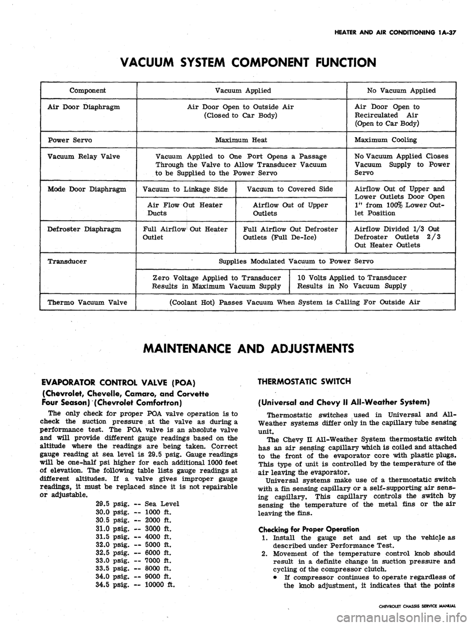
VACUUM SYSTEM COMPONENT FUNCTION
Component
Air Door Diaphragm
Power Servo
Vacuum Relay Valve
Mode Door Diaphragm
Defroster Diaphragm
Transducer
Thermo Vacuum Valve
Vacuum Applied
Air Door Open to Outside Air
(Closed to Car Body)
Maximum Heat
Vacuum Applied to One Port Opens a Passage
Through the Valve to Allow Transducer Vacuum
to be Supplied to the Power Servo
Vacuum to Linkage Side
Air Flow Out Heater
Ducts
Full Airflow Out Heater
Outlet
Vacuum to Covered Side
Airflow Out of Upper
Outlets
Full Airflow Out Defroster
Outlets (Full De-ice)
No Vacuum Applied
Air Door Open to
Re circulated Air
(Open to Car Body)
Maximum Cooling
No Vacuum Applied Closes
Vacuum Supply to Power
Servo
Airflow Out of Upper and
Lower Outlets Door Open
1"
from 100% Lower Out-
let Position
Airflow Divided 1/3 Out
Defroster Outlets 2/3
Out Heater Outlets
Supplies Modulated Vacuum to Power Servo
Zero Voltage Applied to Transducer
Results in Maximum Vacuum Supply
10 Volts Applied to Transducer
Results in No Vacuum Supply
(Coolant Hot) Passes Vacuum When System is Calling For Outside Air
MAINTENANCE AND ADJUSTMENTS
EVAPORATOR CONTROL VALVE (POA)
(Chevrolet, Chevelle, Comoro, and Corvette
Four Season) (Chevrolet Comfortron)
The only check for proper POA valve operation is to
check the suction pressure at the valve as during a
performance test. The POA valve is an absolute valve
and will provide different gauge readings based on the
altitude where the readings are being taken. Correct
gauge reading at sea level is 29.5 psig. Gauge readings
will be one-half psi higher for each additional 1000 feet
of elevation. The following table lists gauge readings at
different altitudes. If a valve gives improper gauge
readings, it must be replaced since it is not repairable
or adjustable.
29.5
30.0
30.5
31.0
31.5
32.0
32.5
33.0
33.5
34.0
34.5
psig.
psig.
psig.
psig.
psig.
psig.
psig.
psig.
psig.
psig.
psig.
— Sea 1
— 1000
— 2000
— 3000
— 4000
— 5000
— 6000
— 7000
— 8000
— 9000
Level
ft.
ft.
ft.
ft.
ft.
ft.
ft.
ft.
ft.
— 10000 ft.
THERMOSTATIC SWITCH
(Universal and Chevy II All-Weather System)
Thermostatic switches used in Universal and All-
Weather systems differ only in the capillary tube sensing
unit.
The Chevy n All-Weather System thermostatic switch
has an air sensing capillary which is coiled and attached
to the front of the evaporator core with plastic plugs.
This type of unit is controlled by the temperature of the
air leaving the evaporator.
Universal systems make use of a thermostatic switch
with a fin sensing capillary or a self-supporting air sens-
ing capillary. This capillary controls the switch by
sensing the temperature of the metal fins or the air
leaving the fins.
Checking for Proper Operation
1.
Install the gauge set and set up the vehicle as
described under Performance Test.
2.
Movement of the temperature control knob should
result in a definite change in suction pressure and
cycling of the compressor clutch.
• If compressor continues to operate regardless of
the knob adjustment, it indicates that the points
CHEVROLET CHASSIS SERVICE MANUAL
Page 271 of 659
ENGINE 6-6
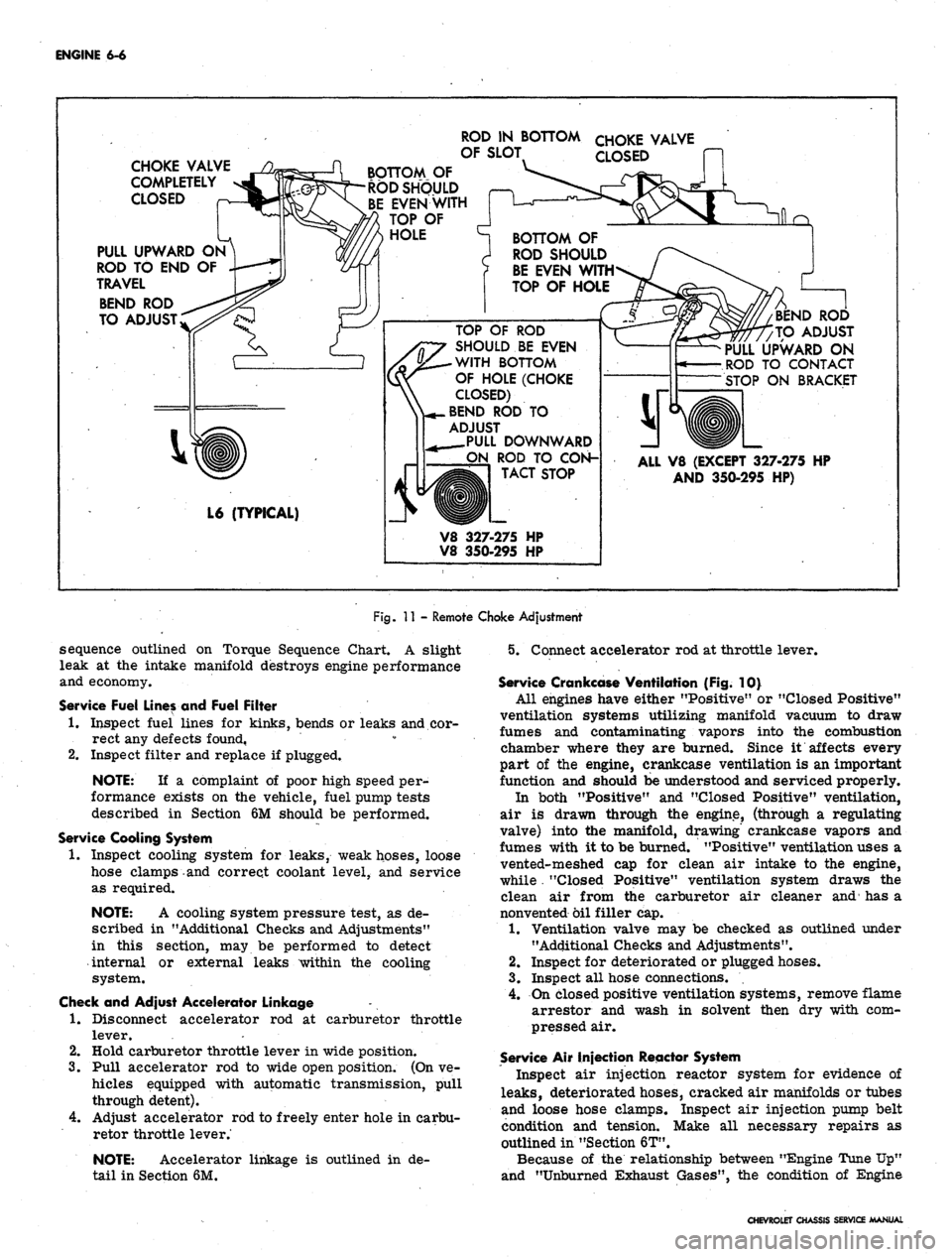
CHOKE VALVE
COMPLETELY
CLOSED
PULL UPWARD ON
ROD TO END OF
TRAVEL
BEND ROD
TO ADJUST
ROD IN BOTTOM
OF SLOT
BOTTOM OF
ROD SHOULD
EVENWITH
TOP OF
HOLE
CHOKE VALVE
CLOSED
BOTTOM OF
ROD SHOULD
BE EVEN WITH
TOP OF HOLE
TOP OF ROD
SHOULD BE EVEN
WITH BOTTOM
OF HOLE (CHOKE
CLOSED)
^..BEND ROD TO
ADJUST
_PULL DOWNWARD
ON ROD TO CON-
TACT STOP
L6 (TYPICAL)
V8 327-275 HP
V8 350-295 HP
BEND ROI
TO ADJUST
PULL UPWARD ON
ROD TO CONTACT
STOP ON BRACKET
ALL V8 (EXCEPT 327-275 HP
AND 350-295 HP)
Fig.
11 - Remote Choke Adjustment
sequence outlined on Torque Sequence Chart. A slight
leak at the intake manifold destroys engine performance
and economy.
Service Fuel Lines and Fuel Filter
1.
Inspect fuel lines for kinks, bends or leaks and cor-
rect any defects found, • • •
2.
Inspect filter and replace if plugged.
NOTE:
If a complaint of poor high speed per-
formance exists on the vehicle, fuel pump tests
described in Section 6M should be performed.
Service Cooling System
1.
Inspect cooling system for leaks, weak hoses, loose
hose clamps and correct coolant level, and service
as required.
NOTE:
A cooling system pressure test, as de-
scribed in "Additional Checks and Adjustments"
in this section, may be performed to detect
internal or external leaks within the cooling
system.
Check and Adjust Accelerator Linkage
1.
Disconnect accelerator rod at carburetor throttle
lever.
2.
Hold carburetor throttle lever in wide position.
3.
Pull accelerator rod to wide open position. (On ve-
hicles equipped with automatic transmission, pull
through detent).
4.
Adjust accelerator rod to freely enter hole in carbu-
retor throttle lever.'
NOTE:
Accelerator linkage is outlined in de-
tail in Section 6M.
5. Connect accelerator rod at throttle lever.
Service Crankcase Ventilation (Fig. 10}
All engines have either "Positive" or "Closed Positive"
ventilation systems utilizing manifold vacuum to draw
fumes and contaminating vapors into the combustion
chamber where they are burned. Since it affects every
part of the engine, crankcase ventilation is an important
function and should be understood and serviced properly.
In both "Positive" and "Closed Positive" ventilation,
air is drawn through the engine, (through a regulating
valve) into the manifold, drawing' crankcase vapors and
fumes with it to be burned. "Positive" ventilation uses a
vented-meshed cap for clean air intake to the engine,
while . "Closed Positive" ventilation system draws the
clean air from the carburetor air cleaner and has a
nonvented oil filler cap.
1.
Ventilation valve may be checked as outlined under
"Additional Checks and Adjustments".
2.
Inspect for deteriorated or plugged hoses.
3.
Inspect all hose connections.
4.
On closed positive ventilation systems, remove flame
arrestor and wash in solvent then dry with com-
pressed air.
Service Air Injection Reactor System
Inspect air injection reactor system for evidence of
leaks,
deteriorated hoses, cracked air manifolds or tubes
and loose hose clamps. Inspect air injection pump belt
condition and tension. Make all necessary repairs as
outlined in "Section 6T".
Because of the relationship between "Engine Tune Up"
and "Unburned Exhaust Gases", the condition of Engine
CHEVROLET CHASSIS SERVICE MANUAL
Page 306 of 659
SECTION 6K
ENGINE COOLING
INDEX
Page
General Description . . . 6K-1
Maintenance and Adjustments 6K-1
Coolant Level 6K-1
Coolant System Checks 6K-1
Periodic Maintenance 6K-2
Cleaning 6K-2
Reverse Flushing 6K-2
Radiator 6K-2
Page
Cylinder Block and Cylinder Head 6K-2
Hot Water Heater 6K-2
Fan Belt . 6K-2
Adjustment ....". 6K-2
Thermostat . 6K-2
Replacement 6K-2
Water Pump. . . . 6K-3
Removal 6K-3
Installation 6K-3
GENERAL DESCRIPTION
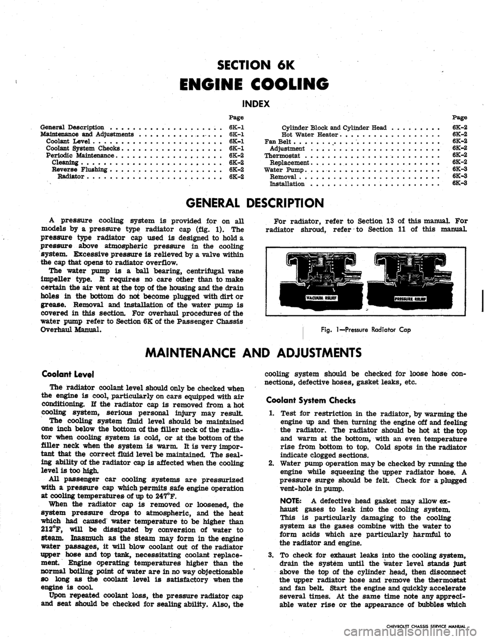
A pressure cooling system is provided for on all
models by a pressure type radiator cap (fig. 1). The
pressure type radiator cap used is designed to hold a
pressure above atmospheric pressure in the cooling
system. Excessive pressure is relieved by a valve within
the cap that opens to radiator overflow.
The water pump is a ball bearing, centrifugal vane
impeller type. It requires no care other than to make
certain the air vent at the top of the housing and the drain
holes in the bottom do not become plugged with dirt or
grease. Removal and installation of the water pump is
covered in this section. For overhaul procedures of the
water pump refer to Section 6K of the Passenger Chassis
Overhaul Manual.
For radiator, refer to Section 13 of this manual For
radiator shroud, refer to Section 11 of this manual.
Fig.
I—Pressure Radiator Cap
MAINTENANCE AND ADJUSTMENTS
Coolant Level
The radiator coolant level should only be checked when
the engine is cool, particularly on cars equipped with air
conditioning. If the radiator cap is removed from a hot
cooling system, serious personal injury may result
The cooling system fluid level should be maintained
one inch below the bottom of the filler neck of the radia-
tor when cooling system is cold, or at the bottom of the
filler neck when the system is warm. It is very impor-
tant that the correct fluid level be maintained. The seal-
ing ability of the radiator cap is affected when the cooling
level is too high.
All passenger car cooling systems are pressurized
with a pressure cap which permits safe engine operation
at cooling temperatures of
up
to 247°F.
When the radiator cap is removed or loosened, the
system pressure drops to atmospheric, and the heat
which had caused water temperature to be higher than
212°F, will be dissipated by conversion of water to
steam. Inasmuch as the steam may form in the engine
water passages, it will blow coolant out of the radiator
upper hose and top tank, necessitating coolant replace-
ment Engine operating temperatures higher than the
normal boiling point of water are in no way objectionable
so long as the coolant level is satisfactory when the
engine is cooL
Upon repeated coolant loss, the pressure radiator cap
and seat should be checked for sealing ability. Also, the
cooling system should be checked for loose hose con-
nections, defective hoses, gasket leaks, etc.
Coolant System Checks
1.
Test for restriction in the radiator, by warming the
engine up and then turning the engine off and feeling
the radiator. The radiator should be hot at the top
and warm at the bottom, with an even temperature
rise from bottom to top. Cold spots in the radiator
indicate clogged sections.
2.
Water pump operation may be checked by running the
engine while squeezing the upper radiator hose. A
pressure surge should be felt Check for a plugged
vent-hole in pump.
NOTE:
A defective head gasket may allow ex-
haust gases to leak into the cooling system.
This is particularly damaging to the cooling
system as the gases combine with the water to
form acids which are particularly harmful to
the radiator and engine.
3.
To check for exhaust leaks into the cooling system,
drain the system until the water level stands just
above the top of the cylinder head, then disconnect
the upper radiator hose and remove the thermostat
and fan belt. Start the engine and quickly accelerate
several times. At the same time note any appreci-
able water rise or the appearance of bubbles which
CHEVROLET CHASSIS SERVICE MANUAL
Page 307 of 659

ENGINE COOLING 6K-2
are indicative of exhaust gases leaking into the coolr
ing system.
Periodic Maintenance
Periodic service must be performed to the engine cool-
ing system to keep it in efficient operating condition.
These services should include a complete cleaning and
reverse flushing as well as a reconditioning service.
In the course of engine operation, rust and scale ac-
cumulate in the radiator and engine water jacket. The
accumulation of these deposits can be kept to a minimum
by the use of a good rust inhibitor but it should be
remembered that an inhibitor will not remove rust al-
ready present in the cooling system.
Two common causes of corrosion are: (1) air suction--
Air may be drawn into the system due to low liquid level
in the radiator, leaky water pump or loose hose con-
nections; (2) exhaust gas leakage—Exhaust gas may be
blown into the cooling system past the cylinder head
gasket or through cracks in the cylinder head and block.
Cleaning
A good cleaning solution should be used to loosen the
rust and scale before reverse flushing the cooling
system. There are a number of cleaning solutions avail-
able and the manufacturer's instructions with the particu-
lar cleaner being used should always be followed.
An excellent preparation to use for this purpose is GM
Cooling System Cleaner. The following directions for
cleaning the system applies only when this type cleaner
is-used.
1.
Drain the cooling system including the cylinder block
and then close both drain plugs.
2.
Remove thermostat and replace thermostat housing.
3.
Add the liquid portion (No. 1) of the cooling system
cleaner.
4.
Fill the cooling system with water to a level of about
3 inches below the top of the overflow pipe.
5. Cover the radiator and run the engine at moderate
speed until engine coolant temperature reaches 180
degrees.
6. Remove cover from radiator and continue to run the
engine for 20 minutes. Avoid boiling.
7. While the engine is still running, add the powder
portion (No. 2) of the cooling system cleaner and
continue to run the engine for 10 minutes.
8. At the end of this time, stop the engine, wait a few
minutes and then open the drain cocks or remove
pipe plugs. Also remove lower hose connection.
CAUTION: Be careful not to scald your hands.
NOTE:
Dirt and bugs may be cleaned out of
the radiator air passages by blowing out with air
pressure from the back of the core.
Reverse Flushing
Reverse flushing should always be accomplished after
the system is thoroughly cleaned as outlined above.
Flushing is. accomplished through the system in a direc-
tion opposite to the normal flow. This action causes the
water to get behind the corrosion deposits and force
them out.
Radiator
1.
Remove the upper and lower radiator hoses and re-
place the radiator cap,
2.
Attach a lead-away hose at the top of the radiator.
3.
Attach a new piece of hose to the radiator outlet
connection and insert the flushing gun in this hose.
4.
Connect the water hose of the flushing gun to a water
outlet and the air hose to an air line.
5. Turn on the water and when the radiator is full, turn
on the air in short blasts, allowing the radiator to
fill between blasts of air.
CAUTION: Apply air gradually as a clogged
radiator will stand only a limited pressure.
6. Continue this flushing until the water from the lead-
away hose runs clear.
Cylinder Block and Cylinder Head
1.
With the thermostat removed, attach a lead-away
hose to the water pump inlet and a length of new hose
to the water outlet connection at the top of the engine.
NOTE:
Disconnect the heater hose when re-
verse flushing engine.
2.
Insert the flushing gun in the new hose.
3.
Turn on the water and when the engine water jacket
is full, turn on the air in short blasts.
4.
Continue this flushing until the water from the lead-
away hose runs clear.
Hot Water Heater
1.
Remove water outlet hose from heater core pipe.
2.
Remove inlet hose from engine connection.
3.
Insert flushing gun and flush heater core. Care must
be taken when applying air pressure to prevent
damage to the core.
Fan Belt
Adjustment
1.
Loosen bolts at Delcotron slotted bracket.
2.
Pull Delcotron away from engine until desired ten-
sion reading is obtained with a strand tension gauge.
Refer to Section 6, "Engine Tune-Up".
3.
Tighten all Delcotron bolts securely.
Thermostat
The thermostat consists of a restriction valve actuated
by a thermostatic element. This is mounted in the hous-
ing at the cylinder head water outlet above the water
pump,
thermostats are designed to open and close at
predetermined temperatures and if not operating properly
should be removed and tested as follows.
Replacement
1.
Remove radiator to water outlet hose.
2.
Remove thermostat housing bolts and remove water
outlet and gasket from thermostat housing (fig. 2).
3.
Inspect thermostat valve to make sure it is in good
condition.
4.
Place thermostat in hot water 25° above the temper-
ature stamped on the thermostat valve.
5. Submerge the valve completely and agitate the water
thoroughly. Under this condition the valve should
open fully.
6. Remove the thermostat and place in water 10° below
temperature indicated on the valve.
7. With valve completely submerged and water agitated
thoroughly, the valve should close completely.
8. If thermostat checks satisfactorily, re-install, using
a new housing gasket.
9. Refill cooling system.
CHEVROLET CHASSIS SERVICE MANUAL
Page 538 of 659
ELECTRICAL-BODY
AND
CHASSIS
12-26
•
Low oil
pressure
• High engine temperature
• Defective wiring
or
switch
connector from sender
in block above starter
on
and
at
left front
of
distributor
on V-8
Sending Unit Replacement
1.
Disconnect wiring harness
unit terminal (located
L-6 engines
engines).
2.
Remove sender unit using Tool J-21757
or 12
point
socket, replace with
new
unit
and
check operation.
GENERATOR INDICATOR
1.
Ignition
on,
Engine
not
Running
and
Telltale Light
Off.
• Indicator bulb burned out, replace bulb.
• Open circuit
or
loose connection
in the
telltale
light circuit.
2.
telltale Light Stays
on
after Engine
is
Started.
If indicator light does
not go out at
engine idle
speed, refer
to
Charging Systems under Engine
Electrical, Section
6Y.
TEMPERATURE (COOLING SYSTEM) INDICATOR
The temperature indicator circuit consists
of two re-
motely located units, indicator gauge
and
engine sender
unit.
The
indicator gauge, located
in the
instrument
panel, consists
of a
red light which will indicate
an
over-
heated engine condition.
Engine Sender Unit Replacement
1.
Drain engine cooling system
to a
level below unit.
2.
Remove sender unit (located
in the
inlet manifold
near water pump housing
on V-8
engines and
in the
cylinder head near
an
exhaust port
oh L-6
engines)
and replace with new unit.
3.
Refill cooling system
and
check operation
of
unit.
CHEVELLE INSTRUMENTS AND GAUGES
INDEX
Page
General Description
* *
i2-26
Service Operations
12-26
Instrument Panel
12-26
Instrument Cluster.
12-26
Fuel Gauge and/or Ammeter
12-27
Clock,
i 12-27
Speedometer
12-27
Page
Speedometer Cable
.
. 12-27
Temperature Gauge
12-29
Oil Pressure Gauge
12-29
Indicator Lights.
. 12-29
Oil Pressure Indicator
12-29
Generator Indicator
. . 12-29
• Temperature Indicator
12-29
GENERAL DESCRIPTION
The Chevelle instrument cluster assembly consists
of:
a speedometer;
a
fuel gauge;
a
generator,
an
engine
tem-
perature and an
oil
pressure indicator lamp, and includes
a clock
on
deluxe models.
On
super sport models,
am-
meter, coolant temperature
and oil
pressure gauges
re-
place
the
appropriate indicator lights. Except
for the
speedometer,
all of the
indicator lamps, instruments
and
gauges
of
these clusters may
be
serviced without remov-
ing
the
instrument cluster assembly from
the
vehicle.
In addition
to the
instrument indicator lamps,
a
brake
warning lamp
is
included
in the
cluster
as
standard
equipment.
The
indicator
is
connected
to the
parking
brake
and
brake pressure differential switches
and
serves
a
dual function.
It
lights when the parking brake
is applied
and
also when
the
brake pedal
is
applied,
if a
malfunction should occur
in the
brake system
due to a
loss
of
hydraulic pressure. Servicing
of the
hydraulic
pressure differential switch
is
covered
in
Section
5 of
this manual.
Regular maintenance
is not
required on the instrument
cjLuster
or its
components other than maintaining dean
and tight electrical connections, replacing defective parts
and keeping
the
speedometer cable properly lubricated.
SERVICE OPERATIONS
INSTRUMENT PANEL ASSEMBLY
INSTRUMENT CLUSTER (Figs.
41
thru
44)
Removal
1.
Disconnect battery ground cable.
2.
Remove steering coupling bolt and disconnect steer-
ing shaft from coupling.
3.
Loosen mast jacket lower clamp.
4.
Remove
air
conditioning center distributor duct
(if
so equipped).
5. Remove radio rear support bracket screw.
6. Remove mast jacket upper support clamp and retain-
ing bolts from lower support (refer
to
Section
9,
Steering).
CAUTION: Cover mast jacket
and
parl
brake handle with
a
suitable material
to
prevc
scratching.
7.
Disconnect speedometer cable
at
rear
of
cluster
housing
and
speed warning control knob
at
panel
(if
so equipped).
8. Remove instrument panel retaining screws (nine
upper and five lower).
.
9. Working under the console remove four lower retain-
ing screws from instrument cluster housing.
10.
Pull instrument panel assembly from console and
lay
forward on mast jacket.
11.
Disconnect wiring harness, cluster lamps and wiring
CHEVROLET CHASSIS SERVICE MANUAL
Page 548 of 659
ELECTRICAL-BODY
AND
CHASSIS
12-36
CAMARO INSTRUMENTS AND GAUGES
INDEX
Page
General Description
12-36
Service Operations
12-36
Instrument Cluster
. . . 12-36
Instrument Lamps
12-36
Printed Circuit
12-36
Fuel Gauge
12-37
Tachometer
. . 12-37
Seat Separator Instrument Console
12-37
Page
Fuel Gauge
12-37
Ammeter
12-37
Temperature Gauge
12-37
Oil Pressure Gauge
. 12-37
Fuel Warning Unit
12-37
Clock.
... 12-37
Oil Pressure Indicator
12-37
Generator Indicator
12-38
Temperature Indicator
12-38
GENERAL DESCRIPTION
The standard Camaro instrument cluster assembly con-
sists
of two
circular units which house
the
speedometer
and fuel gauge assemblies.
The oil
pressure, left-hand
directional
and
brake warning indicators
are
located
in
the face
of the
speedometer bezel while generator,
tem-
perature
and
right-hand directional indicators are grouped
with
the
fuel gauge unit.
The
high beam indicator
is
located between
the
cluster bezels.
A special instrumentation package
is
available with
the
eight-cylinder engine
and
center floor console combina-
tion.
The
special cluster includes:
a
clock; coolant
temperature,
oil
pressure, fuel
and
ammeter gauges,
mounted forward
on the
seat separator console;
a ta-
chometer
in the
right circular housing
of the
dash
in-
strument cluster; and
a low
fuel level indicator replacing
the
oil
pressure indicator lamp
in the
instrument cluster.
The instruments
and
gauges,
may be
serviced only
after
the
instrument cluster
is
removed from
the
vehicle.
Indicator
and
cluster lamps except
for the
high beam
indicator
may be
replaced without removing
the
cluster
assembly. Partial cluster removal
is
necessary when
replacing
the
high beam indicator due
to its
proximity
to
the upper brace
rod
anchor plate.
The
bulbs
are in-
stalled
in
plastic sockets which lock into
the
cluster
housing and make contact with
the
printed circuit.
A
low
level fuel warning system
is a
special feature
available with
the
floor console gauge pack. This
sys-
tem includes
an
indicator lamp
in the
dash cluster and
a
semi-conductor unit senses
the
change
in
electrical
re-
sistance
of the
fuel system circuitry
as
variations
in
fuel level occur.
The
sensing device
is
replaced
as a
unit
if
found defective.
The brake warning light serves
a
dual purpose.
It
functions
as an
indicator when
the
parking brake
is ap-
plied
and
also
if
there
is a
malfunction (loss
of
hydraulic
pressure)
in the
brake system. Switches which provide
the signal
to
operate
the
light
are
located
at the
parking
brake assembly
and at the
brake master cylinder
in the
hydraulic lines. Service
of the
brake pressure differ-
ential switch unit
is
covered
in
Section
5 of
this manual.
Regular maintenance
is not
required on
the
instrument
cluster
or its
components other than maintaining clean,
tight electrical connections, replacing defective parts
and keeping
the
speedometer properly lubricated.
SERVICE OPERATIONS
INSTRUMENT CLUSTER (Figs.
50
thru
53)
Removal
and
Installation
1.
Disconnect battery ground cable.
2.
Remove mast jacket lower support screws
at toe
pan.
3.
Remove mast jacket upper support bolts
and
allow
steering wheel
to
rest
on
seat cushion.
CAUTION: Both supports must
be
detached
to
prevent distortion
of
mast jacket.
4.
Remove cluster attaching screws from face
of
panel
and partially remove assembly from console opening.
5. Reaching behind cluster assembly, disconnect speed-
ometer cable, speed warning device
(if so
equipped
-
Fig.
51) and
chassis harness connector
at
rear
of
panel.
6. Remove assembly from console opening to
a
suitable
bench area
for
required service operations.
7.
To
install, reverse removal procedure.
INSTRUMENT CLUSTER LAMP REPLACEMENT
1.
Turn bulb holder counterclockwise
and
pull
out to
remove from
the
cluster housing.
2.
Pull bulb straight out
to
remove from socket.
3.
Press replacement bulb inward
to
lock
in
socket.
4.
Insert lamp assembly into housing, with lugs
on
holder entering notches
in
housing,
and
turn clock-
wise
to
lock
in
place.
PRINTED CIRCUIT REPLACEMENT
1.
Remove instrument cluster
as
previously described
in this section.
2.
Remove
all
cluster illuminating and indicator lamps
from housing.
3.
Remove fuel gauge terminal nuts
or
tachometer
re-
taining nuts securing printed circuit
to
housing.
4.
Remove four
hex
head screws retaining printed
cir-
cuit
to the
cluster housing
and
remove circuit from
housing.
5.
To
install, reverse removal procedure.
CAUTION:
The
retaining screws
are
part
of
the grounding circuit
and
must
be
installed
to
provide proper connections
for the
printed
eir-
cuit.
CHEVROLET CHASSIS SERVICE MANUAL