charging CHEVROLET CAMARO 1967 1.G Chassis Owner's Manual
[x] Cancel search | Manufacturer: CHEVROLET, Model Year: 1967, Model line: CAMARO, Model: CHEVROLET CAMARO 1967 1.GPages: 659, PDF Size: 114.24 MB
Page 334 of 659
ENGINE-ELECTRICAL 6Y-9
63 AMP 1
MODELS ONLY'
BATTERY FUSIBLE
LINK
HORN
FUSIBLE LINK'
TRANSISTOR
FUSIBLE LINK'
Fig.
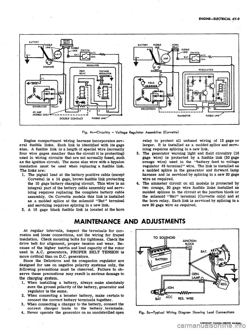
4c— Circuitry - Voltage Regulator Assemblies (Corvette)
Engine compartment wiring harness incorporates sev-
eral fusible links. Each link is identified with its gage
size. A fusible link is a length of special wire (normally
four wire gages smaller than the circuit it is protecting)
used in wiring circuits that are not normally fused, such
as the ignition circuit. The same size wire with a hypalon
insulation must be used when replacing a fusible link.
The links are:
1.
The pigtail lead at the battery positive cable (except
Corvette) is a 14 gage, brown fusible link protecting
the 10 gage battery charging circuit. This wire is an
integral part of the battery cable assembly and serv-
icing requires replacing the complete battery cable
assembly. On Corvette models this link is installed
as a molded splice at the solenoid "Bat" terminal
and servicing requires splicing in a new link.
2.
A 16 gage black fusible link is located at the horn
4.
relay to protect all unfused wiring of 12 gage or
larger. It is installed as a molded splice and serv-
icing requires splicing in a new link.
The generator warning light and field circuitry (16
gage wire) is protected by a fusible link (20 gage
orange wire) used in the "battery feed to voltage
regulator #3 terminal" wire. The link is installed as
a molded splice in the generator and forward lamp
harness and is serviced by splicing in a new 20 gage
wire as required.
The ammeter circuit on all models is protected by
two orange, 20 gage wire fusible links installed as
molded splices in the circuit at the junction block or
the solenoid "Bat" terminal (Corvette only) and at
the horn relay. Each link is serviced by splicing in a
new 20 gage wire as required.
MAINTENANCE AND ADJUSTMENTS
At regular intervals, inspect the terminals for cor-
rosion an4 loose connections, and the wiring for frayed
insulation. Check mounting bolts for tightness. Check the
drive belt for alignment, proper tension and wear. Be-
cause of the higher inertia and load capacity of the rotor
used in A.C. generators, PROPER BELT TENSION is
more critical than on D.C. generators.
Since the Delcotron and its companion regulator are
designed for use on negative polarity systems only, the
following precautions must be observed. Failure to ob-
serve these precautions may result in serious damage to
the charging system.
1.
When installing a battery, always make absolutely
sure the ground polarity of the battery, generator and
regulator is the same.
2.
When connecting a booster battery, make certain to
connect the correct battery terminals together.
3.
When connecting a charger to the battery, connect the
correct charger leads to the battery
%
terminals.
4.
Never operate the generator on an uncontrolled open
TO SOLENOID
BAT ACC RES. WIRE
Fig.
5c—Typical Wiring Diagram Showing Lead Connections
CHEVROLET CHASSIS SERVICE MANUAL
Page 335 of 659
ENGINE-ELECTRICAL 6Y-10
circuit. Make absolutely certain all connections in
the circuit are secure.
5.
Do not short across or ground any of the terminals
on the generator or regulator.
6. Do not attempt to polarize the generator.
7.
Do not disconnect lead at generator without first dis-
connecting battery ground cable.
Trouble in the A.C. charging system will usually be
indicated by one or more of the following conditions:
1.
Faulty indicator lamp or ammeter operation.
2.
An undercharged battery (usually evidenced by slow
cranking speeds).
3.
An overcharged battery (usually evidenced by exces-
sive battery water usage).
4.
Excessive generator noise or vibration.
Described below are a series of on-the-vehicle quick
checks which are designed to assist the service tech-
nician in locating troubles within the various components
of the engine electrical system. Additional checks, ad-
justments and overhaul procedures of these components
are also described in the "Charging Systems—Service
Operations Section" and should be referred to as
necessary.
STATIC CHECKS
Before making any electrical checks, perform the fol-
lowing static checks:
1.
Check for loose fan belt.
2.
Check for defective battery. (Refer to Battery).
3.
Inspect all connections, including the slip-on con-
nectors at the regulator and Delcotron.
NOTE: Do not short field to ground to check if
generator is charging since this will seriously
damage the charging system.
SYSTEM CONDITION TEST
This test is used .to indicate the overall condition of the
charging system (both good and defective) and to isolate
the malfunctioning unit if the system is defective.
NOTE: On Corvette models difficulty may be
encountered -when attempting to make the re-
quired test connections at the voltage regulator.
It is advisable to remove the regulator from its
mounting location to perform the necessary con-
nections at the regulator for the following tests
but make sure unit is grounded.
1.
With ignition off, perform the prescribed Static
Checks outlined in this section. Then set hand brake
and shift transmission
into
neutral.
2.
Connect a voltmeter from junction block relay to
ground at regulator base.
CAUTION: Be sure meter clip does not touch a
resistor or terminal extension under regulator,
3.
Connect a tachometer on engine.
4.
Models equipped with Indicator Lamp: Turn ignition
switch on "ON" position and check indicator lamp.
If lamp fails to glow, perform appropriate tests and
corrections (Indicator Lamp Circuit Tests) before
continuing.
Models equipped with Ammeter: Turn ignition
switch to "ACC" with an accessory on and check
ammeter. If ammeter fails to read discharge, check
ammeter circuit before continuing.
5.
Models equipped with Indicator Lamp: If lamp glows,
start the engine and run' it at 1500 rpm or above.
Check indicator lamp. If lamp fails to go out, per-
form appropriate test and corrections (Indicator
Lamp Circuit Test) before continuing.
Models equipped with Ammeter: If ammeter reads
discharge, start the engine and observe ammeter. If
meter fails to move toward charge (from original
position), perform appropriate test and corrections
(Field Circuit Tests) before continuing.
NOTE: At this point a field circuit has been
established and any other problem will lie in
generator or regulator.
6. Turn on high-beam headlights and heater blower
motor to high speed, run engine at or above 1500
rpm (for a few minutes, if necessary) and read the
voltage on meter.
AIR GAP
ADJUSTING NUT
ONLY
ADJUSTING SCREW
(Turn To Adjust
Voltage Setting)
Fig.
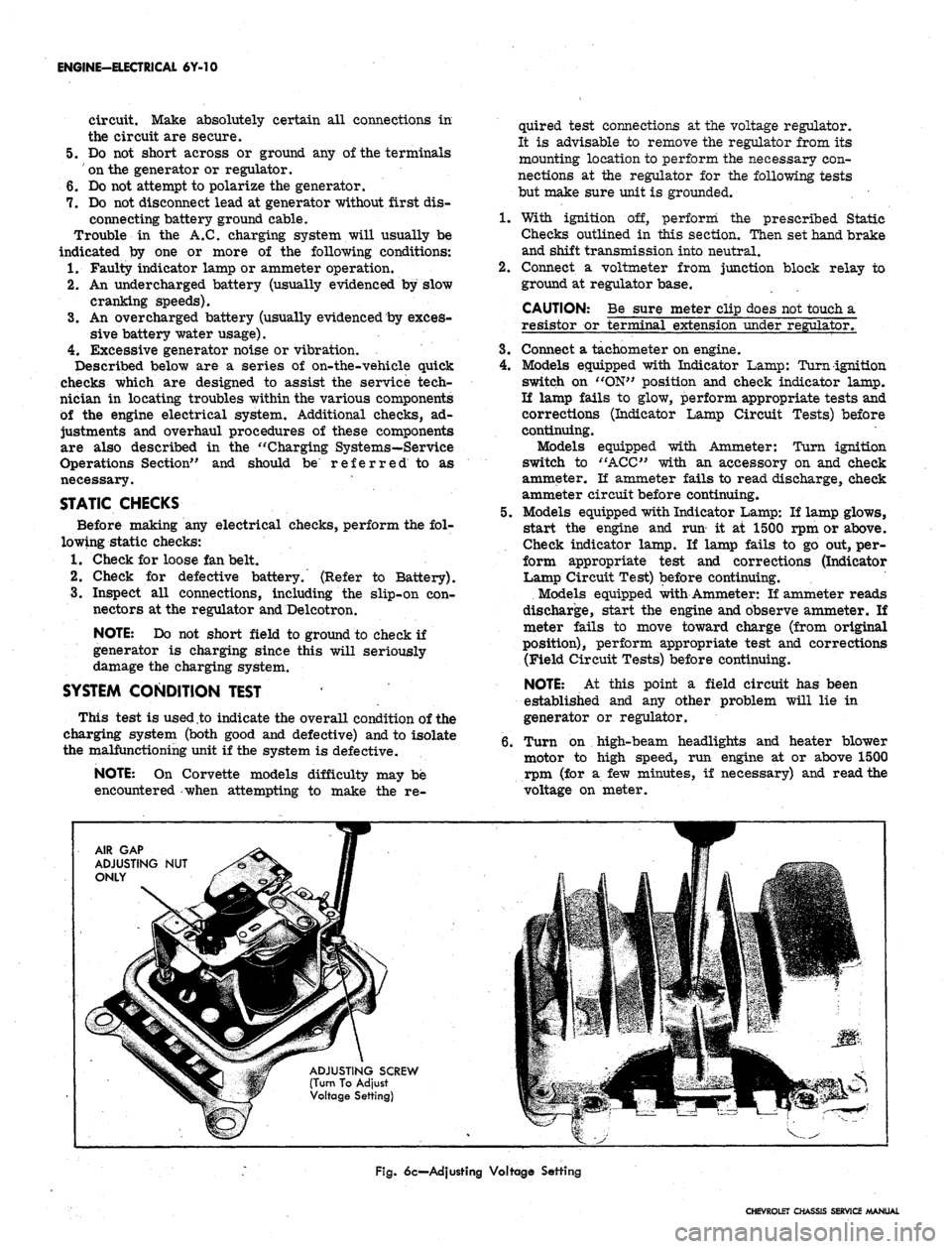
6c—Adjusting Voltage Setting
CHEVROLET CHASSIS SERVICE MANUAL
Page 336 of 659
ENGINE-ELECTRICAL 6Y-11
I
BAT
JUNCTION BLOCK
DELCOTRON
—GRQ
BATTERY
&HJVVWV
0 VA OHM TEST RELAY >
RESISTOR [ 1 d
FUSIBLE
LINK
TO CRANKING
MOTOR
Ik
REGULATOR
VOLTMETER
FUSIBLE LINK
IGN.
SWITCH
Fig.
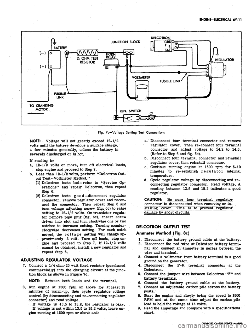
7c—Voltage Setting Test Connections
NOTE:
Voltage will not greatly exceed 12-1/2
volts until the battery develops a surface charge,
a few minutes generally, unless the battery is
severely discharged or is hot.
If reading is:
a. 12-1/2 volts or more, turn off electrical loads,
stop engine and proceed to Step 7.
b.
Less than 12-1/2 volts, perform "Delcotron Out-
put Test-Voltmeter Method."
(1) Delcotron tests bad—refer to "Service Op-
erations" and repair Delcotron, then repeat
Step 6.
(2) Delcotron tests good—disconnect regulator
connector, remove regulator cover and recon-
nect the connector. Then repeat Step 6 and
turn voltage adjusting screw (fig. 6c) to raise
setting to 12-1/2 volts. On transistor regula-
tor remove pipe plug (fig. 6c), insert screw
driver into slot and turn clockwise one or two
notches to increase setting. Turning counter-
clockwise decreases setting. For each notch
moved, the voltage setting will change ap-
proximately .3 volt. Turn off loads, stop en-
gine and proceed to Step 7. If 12-1/2 volts
cannot be obtained, install a new regulator and
repeat Step 6.
ADJUSTING REGULATOR VOLTAGE
7. Connect a 1/4 ohm-25 watt fixed resistor (purchased
commercially) into the charging circuit at the junc-
tion block as shown in Figure 7c.
NOTE:
Between both leads and the terminal.
8. Run engine at 1500 rpm or above for at least 15
minutes of warm-up, then cycle regulator voltage
control (by disconnecting and re-connecting regulator
connector) and read voltage.
If voltage is 13.5 to 15.2, the regulator is okay.
If voltage is not within 13.5 to 15.2 volts, leave en-
gine running at 1500 rpm or above and:
a. Disconnect four terminal connector and remove
regulator cover. Then re-connect four terminal
connector and adjust voltage to i4.2 to 14.6.
(Refer to Step 6 and fig. 6c).
b.
Disconnect four terminal connector and reinstall
regulator cover, then reinstall connector.
c. Continue running engine at 1500 rpm for 5-10
minutes to re-establish regulator internal
temperature.
d. Cycle regulator voltage by disconnecting and re-
connecting regulator connector. Read voltage. A
reading between 13.5 and 15.2 indicates a good
regulator.
CAUTION: Be sure four terminal regulator
connector is disconnected when removing or in-
stalling cover. This is to prevent regulator
damage by short circuits.
DELCOTRON OUTPUT TEST
Ammeter Method (Fig. 8c)
1.
Disconnect the battery ground cable at the battery.
2.
Disconnect the red wire at Delcotron battery termi-
nal and connect an ammeter in series between the
wire and terminal.
3.
Connect a voltmeter from battery terminal to a good
ground on the generator.
4.
Disconnect the F-R terminal connector at the
Delcotron.
5. Connect the jumper wire between Delcotron "F" and
battery terminals.
6. Connect the battery ground cable at the battery.
7. Connect an adjustable carbon pile across the battery
posts.
8. Start the engine and slowly bring the speed to 1500
RPM and at the same time adjust the carbon pile
load to hold the voltage at 14 volts.
9. Read the amperage and compare with a specifications
chart.
CHEVROLET CHASSIS SERVICE MANUAL
Page 339 of 659
ENGINE-ELECTRICAL 6Y-14
VOLTMETER
WIRING HARNESS
CONNECTOR
Fig.
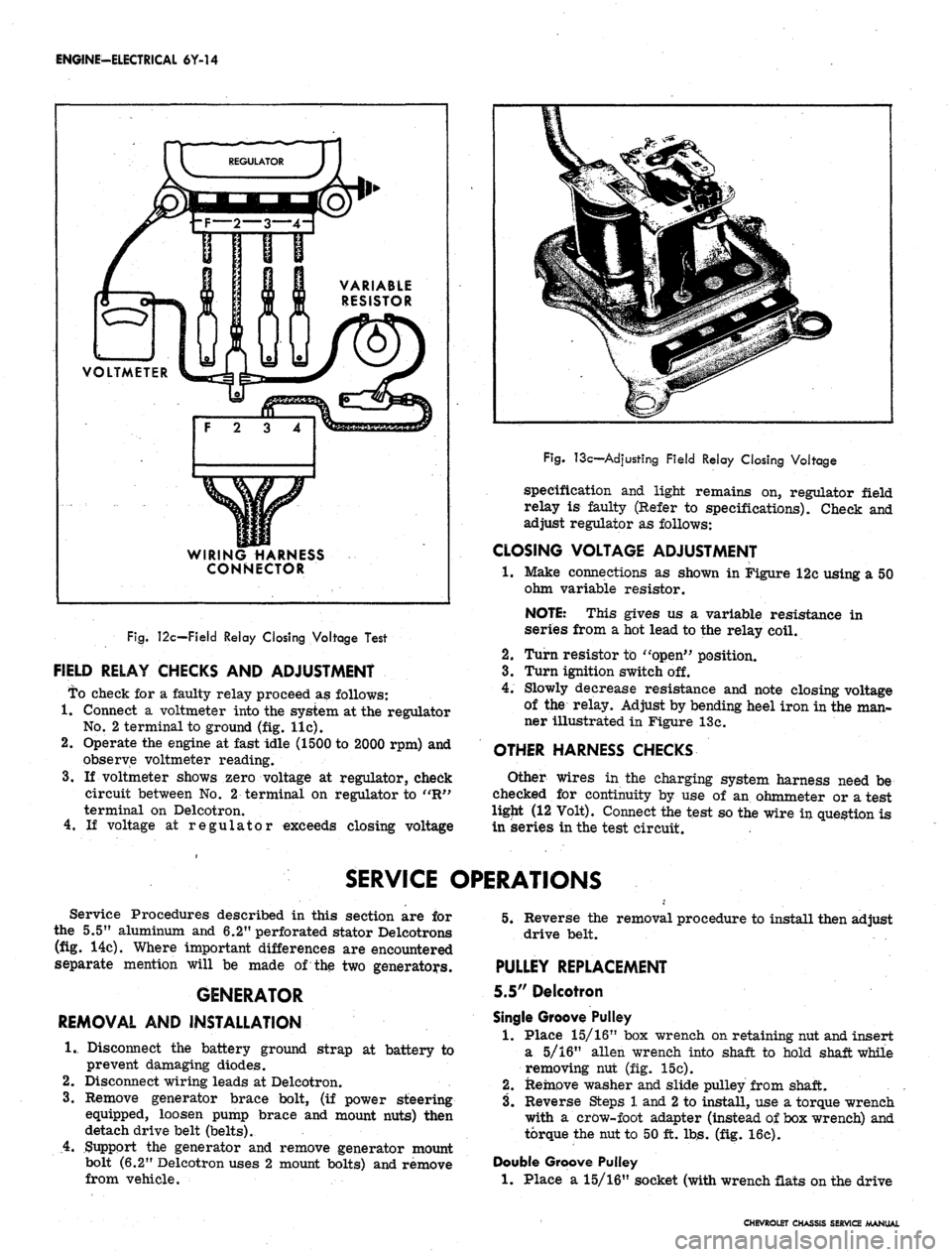
12c—Field Relay Closing Voltage Test
FIELD RELAY CHECKS AND ADJUSTMENT
To check for a faulty relay proceed as follows:
1.
Connect a voltmeter into the system at the regulator
No.
2 terminal to ground (fig. lie).
2.
Operate the engine at fast idle (1500 to 2000 rpm) and
observe voltmeter reading.
3.
If voltmeter shows zero voltage at regulator, check
circuit between No. 2 terminal on regulator to "R"
terminal on Delcotron.
4.
If voltage at regulator exceeds closing voltage
Fig.
13c—Adjusting Field Relay Closing Voltage
specification and light remains on, regulator field
relay is faulty (Refer to specifications). Check and
adjust regulator as follows:
CLOSING VOLTAGE ADJUSTMENT
•1.
Make connections as shown in Figure 12c using a 50
ohm variable resistor.
NOTE: This gives us a variable resistance in
series from a hot lead to the relay coil.
2.
Turn resistor to "open" position.
3.
Turn ignition switch off.
4.
Slowly decrease resistance and note closing voltage
of the relay. Adjust by bending heel iron in the man-
ner illustrated in Figure 13c.
OTHER HARNESS CHECKS
Other wires in the charging system harness need be
checked for continuity by use of an ohmmeter or a test
ligjit (12 Volt). Connect the test so the wire in question is
in series in the test circuit.
SERVICE OPERATIONS
Service Procedures described in this section are for
the 5.5" aluminum and 6.2" perforated stator Delcotrons
(fig. 14c). Where important differences are encountered
separate mention will be made of the two generators.
GENERATOR
REMOVAL AND INSTALLATION
1.
Disconnect the battery ground strap at battery to
prevent damaging diodes.
2.
Disconnect wiring leads at Delcotron.
3.
Remove generator brace bolt, (if power steering
equipped, loosen pump brace and mount nuts) then
detach drive belt (belts).
4.
Support the generator and remove generator mount
bolt (6.2" Delcotron uses 2 mount bolts) and remove
from vehicle.
5.
Reverse the removal procedure to install then adjust
drive belt.
PULLEY REPLACEMENT
5.5" Delcotron
Single Groove Pulley
1.
Place 15/16" box wrench on retaining nut and insert
a 5/16" alien wrench into shaft to hold shaft while
removing nut (fig. 15c).
2.
Remove washer and slide pulley from shaft.
3.
Reverse Steps 1 and
2
to install, use a torque wrench
with a crow-foot adapter (instead of box wrench) and
torque the nut to 50 ft. lbs. (fig. 16c).
Double Groove Pulley
1.
Place a 15/16" socket (with wrench flats on the drive
CHEVROLET CHASSIS SERVICE MANUAL
Page 430 of 659
FUEL TANK
AND
EXHAUST SYSTEMS
8-24
EXHAUST SYSTEMS
INDEX
Page
General Description. ..........
8-24
Service Operations
8-24
Muffler Assembly.
8-24
Side Mounted Exhaust.
. . . 8-25
GENERAL DESCRIPTION
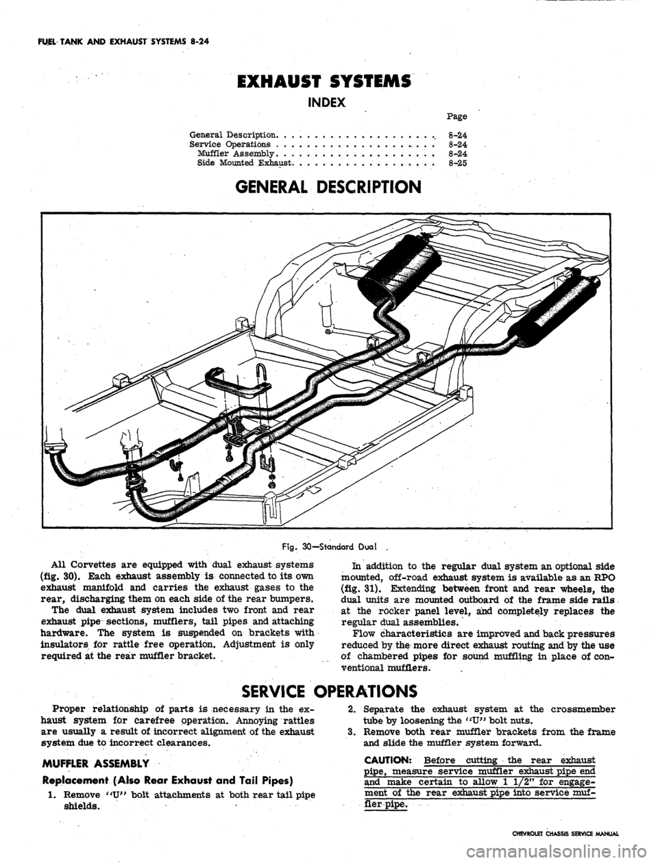
Fig.
30—Standard Dual
All Corvettes
are
equipped with dual exhaust systems
(fig.
30).
Each exhaust assembly
is
connected
to its own
exhaust manifold
and
carries
the
exhaust gases
to the
rear, discharging them
on
each side
of
the rear bumpers.
The dual exhaust system includes
two
front
and
rear
exhaust pipe sections, mufflers, tail pipes and attaching
hardware.
The
system
is
suspended
on
brackets with
insulators
for
rattle free operation. Adjustment
is
only
required
at the
rear muffler bracket.
In addition
to the
regular dual system
an
optional side
mounted, off-road exhaust system
is
available
as an
RPO
(fig.
31).
Extending between front
and
rear wheels,
the
dual units
are
mounted outboard
of the
frame side rails
at
the
rocker panel level,
and
completely replaces
the
regular dual assemblies*
Flow characteristics
are
improved and back pressures
reduced
by
the more direct exhaust routing and
by the use
of chambered pipes
for
sound muffling
in
place
of con-
ventional mufflers.
SERVICE OPERATIONS
Proper relationship
of
parts
is
necessary
in the ex-
haust system
for
carefree operation. Annoying rattles
are usually
a
result
of
incorrect alignment
of
the exhaust
system
due to
incorrect clearances.
MUFFLER ASSEMBLY
Replacement (Also Rear Exhaust
and
Tail Pipes)
Remove
"U"
bolt attachments
at
both rear tail pipe
shields.
2.
crossmember
1.
Separate
the
exhaust system
at the
tube
by
loosening the
"IT"
bolt nuts.
3.
Remove both rear muffler brackets from
the
frame
and slide
the
muffler system forward.
CAUTION: Before cutting
the
rear exhaust
pipe, measure service muffler exhaust pipe
end
and make certain
to
allow
1 1/2" for
engage-
ment
of the
rear exhaust pipe into service
muf-
fler pipe.
CHEVROLET CHASSIS SERVICE MANUAL
Page 514 of 659
ELECTRICAL-BODY AND CHASSIS 12-2
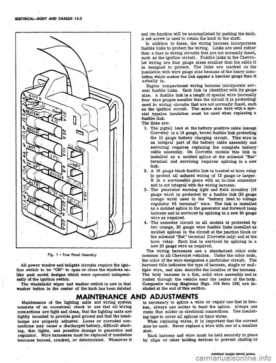
FJg.
1 - Fuse Panel Assembly
All power window and tailgate circuits require the igni-
tion switch to be "ON" to open or close the windows un-
like past model designs which were operated independ-
ently of the ignition switch.
The windshield wiper and washer switch is new in that
washer button in the center of the knob has been deleted
and its function will be accomplished by pushing the knob.
A set screw is used to retain the knob to the shaft.
In addition to fuses, the wiring harness incorporates
fusible links to protect the wiring. Links are used rather
than a fuse in wiring circuits that are not normally fused,
such as the ignition circuit. Fusible links in the Chevro-
let wiring are four gauge sizes smaller than the cable it
is designed to protect. The links are marked on the
insulation with wire gauge size because of the heavy insu-
lation which makes the link appear a heavier gauge than it
actually is.
Engine compartment wiring harness incorporate sev-
eral fusible links. Each link is identified with its gauge
size.
A fusible link is a length of special wire (normally
four wire gauges smaller than the circuit it is protecting)
used in wiring circuits that are not normally fused, such
as the ignition circuit. The same size wire with a spe-
cial hypalon insulation must be used when replacing a
fusible link.
The links are:
1.
The pigtail lead at the battery positive cable (except
Corvette) is a 14 gauge, brown fusible link protecting
the 10 gange battery charging circuit. This wire is
an integral part of the battery cable assembly and
servicing requires replacing the complete battery
cable assembly. On Corvette models this link is
installed as a molded splice at the solenoid "Bat"
terminal and servicing requires splicing in a new
link.
2.
A 16 gauge black fusible link is located at horn relay
to protect all unfused wiring of 12 gauge or larger.
It is a serviceable piece with an in-line connector
and is not integral with the wiring harness.
3.
The generator warning light and field circuitry (16
gauge wire) is protected by a fusible link (20 gauge
orange wire) used in the "battery feed to voltage
regulator #3 terminal" wire. The link is installed
as a molded splice in the generator and forward lamp
harness and is serviced by splicing in a new 20 gauge
wire as required.
4.
The ammeter circuit on all models is protected by
two orange, 20 gauge wire fusible links installed as
molded splices in the circuit at the junction block or
the solenoid "Bat" terminal (Corvette only) and at the
horn relay. Each link is serviced by splicing in a
new 20 gauge wire as required.
The wiring harnesses use a standarized. color code
common to all Chevrolet vehicles. Under the color code,
the color of the wire designates a particular circuit. The
harness title indicates the type of harness, single of mul-
tiple wire, and also describe the location of the harness.
The body harness is a flat, solid wire assembly and is
routed through the vehicle near the center of the body.
Composite wiring diagrams (figs. 104 thru 124) are in-
cluded at the end of this section.
MAINTENANCE AND ADJUSTMENTS
Maintenance of the lighting units and wiring system
consists of an occasional check to see that all wiring
connections are tight and clean, that the lighting units are
tightly mounted to provide good ground and that the head-
lamps are properly adjusted. Loose or corroded con-
nections may cause a discharged battery, difficult start-
ing, dim lights, and possible damage to generator and
regulator. Wire harnesses must be replaced if insulation
becomes burned, cracked, or deteriorated. Whenever it
is necessary to splice a wire or repair one that is bro-
ken, always use solder to bond the splice. Always use
rosin flux solder on electrical connections. Use insulat-
ing tape to cover all splices or bare wires.
When replacing wires, it is important that the correct
size be used. Never replace a wire with one of a smaller
size.
Each harness and wire must be held securely in place
by clips or other holding devices to prevent chafing or
CHEVROLET CHASSIS SERVICE MANUAL
Page 538 of 659
ELECTRICAL-BODY
AND
CHASSIS
12-26
•
Low oil
pressure
• High engine temperature
• Defective wiring
or
switch
connector from sender
in block above starter
on
and
at
left front
of
distributor
on V-8
Sending Unit Replacement
1.
Disconnect wiring harness
unit terminal (located
L-6 engines
engines).
2.
Remove sender unit using Tool J-21757
or 12
point
socket, replace with
new
unit
and
check operation.
GENERATOR INDICATOR
1.
Ignition
on,
Engine
not
Running
and
Telltale Light
Off.
• Indicator bulb burned out, replace bulb.
• Open circuit
or
loose connection
in the
telltale
light circuit.
2.
telltale Light Stays
on
after Engine
is
Started.
If indicator light does
not go out at
engine idle
speed, refer
to
Charging Systems under Engine
Electrical, Section
6Y.
TEMPERATURE (COOLING SYSTEM) INDICATOR
The temperature indicator circuit consists
of two re-
motely located units, indicator gauge
and
engine sender
unit.
The
indicator gauge, located
in the
instrument
panel, consists
of a
red light which will indicate
an
over-
heated engine condition.
Engine Sender Unit Replacement
1.
Drain engine cooling system
to a
level below unit.
2.
Remove sender unit (located
in the
inlet manifold
near water pump housing
on V-8
engines and
in the
cylinder head near
an
exhaust port
oh L-6
engines)
and replace with new unit.
3.
Refill cooling system
and
check operation
of
unit.
CHEVELLE INSTRUMENTS AND GAUGES
INDEX
Page
General Description
* *
i2-26
Service Operations
12-26
Instrument Panel
12-26
Instrument Cluster.
12-26
Fuel Gauge and/or Ammeter
12-27
Clock,
i 12-27
Speedometer
12-27
Page
Speedometer Cable
.
. 12-27
Temperature Gauge
12-29
Oil Pressure Gauge
12-29
Indicator Lights.
. 12-29
Oil Pressure Indicator
12-29
Generator Indicator
. . 12-29
• Temperature Indicator
12-29
GENERAL DESCRIPTION
The Chevelle instrument cluster assembly consists
of:
a speedometer;
a
fuel gauge;
a
generator,
an
engine
tem-
perature and an
oil
pressure indicator lamp, and includes
a clock
on
deluxe models.
On
super sport models,
am-
meter, coolant temperature
and oil
pressure gauges
re-
place
the
appropriate indicator lights. Except
for the
speedometer,
all of the
indicator lamps, instruments
and
gauges
of
these clusters may
be
serviced without remov-
ing
the
instrument cluster assembly from
the
vehicle.
In addition
to the
instrument indicator lamps,
a
brake
warning lamp
is
included
in the
cluster
as
standard
equipment.
The
indicator
is
connected
to the
parking
brake
and
brake pressure differential switches
and
serves
a
dual function.
It
lights when the parking brake
is applied
and
also when
the
brake pedal
is
applied,
if a
malfunction should occur
in the
brake system
due to a
loss
of
hydraulic pressure. Servicing
of the
hydraulic
pressure differential switch
is
covered
in
Section
5 of
this manual.
Regular maintenance
is not
required on the instrument
cjLuster
or its
components other than maintaining dean
and tight electrical connections, replacing defective parts
and keeping
the
speedometer cable properly lubricated.
SERVICE OPERATIONS
INSTRUMENT PANEL ASSEMBLY
INSTRUMENT CLUSTER (Figs.
41
thru
44)
Removal
1.
Disconnect battery ground cable.
2.
Remove steering coupling bolt and disconnect steer-
ing shaft from coupling.
3.
Loosen mast jacket lower clamp.
4.
Remove
air
conditioning center distributor duct
(if
so equipped).
5. Remove radio rear support bracket screw.
6. Remove mast jacket upper support clamp and retain-
ing bolts from lower support (refer
to
Section
9,
Steering).
CAUTION: Cover mast jacket
and
parl
brake handle with
a
suitable material
to
prevc
scratching.
7.
Disconnect speedometer cable
at
rear
of
cluster
housing
and
speed warning control knob
at
panel
(if
so equipped).
8. Remove instrument panel retaining screws (nine
upper and five lower).
.
9. Working under the console remove four lower retain-
ing screws from instrument cluster housing.
10.
Pull instrument panel assembly from console and
lay
forward on mast jacket.
11.
Disconnect wiring harness, cluster lamps and wiring
CHEVROLET CHASSIS SERVICE MANUAL
Page 541 of 659
ELECTRICAL-BODY AND CHASSIS 12-29
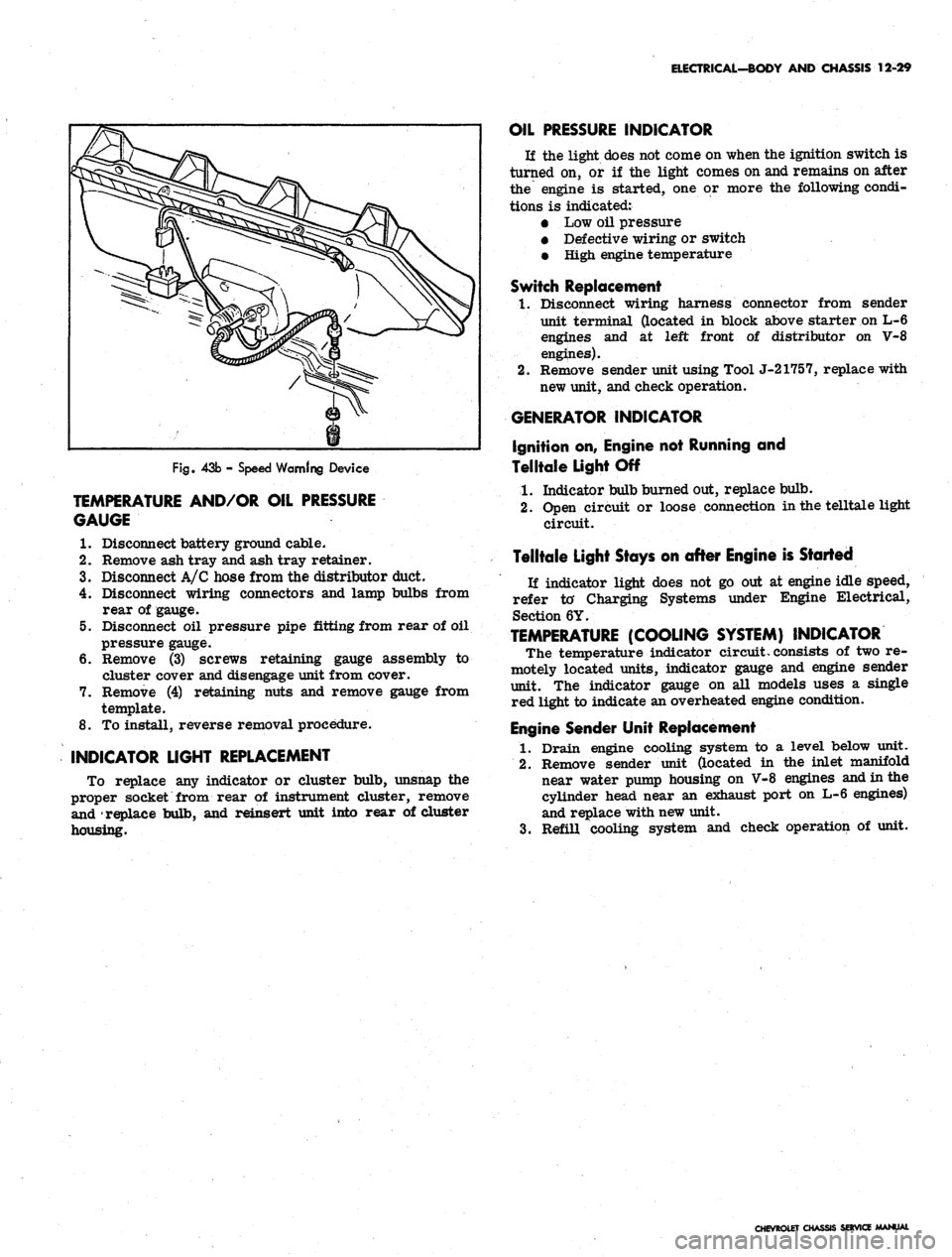
Fig.
43b - Speed Warning Device
TEMPERATURE AND/OR OIL PRESSURE
GAUGE
1.
Disconnect battery ground cable.
2.
Remove ash tray and ash tray retainer.
3.
Disconnect A/C hose from the distributor duct.
4.
Disconnect wiring connectors and lamp bulbs from
rear of gauge.
5. Disconnect oil pressure pipe fitting from rear of oil
pressure gauge.
6. Remove (3) screws retaining gauge assembly to
cluster cover and disengage unit from cover.
7. Remove (4) retaining nuts and remove gauge from
template.
8. To install, reverse removal procedure.
INDICATOR LIGHT REPLACEMENT
To replace any indicator or cluster bulb, unsnap the
proper socket from rear of instrument cluster, remove
and replace bulb, and reinsert unit into rear of cluster
housing.
OIL PRESSURE INDICATOR
If the light does not come on when the ignition switch is
turned on, or if the light comes on and remains on after
the engine is started, one or more the following condi-
tions is indicated:
• Low oil pressure
• Defective wiring or switch
• High engine temperature
Switch Replacement
1.
Disconnect wiring harness connector from sender
unit terminal (located in block above starter on L-6
engines and at left front of distributor on V-8
engines).
2.
Remove sender unit using Tool J-21757, replace with
new unit, and check operation.
GENERATOR INDICATOR
Ignition on, Engine not Running and
Telltale Light Off
1.
Indicator bulb burned out, replace bulb.
2.
Open circuit or loose connection in the telltale light
circuit.
Telltale Light Stays on after Engine is Started
If indicator light does not go out at engine idle speed,
refer to' Charging Systems under Engine Electrical,
Section 6Y.
TEMPERATURE
(COOLING
SYSTEM)
INDICATOR
The temperature indicator circuit, consists of two re-
motely located units, indicator gauge and engine sender
unit. The indicator gauge on all models uses a single
red light to indicate an overheated engine condition.
Engine Sender Unit Replacement
1.
Drain engine cooling system to a level below unit.
2.
Remove sender unit (located in the inlet manifold
near water pump housing on V-8 engines and in the
cylinder head near an exhaust port on L-6 engines)
and replace with new unit.
3.
Refill cooling system and check operation of unit.
CHEVROLET CHASSIS SERVICE MANUAL
Page 546 of 659
ELECTRICAL-BODY AND CHASSIS 12-34
5. To replace, reverse the removal procedure.
SPEEDOMETER REPLACEMENT
1.
Remove instrument cluster as previously described
in this section.
2.
Remove clock set shaft knob.
3.
Remove eight screws securing cluster housing to
bezel trim panel. Separate parts carefully observing
stack up of parts.
4.
Remove two screws securing speedometer head to
rear of cluster housing.
NOTE:
Servicing of the speedometer head
should be performed by an authorized AC Speed-
ometer Service Station.
5. To install, reverse the removal procedure..
SPEEDOMETER CABLE
Replacement or Lubricatibn
1.
Disconnect the speedometer cable from the speed-
ometer head. Remove the old cable by pulling it out
from speedometer end of conduit.
NOTE:
If old cable is broken it may be neces-
sary to remove lower piece from transmission
end of conduit.
2.
Lubricate the lower 3/4 of cable with speedometer
cable lubricant and push the cable into the conduit.
Connect the upper end to the speedometer head and
road test vehicle for proper speedometer operation.
INDICATOR LIGHT REPLACEMENT
To replace any indicator or cluster bulb, unsnap the
proper socket from rear of instrument cluster, remove
and replace bulb, and reinsert unit into rear of cluster
housing.
OIL PRESSURE INDICATOR
If the light does not come on when the ignition switch
is turned on, or if the light comes on and remains on
after the engine is started, one or more of the following
conditions is indicated:
• Low oil pressure
• High engine temperature
• Defective wiring or switch
Switch Replacement
1.
Disconnect wiring harness connector from sender
unit terminal (located in block above starter on
L-6 engines and at left front of distributor on V-8
engines).
2.
Remove sender unit, replace with new unit, and
; check operation.
GENERATOR INDICATOR
1.
Ignition on, engine not running and telltale light off.
a. Indicator bulb burned out, replace bulb.
b.
Open circuit or loose connection in the telltale
light circuit.
2.
Telltale light stays on after engine is started.
a. If indicator light does not go out at engine idle
speed, refer to Charging Systems under Engine
Electrical, Section 6Y.
TEMPERATURE (COOLING SYSTEM) INDICATOR
The temperature indicator circuit consists of two re-
motely located units, indicator gauge and engine sender
unit. The indicator gauge on all models uses a single
red light to indicate an overheated engine condition.
Engine Sender Unit Replacement
1.
Drain engine cooling system to a level below unit.
2.
Remove sender unit (located in the inlet manifold
near water pump housing on V-8 engines and in the
cylinder head near an exhaust port on L-6 engines)
and replace with new unit.
3.
Refill cooling system and check operation of unit.
CORVETTE INSTRUMENTS AND GAUGES
INDEX
Page
General Description ., 12-34
Service Operations . 12-35
Instrument Cluster ., 12-35
Fuel Gauge 12-35
Speedometer/Tachometer Service. 12-35
Temperature Gauge 12-35
Ammeter/Oil Pressure Gauges 12-35
GENERAL DESCRIPTION
All Corvette instruments and gauges are conveniently
located in the dash-mounted cluster. The entire cluster
is removable to permit servicing of the various instru-
ments and gauges. The indicator and cluster illuminating
bulbs may be replaced without removing the cluster from
the panel.
Regular maintenance is not required on the instrument
cluster or its components other than maintaining clean
and keeping the speedometer and tachometer cables
properly lubricated.
CHEVROLET CHASSIS SERVICE MANUAL
Page 550 of 659
ELECTRICAL-BODY AND CHASSIS 12-38
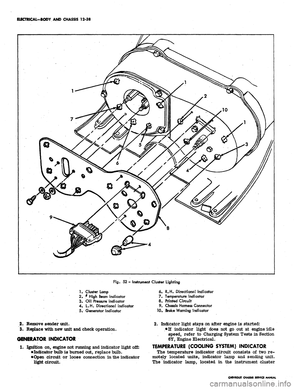
Fig.
52 - Instrument Cluster Lighting
1
• Cluster Lamp
2.
* High Beam Indicator
3. Oil Pressure Indicator
4.
L.H. Directional Indicator
5. Generator indicator
6. R.H. Directional indicator
7. Temperature Indicator
8. Printed Circuit
9. Chassis Harness Connector
10,
Brake Warning Indicator
2.
Remove sender unit.
3.
Replace with new unit and check operation.
GENERATOR INDICATOR
1.
Ignition on, engine not running and indicator light off:
•Indicator bulb is burned out, replace bulb.
•Open circuit or loose connection in the indicator
light circuit.
2.
Indicator light stays on after engine is started:
•Ti indicator light does not go out at engine idle
speed, refer to Charging System Tests in Section
6Y, Engine Electrical.
TEMPERATURE (COOLING SYSTEM) INDICATOR
The temperature indicator circuit consists of two re-
motely located units, indicator lamp and sending unit.
The "indicator lamp, located in the instrument cluster
CHfVROtEr CHASM SfXVICf