fuel pump CHEVROLET CAMARO 1967 1.G Chassis Owner's Manual
[x] Cancel search | Manufacturer: CHEVROLET, Model Year: 1967, Model line: CAMARO, Model: CHEVROLET CAMARO 1967 1.GPages: 659, PDF Size: 114.24 MB
Page 426 of 659
FUEL TANK AND EXHAUST SYSTEMS 8-20
4.
Attach the retaining straps with strap guide attached
to the fuel tank support, and secure with-the nut and
lockwasher assembly.
5. Connect the filler neck boot to the drain hose of the
tank and install boot around filler neck,
6. Connect the fuel pickup line, ground wire and make
certain that the fuel drain line is flush to 1/2" in-
board of the rear bumper opening.
7. Attach tank metering unit wires (fig. 25).
8. Replace fuel in tank. Replace gas cap.
9. Check for possible leaks.
10.
Reconnect the exhaust system by reversing the above
removal procedures (see "Exhaust System").
11.
Install spare tire carrier by securing the bolt
attachment.
12.
Install the spare tire in the tire carrier.
Removal (36 Gallon Tank)
1.
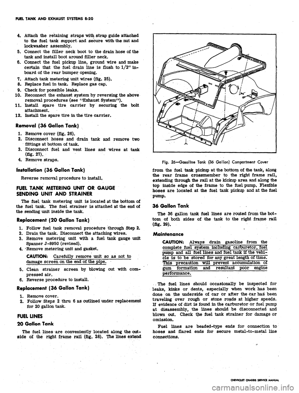
Remove cover (fig. 26).
2.
Disconnect hoses and drain tank and remove two
fittings at bottom of tank.
3.
Disconnect fuel and vent lines and wires at tank
(fig. 27).
4.
Remove straps.
installation (36 Gallon Tank)
Reverse removal procedure to install.
FUEL TANK METERING UNIT OR GAUGE
SENDING UNIT AND STRAINER
The fuel tank metering unit is located at the bottom of
the fuel tank. The fuel strainer is attached at the end of
the sending unit inside the tank.
Replacement (20 Gallon Tank)
1.
Follow fuel tank removal procedure through Step 2.
2.
Drain the tank. Disconnect the attaching wires.
3.
Remove metering unit with a fuel tank gauge unit
Spanner J-8950 (revised).
4.
'Remove metering unit and gasket.
CAUTION: Carefully remove unit so as not to
damage screen on the end of the pipe.
5. Clean strainer screen by blowing out with com-
pressed air.
6. Reverse procedure to install.
Replacement (36 Gallon Tank)
1.
Remove cover.
2.
Follow Steps 2 thru 6 as outlined under replacement
for 20 gallon tank.
FUEL LINES
20 Gallon Tank
The fuel lines are conveniently located along the out-
side of the right frame rail (fig. 28). The lines extend
Fig.
26—Gasoline Tank (36 Gallon) Compartment Cover
from the fuel tank pickup at the bottom of the tank, along
the rear frame crossmember to the right frame rail,
extending through the rail at the kickup area and along the
top inside edge of the frame to the fuel pump, Flexible
hoses are located at the fuel tank pickup and at the fuel
pump.
36 Gallon Tank
The 36 gallon tank fuel lines are routed from the bot-
tom of both sides of the tank to the right frame rail
(fig. 20).
Maintenance
CAUTION: Always drain gasoline from the
complete fuel system including carburetor, fuel
pump and all fuel lines and fuel tank if the vehi-
cle is to be stored for any great length of time.
This precaution will prevent accumulation~ol
gum formation and resultant poor engine
performance.
. The fuel lines should occasionally be inspected for
leaks,
kinks or dents, especially when work has been
done on the underside of car or after the car has been
traveling over rough or stone roads at higher speeds.
If evidence of dirt is found in the carburetor or fuel pump
at disassembly, the lines should be disconnected and
blown put. Check the fuel tank strainer for damage or
omission.
Fuel lines are beaded-type ends for connection to
hoses and flared ends for secure metal-to-metal line
connections.
CHEVROLET CHASSIS SERVICE MANUAL
Page 434 of 659
FUEL TANK AND EXHAUST SYSTEMS 8-28
assembly is mounted on top of the tank and cannot be
removed for service without lowering the tank. The
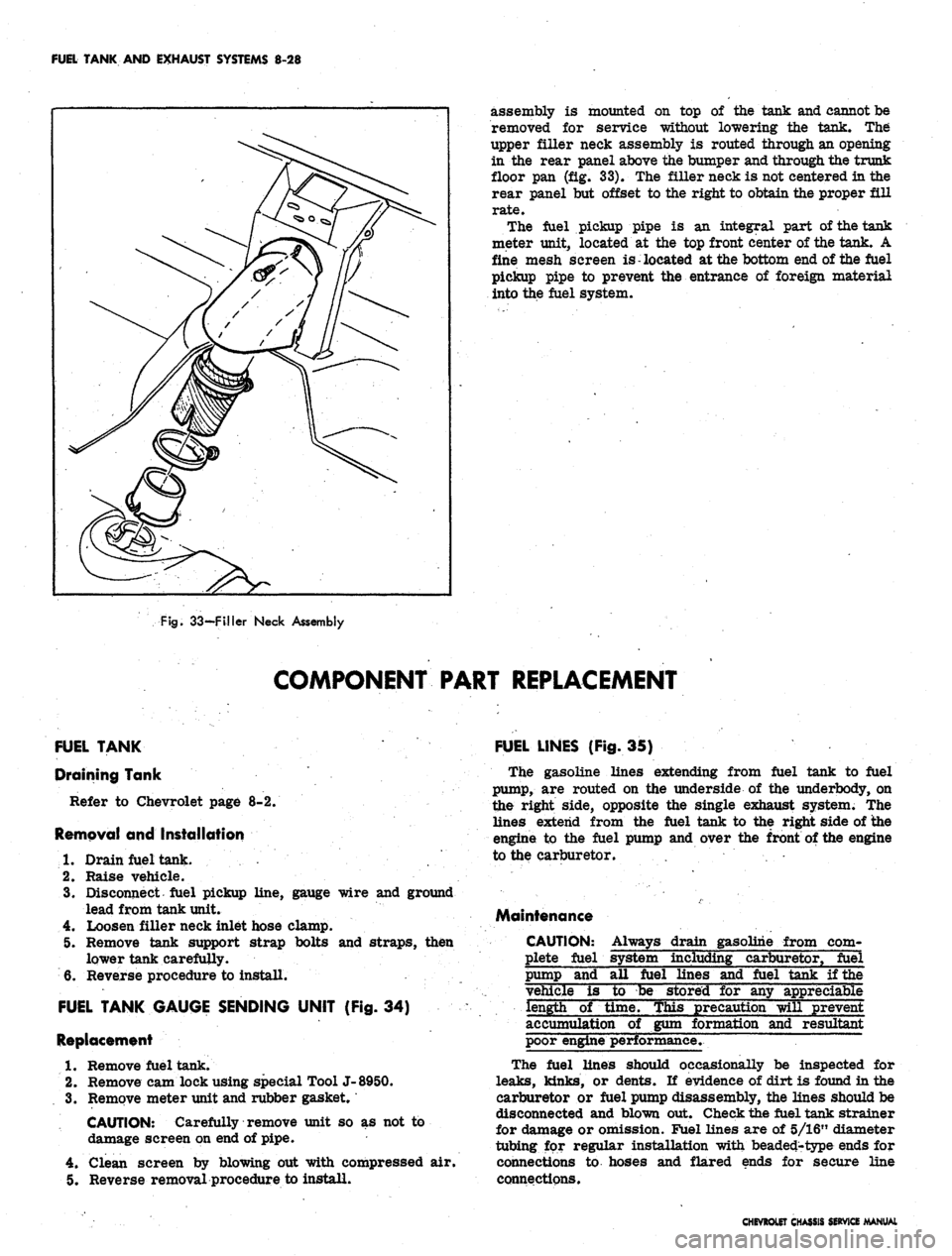
upper filler neck assembly is routed through an opening
in the rear panel above the bumper and through the trunk
floor pan (fig. 33). The filler neck is not centered in the
rear panel but offset to the right to obtain the proper fill
rate.
The fuel pickup pipe is an integral part of the tank
meter unit^ located at the top front center of the tank. A
fine mesh screen is located at the bottom end of the fuel
pickup pipe to prevent the entrance of foreign material
into the fuel system.
Fig.
33—Filler Neck Assembly
COMPONENT PART REPLACEMENT
FUEL TANK
Draining Tank
Refer to Chevrolet page 8-2.
Removal and Installation
1.
Drain fuel tank. .'...' .
2.
Raise vehicle.
3.
Disconnect fuel pickup line, gauge wire and ground
lead from tank unit.
4.
Loosen filler neck inlet hose clamp.
5. Remove tank support strap bolts and straps, then
lower tank carefully.
6. Reverse procedure to install.
FUEL TANK GAUGE SENDING UNIT (Fig. 34)
Replacement
1.
Remove fuel tank.
2.
Remove cam lock using special Tool J-8950.
3.
Remove meter unit and rubber gasket.
CAUTION: Carefully remove unit so as not to
damage screen on end of pipe.
4.
Clean screen by blowing out with compressed air.
5. Reverse removal procedure to install.
FUEL LINES (Fig. 35)
The gasoline lines extending from fuel tank to fuel
pump,
are routed on the underside of the underbody, on
the right side, opposite the single exhaust system. The
lines extend from the fuel tank to the right side of the
engine to the fuel pump and over the front of the engine
to the carburetor.
Maintenance
CAUTION:
plete fuel
Always drain gasoline from corn-
including carburetor, fuel
pump and
fuel lines and fuel tank if the
vehicle is to be stored for any
eciable
length of time. This precaution will prevent
accumulation of gum formation and resultant
poor engine performance.
The fuel lines should occasionally be inspected for
leaks,
kinks, or dents. If evidence of dirt is found in the
carburetor or fuel pump disassembly, the lines should be
disconnected and blown out. Check the fuel tank strainer
for damage or omission. Fuel lines are of 5/16" diameter
tubing for regular installation with beaded-type ends for
connections to hoses and flared ends for secure line
connections.
CHEVROLET CHASSIS SERVICE MANUAL
Page 538 of 659
ELECTRICAL-BODY
AND
CHASSIS
12-26
•
Low oil
pressure
• High engine temperature
• Defective wiring
or
switch
connector from sender
in block above starter
on
and
at
left front
of
distributor
on V-8
Sending Unit Replacement
1.
Disconnect wiring harness
unit terminal (located
L-6 engines
engines).
2.
Remove sender unit using Tool J-21757
or 12
point
socket, replace with
new
unit
and
check operation.
GENERATOR INDICATOR
1.
Ignition
on,
Engine
not
Running
and
Telltale Light
Off.
• Indicator bulb burned out, replace bulb.
• Open circuit
or
loose connection
in the
telltale
light circuit.
2.
telltale Light Stays
on
after Engine
is
Started.
If indicator light does
not go out at
engine idle
speed, refer
to
Charging Systems under Engine
Electrical, Section
6Y.
TEMPERATURE (COOLING SYSTEM) INDICATOR
The temperature indicator circuit consists
of two re-
motely located units, indicator gauge
and
engine sender
unit.
The
indicator gauge, located
in the
instrument
panel, consists
of a
red light which will indicate
an
over-
heated engine condition.
Engine Sender Unit Replacement
1.
Drain engine cooling system
to a
level below unit.
2.
Remove sender unit (located
in the
inlet manifold
near water pump housing
on V-8
engines and
in the
cylinder head near
an
exhaust port
oh L-6
engines)
and replace with new unit.
3.
Refill cooling system
and
check operation
of
unit.
CHEVELLE INSTRUMENTS AND GAUGES
INDEX
Page
General Description
* *
i2-26
Service Operations
12-26
Instrument Panel
12-26
Instrument Cluster.
12-26
Fuel Gauge and/or Ammeter
12-27
Clock,
i 12-27
Speedometer
12-27
Page
Speedometer Cable
.
. 12-27
Temperature Gauge
12-29
Oil Pressure Gauge
12-29
Indicator Lights.
. 12-29
Oil Pressure Indicator
12-29
Generator Indicator
. . 12-29
• Temperature Indicator
12-29
GENERAL DESCRIPTION
The Chevelle instrument cluster assembly consists
of:
a speedometer;
a
fuel gauge;
a
generator,
an
engine
tem-
perature and an
oil
pressure indicator lamp, and includes
a clock
on
deluxe models.
On
super sport models,
am-
meter, coolant temperature
and oil
pressure gauges
re-
place
the
appropriate indicator lights. Except
for the
speedometer,
all of the
indicator lamps, instruments
and
gauges
of
these clusters may
be
serviced without remov-
ing
the
instrument cluster assembly from
the
vehicle.
In addition
to the
instrument indicator lamps,
a
brake
warning lamp
is
included
in the
cluster
as
standard
equipment.
The
indicator
is
connected
to the
parking
brake
and
brake pressure differential switches
and
serves
a
dual function.
It
lights when the parking brake
is applied
and
also when
the
brake pedal
is
applied,
if a
malfunction should occur
in the
brake system
due to a
loss
of
hydraulic pressure. Servicing
of the
hydraulic
pressure differential switch
is
covered
in
Section
5 of
this manual.
Regular maintenance
is not
required on the instrument
cjLuster
or its
components other than maintaining dean
and tight electrical connections, replacing defective parts
and keeping
the
speedometer cable properly lubricated.
SERVICE OPERATIONS
INSTRUMENT PANEL ASSEMBLY
INSTRUMENT CLUSTER (Figs.
41
thru
44)
Removal
1.
Disconnect battery ground cable.
2.
Remove steering coupling bolt and disconnect steer-
ing shaft from coupling.
3.
Loosen mast jacket lower clamp.
4.
Remove
air
conditioning center distributor duct
(if
so equipped).
5. Remove radio rear support bracket screw.
6. Remove mast jacket upper support clamp and retain-
ing bolts from lower support (refer
to
Section
9,
Steering).
CAUTION: Cover mast jacket
and
parl
brake handle with
a
suitable material
to
prevc
scratching.
7.
Disconnect speedometer cable
at
rear
of
cluster
housing
and
speed warning control knob
at
panel
(if
so equipped).
8. Remove instrument panel retaining screws (nine
upper and five lower).
.
9. Working under the console remove four lower retain-
ing screws from instrument cluster housing.
10.
Pull instrument panel assembly from console and
lay
forward on mast jacket.
11.
Disconnect wiring harness, cluster lamps and wiring
CHEVROLET CHASSIS SERVICE MANUAL
Page 546 of 659
ELECTRICAL-BODY AND CHASSIS 12-34
5. To replace, reverse the removal procedure.
SPEEDOMETER REPLACEMENT
1.
Remove instrument cluster as previously described
in this section.
2.
Remove clock set shaft knob.
3.
Remove eight screws securing cluster housing to
bezel trim panel. Separate parts carefully observing
stack up of parts.
4.
Remove two screws securing speedometer head to
rear of cluster housing.
NOTE:
Servicing of the speedometer head
should be performed by an authorized AC Speed-
ometer Service Station.
5. To install, reverse the removal procedure..
SPEEDOMETER CABLE
Replacement or Lubricatibn
1.
Disconnect the speedometer cable from the speed-
ometer head. Remove the old cable by pulling it out
from speedometer end of conduit.
NOTE:
If old cable is broken it may be neces-
sary to remove lower piece from transmission
end of conduit.
2.
Lubricate the lower 3/4 of cable with speedometer
cable lubricant and push the cable into the conduit.
Connect the upper end to the speedometer head and
road test vehicle for proper speedometer operation.
INDICATOR LIGHT REPLACEMENT
To replace any indicator or cluster bulb, unsnap the
proper socket from rear of instrument cluster, remove
and replace bulb, and reinsert unit into rear of cluster
housing.
OIL PRESSURE INDICATOR
If the light does not come on when the ignition switch
is turned on, or if the light comes on and remains on
after the engine is started, one or more of the following
conditions is indicated:
• Low oil pressure
• High engine temperature
• Defective wiring or switch
Switch Replacement
1.
Disconnect wiring harness connector from sender
unit terminal (located in block above starter on
L-6 engines and at left front of distributor on V-8
engines).
2.
Remove sender unit, replace with new unit, and
; check operation.
GENERATOR INDICATOR
1.
Ignition on, engine not running and telltale light off.
a. Indicator bulb burned out, replace bulb.
b.
Open circuit or loose connection in the telltale
light circuit.
2.
Telltale light stays on after engine is started.
a. If indicator light does not go out at engine idle
speed, refer to Charging Systems under Engine
Electrical, Section 6Y.
TEMPERATURE (COOLING SYSTEM) INDICATOR
The temperature indicator circuit consists of two re-
motely located units, indicator gauge and engine sender
unit. The indicator gauge on all models uses a single
red light to indicate an overheated engine condition.
Engine Sender Unit Replacement
1.
Drain engine cooling system to a level below unit.
2.
Remove sender unit (located in the inlet manifold
near water pump housing on V-8 engines and in the
cylinder head near an exhaust port on L-6 engines)
and replace with new unit.
3.
Refill cooling system and check operation of unit.
CORVETTE INSTRUMENTS AND GAUGES
INDEX
Page
General Description ., 12-34
Service Operations . 12-35
Instrument Cluster ., 12-35
Fuel Gauge 12-35
Speedometer/Tachometer Service. 12-35
Temperature Gauge 12-35
Ammeter/Oil Pressure Gauges 12-35
GENERAL DESCRIPTION
All Corvette instruments and gauges are conveniently
located in the dash-mounted cluster. The entire cluster
is removable to permit servicing of the various instru-
ments and gauges. The indicator and cluster illuminating
bulbs may be replaced without removing the cluster from
the panel.
Regular maintenance is not required on the instrument
cluster or its components other than maintaining clean
and keeping the speedometer and tachometer cables
properly lubricated.
CHEVROLET CHASSIS SERVICE MANUAL
Page 639 of 659
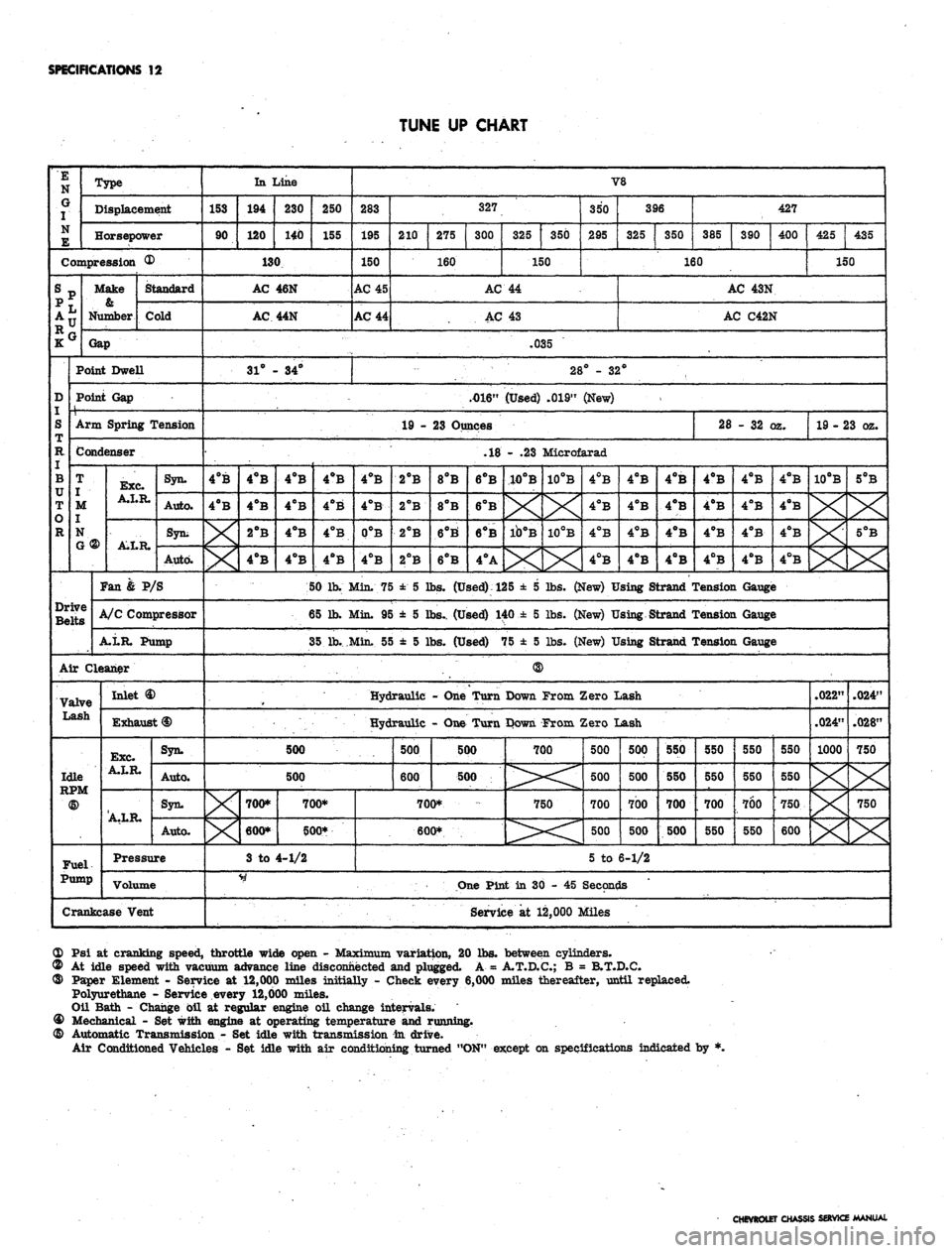
SPECIFICATIONS
12
TUNE UP CHART
E
N
G
I
N
E
Type
Displacement
Horsepower
Compression ®
srp
;•
D
S
R
I
B
TT
T
o
R
Make
0.
Number
Standard
Cold
Gap
Point Dwell
Point Gap
1 ,
Arm Spring Tension
Condenser
T
I
M
j
N
G ®
Drive
Belts
Exc.
A.I.R.
AXR.
Syn.
Auto.
Syn;
Auto.
Fan & P/S
A/C Compressor
A.LR. Pump
Air Cleaner
Valve
Lash
Idle
<§>
Fuel.
Pump
Inlet
Exhaust
<§)
Exc.
A.LR.
A.LR.
Syn.
Auto.
Syn.
Auto.
Pressure
Volume
Crankcase Vent
In Line
153
90
194
120
230
140
250
155
130
AC
AC
31° -
46N
44N
• 34°
V8
283
195
150
AC 45
AC 44
327
210
275
300
160
325
350
150
350
295
396
325
350
427
385
390
400
160
AC 44
AC 43
425
435
150
AC 43N
AC C42N
.035
28° - 32°
.4)16"
(Used) .019" (New)
<
19 - 23 Ounces
4°B
4°B
4°B
4°B
2°B
4°B
4°B
4°B
4°B
4°B
28
- 32 (
yz.
19 - 23 oz.
.18 - .23 Microfarad
4°B
4°B
4°B
4ftB
4°B
4°B
0°B
4°B
50 lb. Min. 75
65 Jh. Min. 95
35 lb..Min. 5£
500
2°B
2°B
2°B
2°B
8PB
8°B
6°B'
6°B
6°B
6°B
6°B
4°A
10°B
X
ib°B
X
10PB
X
10°B
X
4°B
4°B
4°B
4°B
4°B
4°B
4°B
4°B
4°B
4°B
4°B
4°B
± 5 lbs.
(Used):
125 ± 5 lbs. (New) Using Strand '
± 5 lbs.. (Used) 140 ± 5 lbs. (New) Using Strand '
>
± 5 lbs. (Used) 75 ± 5 lbs. (New) Using Strand r
Hydraulic - One Turn Down From Zero Lash
Hydraulic - One Turn Down From Zero Lash
500
X
700*
600*
3 to
700*
500*
4-1/2
500
600
500
500
700*
600*
700
750
500
500
700
500
500
500
700
500
550
550
700
500
4°B
4°B
4°B
4°B
4°B
4°B
4°B
4°B
4°B
4°B
4°B
4°B
Tension Gauge
Tension Gauge
Tension Gauge
550
550
700
550
550
550
700
550
550
550
750
600
10°B
5°B
X
X
.022"
.024"
1000
X
X
X
.024"
.028"
750
X
750
X
5 to 6-1/2
One Pint in 30 - 45 Seconds
Service at 12,000 Miles
OD Psi at cranking speed, throttle wide open - Maximum variation, 20 lbs. between cylinders.
© At idle speed with vacuum advance line disconnected and plugged. A = A.T.D.C.; B = B.T.D.C.
® Paper Element - Service at 12,000 miles initially - Check every 6,000 miles thereafter, until replaced.
Polyurethane - Service every 12,000 miles.
Oil Bath - Change oil at regular engine oil change intervals.
® Mechanical - Set with engine at operating temperature and running.
@ Automatic Transmission - Set idle with transmission in drive.
Air Conditioned Vehicles - Set idle with air conditioning turned "ON" except on specifications indicated by *.
CHEVROLET CHASSIS SERVICE MANUAL