low oil pressure CHEVROLET CAMARO 1967 1.G Chassis Owner's Manual
[x] Cancel search | Manufacturer: CHEVROLET, Model Year: 1967, Model line: CAMARO, Model: CHEVROLET CAMARO 1967 1.GPages: 659, PDF Size: 114.24 MB
Page 223 of 659

REAR SUSPENSION AND DRIVE LINE 4-33
Fig.
84—Drive Pinion Flange Removal
J-21057 for heavy-duty axle, press seal into bore
until it seats against shoulder (figs. 85 and 86).
CAUTION: Pinion oil seal flange must not bot-
tom against "carrier. Press seal into carrier
bore until it seats against internal shoulder -
do not apply unnecessary pressure after seal is
seated. To do so will destroy rubber seat ancl
distort seal. ;
11.
Position and align pinion flange on pinion shaft using
Tools J-9458 and
J-8614-1.
Tool J-9458-1 is
threaded onto pinion shaft and nut tightened against
J-9458-2 to pull flange on shaft (fig. 87). Remove
Fig.
86—Drive Pinion Flange Oil Seal
Installation (Heavy-Duty)
J-9458 after flange is seated.
NOTE: The position of the pinion and flange
was previously marked so that reinstallation
may be made with flange and pinion in same
relative position.
CAUTION: Do not attempt to hammer flange
onto pinion shaft. To do so will damage ring
gear and pinion.
12.
13.
14.
15.
Pack the cavity between end of pinion splines and
pinion flange with a non-hardening sealer (such as
Permatex Type A) prior to installing washer and
nut on pinion.
Install washer and a new self-locking nut on pinion
shaft. Tighten nut to remove end play and continue
alternately tightening in small increments and check-
ing preload with torque wrench until it is the same
as that recorded in Step 4.
Reassemble the rear universal joint, and torque
"V" bolt nuts to specifications.
Lower vehicle to floor and road test for leaks.
Fig.
85—Drive Pinion Flange Oil Seal
Installation (Light-Duty)
Fig.
87—Drive Pinion Flange Installation
CHEVROLET CHASSIS SERVICE MANUAL
Page 236 of 659
BRAKES
5-3
PRIMARY
SHOE
PAWL
WIRE LINK
OVERRIDE
LEVER
VERRIDE
SPRING
RETURN
SPRING
STAR
WHEEL
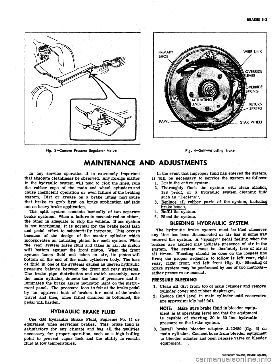
Fig.
3—Camaro
Pressure
Regulator
Valve
Fig.
4-Self-Adjusting
Brake
MAINTENANCE AND ADJUSTMENTS
In any service operation it is extremely important
that absolute cleanliness be observed. Any foreign matter
in the hydraulic system will tend to clog the lines, ruin
the rubber cups of the main and wheel cylinders and
cause inefficient operation or even failure of the braking
system. Dirt or grease on a brake lining may cause
that brake to grab first on brake application and fade
out on heavy brake application.
The split system consists basically of two separate
brake systems. When a failure is encountered on either,
the other is adequate to stop the vehicle. If one system
is not functioning, it is normal for the brake pedal lash
and pedal effort to substantially increase. This occurs
because of the design of the master cylinder which
incorporates ah actuating piston for each system. When
the rear system loses fluid and takes in air, its piston
will bottom against the front piston. When the front
system loses fluid and takes in air, its piston will
bottom on the end of the main cylinders body. The loss
of fluid in one of the systems causes an uneven hydraulic
pressure balance between the front and rear systems.
The brake pipe distribution and switch assembly, near
the main cylinder, detects the loss of pressure and il-
luminates the brake alarm indicator light on the instru-
ment panel. The pressure loss is felt at the brake pedal
by an apparent lack of brakes for most of the brake
travel and then, when failed chamber is bottomed, the
pedal will harden.
HYDRAULIC BRAKE FLUID
Use GM Hydraulic Brake Fluid, Supreme No. 11 or
equivalent when servicing brakes. This brake fluid is
satisfactory for any climate and has all the qualities
necessary for proper operation, such as a high boiling
point to prevent vapor lock and the ability to remain
fluid at low temperatures.
In the event that improper fluid has entered the system,
it will be necessary to service the system as follows:
1.
Drain the entire system.
2.
Thoroughly flush the system with clean alcohol,
188
proof,
or a hydraulic system cleaning fluid
such as "Declene".
3.
Replace all rubber parts of the system, including
brake hoses.
4.
Refill the system.
5. Bleed the system.
BLEEDING HYDRAULIC SYSTEM
The hydraulic brake system must be bled whenever
any line has been disconnected or air has in some way
entered the system. A ''spongy" pedal feeling when the
brakes are applied may indicate presence of air in the
system. The system must be absolutely free of air at
all times. Bleeding should be done on the longest line
first; the proper sequence to follow is left rear, right
rear, right front, and left front (fig. 5). Bleeding of
brake system may be performed by one of two methods—
either pressure or manual.
PRESSURE
BLEEDING
1.
Clean all dirt from top of main cylinder and remove
cylinder cover and rubber diaphragm.
2.
Reduce fluid level in main cylinder until reservoirs
are approximately half full.
NOTE:
Make sure brake fluid in bleeder equip-
ment is at operating level and that the. equipment
is capable of exerting 30 to 50 lbs. hydraulic
pressure on the brake system.
3.
Install brake bleeder adapter J-22489 (fig. 6) on
main cylinder. Connect hose from bleeder equipment
to bleeder adapter and open release valve on bleeder
equipment.
CHEVROLET CHASSIS SERVICE MANUAL
Page 250 of 659
BRAKES 5-17
mended shoe and lining assemblies. Otherwise,
serious fade or failure may occur.
1.
Inspect new linings and make certain there are no
nicks or burrs on bonding material on shoe edge
where contact is made with brake flange plate or
on any of the contact surfaces.
NOTE: Keep hands clean while handling brake
shoes.
Do not permit oil or grease to come in
contact with linings.
2.
If working on rear brakes, lubricate parking brake
cable.
3.
On rear brakes only, lubricate fulcrum end of park-
ing brake lever and the bolt with brake lube, then
attach lever to secondary shoe with bolt, spring
washer, lock washer and nut. Make sure that lever
moves freely.
4.
Before installation make certain the adjusting screw
is clean and lubricated properly.
NOTE: Loose adjustment may occur from an
adjusting screw that is not properly operating.
If the lubrication in the adjusting screw as-
sembly is contaminated or destroyed, the ad-
justing screw should be thoroughly cleaned and
lubricated.
5.
Connect brake shoes together with adjusting screw
spring, then place adjusting screw, socket and nut
in position.
CAUTION: Make sure the proper adjusting
screw is used ("L" for left side of vehicle,
"R"
for right side of vehicle). The star wheel
should only be installed with the star wheel
nearest to the secondary shoe and the adjusting
screw spring inserted to prevent interference
with the star wheel.
6. On rear wheels connect parking brake cable to lever.
7.
Secure the primary brake shoe (short lining—faces
forward) first with the hold-down pin and spring
using a pair of pliers. Engages shoes with the wheel
cylinder connecting links.
8. Install and secure the actuator assembly and second-
ary brake shoe with the hold-down pin and spring
using a pair of needle nose pliers. On rear wheels
position parking brake strut and strut spring.
9. Install guide plate over anchor pin.
10.
Install the wire link.
NOTE: Do not hook the wire link over the
anchor pin stud with the regular spring hook
tool. This may damage the cylinder boot seals.
Fasten the wire link to the actuator assembly ;
first, then place over the anchor pin stud by
hand while holding the adjuster assembly in the
full down position.
11.
Install actuator return spring.
NOTE: Do not pry actuator lever to install re-
turn spring. Ease it in place using the end of a
screw driver or other suitable flat tool.
12.
If old brake pull back (return) springs are nicked,
distorted or if strength is doubtful, install new
springs.
13.
Hook springs in shoes using Tool J-8049 by in-
stalling the primary spring from the shoe over the
anchor pin and then spring from secondary shoe
over the wire link end.
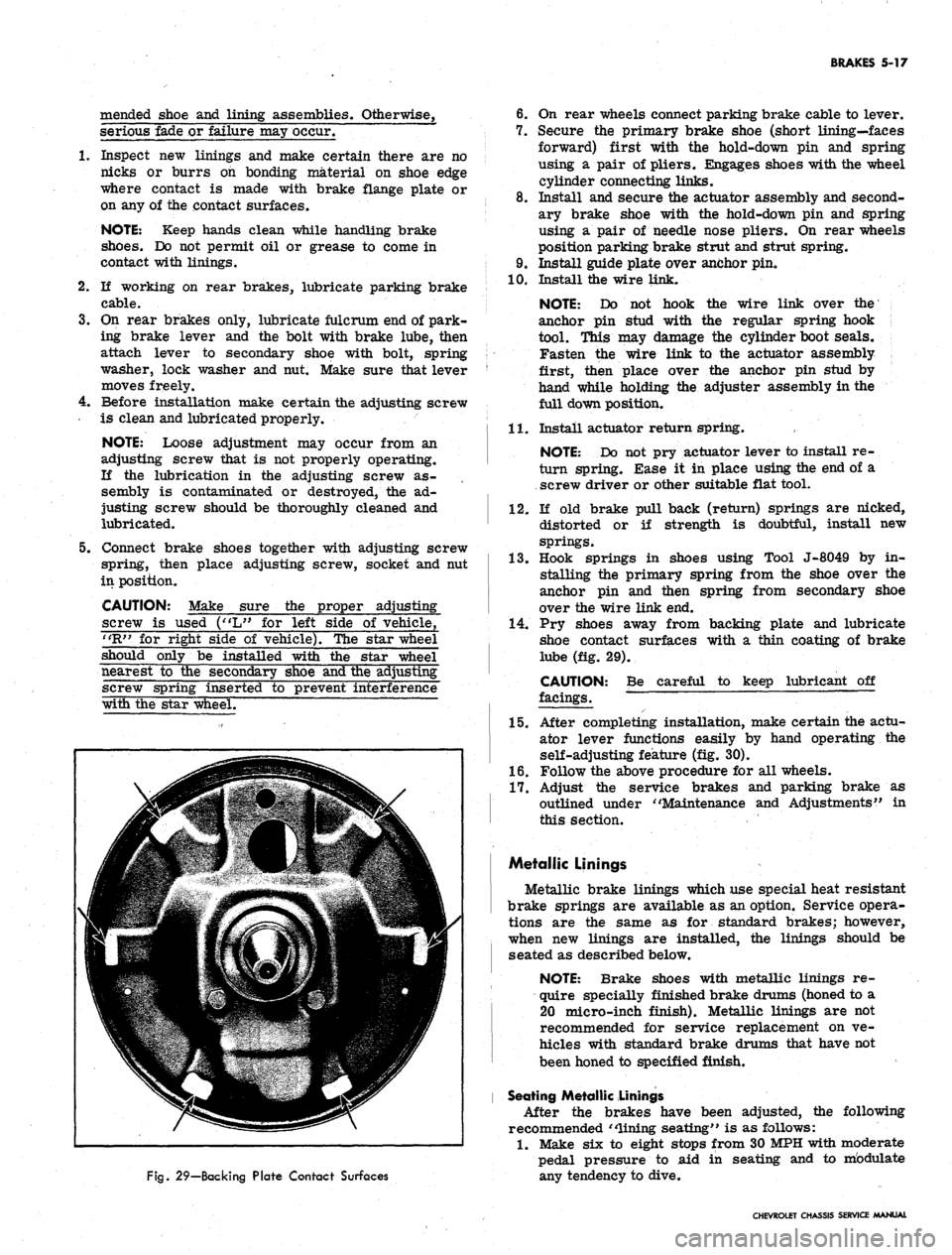
14.
Pry shoes away from backing plate and lubricate
shoe contact surfaces with a thin coating of brake
lube (fig. 29).
CAUTION:
facings.
Be careful to keep lubricant off
Fig.
29—Backing Plate Contact Surfaces
15.
After completing installation, make certain the actu-
ator lever functions easily by hand operating the
self-adjusting feature (fig. 30).
1.6. Follow the above procedure for all wheels.
17.
Adjust the service brakes and parking brake as
outlined under "Maintenance and Adjustments" in
this section.
Metallic Linings
Metallic brake linings which use special heat resistant
brake springs are available as an option. Service opera-
tions are the same as for standard brakes; however,
when new linings are installed, the linings should be
seated as described below.
NOTE: Brake shoes with metallic linings re-
quire specially finished brake drums (honed to a
20 micro-inch finish). Metallic linings are not
recommended for service replacement on ve-
hicles with standard brake drums that have not
been honed to specified finish.
Seating Metallic Linings
After the brakes have been adjusted, the following
recommended "lining seating" is as follows:
1.
Make six to eight stops from 30 MPH with moderate
pedal pressure to aid in seating and to mbdulate
any tendency to dive.
CHEVROLET CHASSIS SERVICE MANUAL
Page 276 of 659
ENGINE 6-11
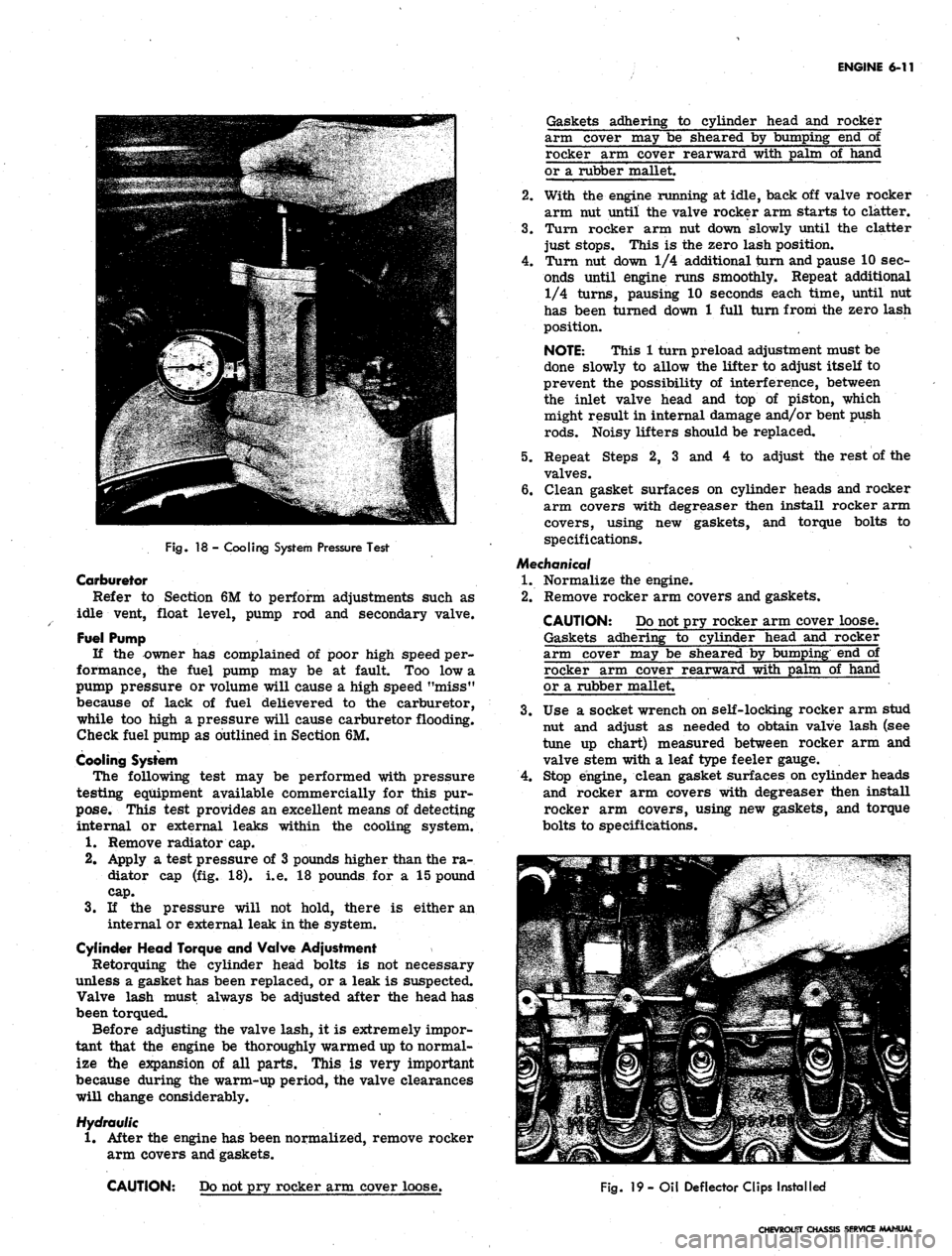
Fig.
18 - Cooling System Pressure Test
Carburetor
Refer to Section 6M to perform adjustments such as
idle vent, float level, pump rod and secondary valve.
Fuel Pump
If the owner has complained of poor high speed per-
formance, the fuel pump may be at fault. Too low a
pump pressure or volume will cause a high speed "miss"
because of lack of fuel delievered to the carburetor,
while too high a pressure will cause carburetor flooding.
Check fuel pump as outlined in Section 6M.
Cooling System
The following test may be performed with pressure
testing equipment available commercially for this pur-
pose.
This test provides an excellent means of detecting
internal or external leaks within the cooling system.
1.
Remove radiator cap.
2.
Apply a test pressure of 3 pounds higher than the ra-
diator cap (fig. 18). i.e. 18 pounds for a 15 pound
cap.
3.
If the pressure will not hold, there is either an
internal or external leak in the system.
Cylinder Head Torque and Valve Adjustment
Retorquing the cylinder head bolts is not necessary
unless a gasket has been replaced, or a leak is suspected.
Valve lash must always be adjusted after the head has
been torqued.
Before adjusting the valve lash, it is extremely impor-
tant that the engine be thoroughly warmed up to normal-
ize the expansion of all parts. This is very important
because during the warm-up period, the valve clearances
will change considerably.
Hydraulic
1.
After the engine has been normalized, remove rocker
arm covers and gaskets.
CAUTION: Do not pry rocker arm cover loose.
Gaskets adhering to cylinder head and rocker
arm cover may be sheared by bumping end of
rocker arm cover rearward with palm of hand
or a rubber mallet.
2.
With the engine running at idle, back off valve rocker
arm nut until the valve rocker arm starts to clatter.
3.
Turn rocker arm nut down slowly until the clatter
just stops. This is the zero lash position.
4.
Turn nut down 1/4 additional turn and pause 10 sec-
onds until engine runs smoothly* Repeat additional
1/4 turns, pausing 10 seconds each time, until nut
has been turned down 1 full turn from the zero lash
position.
NOTE: This 1 turn preload adjustment must be
done slowly to allow the lifter to adjust itself to
prevent the possibility of interference, between
the inlet valve head and top of piston, which
might result in internal damage and/or bent push
rods.
Noisy lifters should be replaced.
5.
Repeat Steps 2, 3 and 4 to adjust the rest of the
valves.
6. Clean gasket surfaces on cylinder heads and rocker
arm covers with degreaser then install rocker arm
covers, using new gaskets, and torque bolts to
specifications.
Mechanical
1.
Normalize the engine.
2.
Remove rocker arm covers and gaskets.
CAUTION: Do not pry rocker arm cover loose.
Gaskets adhering to cylinder head and rocker
arm cover may be sheared by bumping end of
rocker arm cover rearward with palm of hand
or a rubber mallet.
3.
Use a socket wrench on self-locking rocker arm stud
nut and adjust as needed to obtain valve lash (see
tune up chart) measured between rocker arm and
valve stem with a leaf type feeler gauge.
4.
Stop engine, clean gasket surfaces on cylinder heads
and rocker arm covers with degreaser then install
rocker arm covers, using new gaskets, and torque
bolts to specifications.
Fig.
19
- Oil Deflector Clips Installed
CHEVROLET CHASSIS SERVICE MANUAL
Page 279 of 659
ENGINE 6-14
b.
Bolt transmission to engine, then raise engine and
transmission assembly and install flywheel to
converter attaching bolts.
c. Install converter
housing*
underpan and starter.
3.
Tilt and lower engine and transmission assembly into
the chassis as a unit, guiding engine to align front
mounts with frame supports.
4.
Install front mount through bolts and torque to
specifications.
5.
Raise engine enough to install rear crossmember,
then install crossmember, install rear mount, lower
engine and torque bolts to specifications.
6. Remove lifting device and lifting adapter then install
rocker arm cover as outlined.
7.
On synchromesh equipped vehicles, install clutch
cross shaft engine bracket, then adjust and connect
clutch as outlined in Section 7.
8. Connect:
• Speedometer cable.
• Shift linkage at transmission.
9; Install propeller shaft.
10.
Remove jack stands and lower vehicle.
11.
Connect:
Power steering pump lines (if disconnected).
Vacuum line to power brake unit (if disconnected).
Fuel line at fuel pump.
Exhaust pipe at manifold flange.
Accelerator linkage at manifold bellcrank.
12.
Connect wires at:
Coil
Oil pressure switch
Temperature switch
Delcotron
Starter solenoid
13.
Install pulley, fan blade and fan belt as outlined in
Section 6K.
14.
Install radiator and shroud as outlined in Section 13.
15.
Install and adjust hood as outlined in Section 11.
16.
Connect battery cables.
17.
Fill with coolant, engine oil and transmission oil,
then start engine and check for leaks.
18.
Perform necessary adjustments and install air
cleaner.
MANIFOLD ASSEMBLY
Removal
1.
Remove air cleaner.
2.
Disconnect both throttle rods at bellcrank and re-
move throttle return spring.
3.
Disconnect fuel and vacuum lines at carburetor.
Disconnect choke cable on \A engines.
4.
Disconnect crankcase ventilation hose at rocker arm
cover.
5.
Disconnect exhaust pipe at manifold flange and dis-
card packing.
6. Remove manifold attaching bolts and clamps then
remove manifold assembly and discard gaskets.
7.
Check for cracks in manifold castings.
8. If necessary to replace either intake or exhaust
manifolds, separate them by removing one bolt and
two nuts at center of assembly. Reassemble mani-
folds using a new gasket. Tighten finger tight and
torque to specifications after assembly to cylinder
head. Transfer all necessary parts.
Installation
1.
Clean gasket surfaces on cylinder head and
manifolds*
2.
Position new gasket over manifold end studs on head
and carefully install the manifold in position making
sure the gaskets are in place.
3.
Install bolts and clamps while holding manifold in
place with hand.
4.
Torque bolts to specifications.
NOTE: On L6 engines center bolt and end bolt
torque differ.
5.
Connect exhaust pipe to manifold using a new
packing.
6. Connect crankcase ventilation hose at rocker arm
cover.
7.
Connect fuel and vacuum lines at carburetor.
8. On L4 engines connect choke cable and adjust as out-
lines in Section 6M.
9. Connect throttle rods at bellcrank and install throttle
return spring.
10.
Install air cleaner, start engine, check for leaks and
adjust carburetor idle speed and mixture.
ROCKER ARM COVER
Removal
1.
Disconnect crankcase ventilation hose(s) at rocker
arm cover.
2.
Remove air cleaner.
3.
Disconnect temperature wire from rocker arm cover
clips.
4.
Remove rocker arm cover. '
CAUTION: Do Not pry rocker arm cover loose
Gaskets adhering to cylinder head and rocker
arm cover may be sheared by bumping end of
rocker arm cover rearward with palm of hand or
a rubber mallet.
Installation
1.
Clean gasket surfaces on cylinder head and rocker
arm cover with degreaser then, using anew gasket,
install rocker arm cover and torque bolts to
specifications.
2.
Connect temperature wire at rocker arm cover clips.
3.
Install air cleaner.
4.
Connect crankcase ventilation hoses.
VALVE MECHANISM
Removal
1.
Remove rocker arm cover as outlined.
2.
Remove rocker arm nuts, rocker arm
balls,
rocker
arms and push rods.
NOTE:
Place rocker arms, rocker arm balls
and push rods in a rack so they may be rein-
stalled in the same location.
Installation and Adjustment
NOTE:
Whenever new rocker arms and/or
rocker arm balls are being installed, coat bear-
ing surfaces of rocker arms and rocker arm
balls with Molykote or its equivalent.
1.
Install push rods,
socket.
Be sure push rods seat in lifter
CHEVROLET CHASSIS SERVICE MANUAL
Page 284 of 659
ENGINE 6-19
OIL SEAL (REAR MAIN)
Replacement
The rear main bearing oil seal can be replaced (both
halves) without removal of the crankshaft.
NOTE:
Always replace the upper and lower
seal as a unit. Install with the lip facing toward
the front of the engine.
1.
With the oil pan removed, remove the rear main
bearing cap.
2.
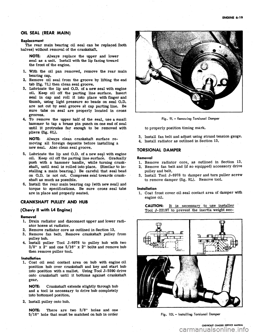
Remove oil seal from the groove by lifting the end
tab (fig. 7L) then clean seal groove.
3.
Lubricate the lip and O.D. of a new seal with engine
oil. Keep oil off the parting line surface. Insert
seal in cap and roll it into place with finger and
thumb,
using light pressure so beads on seal O.D.
are not cut by seal groove at cap parting line. Be
sure tabs on seal are properly located in cross
grooves.
4.
To remove the upper half of the seal, use a small
hammer to tap a brass pin punch on one end of seal
until it protrudes far enough to be removed with
pliers (fig. 8L).
NOTE:
Always clean crankshaft surface re-
moving all foreign deposits before installing a
new seal. Also clean seal groove.
5. Lubricate the lip and O.D. of a new seal with engine
oil. Keep oil off the parting line surface. Gradually
push with a hammer handle, while turning crank-
shaft, until seal is rolled into place. (Similar to in-
stalling a main bearing.) Be careful that seal bead
on O.D. is not cut. Compress seal towards crank-
shaft as much as possible.
6. Install the rear main bearing cap (with new seal) and
torque to specifications. Be sure cross seal tabs
are in place and properly seated.
CRANKSHAFT PULLEY AND HUB
(Chevy II with L4 Engine)
Removal
1.
Drain radiator and disconnect upper and lower radi-
ator hoses at radiator.
2.
Remove radiator core as outlined in Section 13.
3.
Remove fan belt. Remove crankshaft pulley from
pulley hub.
4.
Install puller Tool J-6978 to pulley hub with two
3/8"
x 2" and one 5/16" x 2" bolts and remove hub
then remove puller tool.
Installation
1.
Coat oil seal contact area on hub with engine oil
position hub over crankshaft and key and start hub
into position with a mallet. Using Tool J-5590 drive
onto crankshaft until it bottoms against crankshaft
gear.
NOTE:
Crankshaft extends slightly through hub
and a tool is necessary to drive hub completely
into bottomed position.
2.
Install pulley onto hub.
NOTE:
There are two 3/8" holes and one
5/16" hole that must be matched on hub in order
Fig.
9L - Removing Torsional Damper
to properly position timing mark.
3.
Install fan belt and adjust using strand tension gauge.
4.
Install radiator as outlined in Section 13.
TORSIONAL DAMPER
Removal
1.
Remove radiator core, as outlined in Section 13.
2.
Remove fan belt and (if so equipped) accessory drive
pulley and belt.
3.
Install Tool J-6978 to damper and turn puller screw
to remove damper (fig. 9L). Remove tool.
Installation
1.
Coat front cover oil seal contact area of damper with
engine oil.
CAUTION: It is necessary to use installer
Tool J-22197 to prevent the inertia weight sec-
Fig.
10L - Installing Torsional Damper
CHEVROLET CHASSIS SERVICE MANUAL
Page 290 of 659
ENGINE 6-25
refer to Section 6 of the Chassis Overhaul Manual.
Because of the interchangeability and similarity of
many engines, engine sub-assemblies and engine parts,
regardless of which passenger vehicle they are used in,
typical illustrations and procedures are used except
where specific illustrations or procedures are necessary
to clarify the operation. Although illustrations showing
bench operations are used, most single operations, when
not part of a general overhaul, should be performed (if
practical) with the engine in the vehicle.
COMPONENT REPLACEMENT AND ADJUSTMENT
ENGINE ASSEMBLY
Removal
• .1. Drain cooling system and engine oil.
2.
Remove air cleaner and disconnect battery cables at
battery.
3.
Remove hood as outlined in Section 11.
4.
Remove radiator and shroud as outlined in Sec-
tion 13.
5. Remove fan blade and pulley as outlined in Sec-
tion 6K.
6. Disconnect wires at:
• Starter solenoid
• Delcotron
• Temperature switch
• Oil pressure switch
• Coil
7. Disconnect:
• Accelerator linkage at pedal lever.
• Exhaust pipes at manifold flanges.
• Vacuum line to power brake unit at manifold (if
so equipped),
• Power steering pump lines at pump end (if so
equipped).
• Fuel line (from tank) at fuel pump.
• Engine cooler lines (if so equipped).
• Oil pressure gauge line (if so equipped).
8. Raise vehicle and place on jack stands.
9. Remove propeller shaft.
NOTE:
If plug for propeller shaft opening
in transmission is not available, drain
transmission.
10.
Disconnect:
• Shift linkage at transmission.
• Speedometer cable at transmission.
• Transmission cooler lines (if so equipped).
11.
On synchromesh equipped vehicles, disconnect clutch
linkage at cross-shaft then remove cross-shaft en-
gine bracket.
12.
Remove rocker arm covers as outlined, then attach
engine lifting adapter at the proper cylinder head bolt
locations.
13.
Remove front mount bolts.
14.
Attach lifting device and raise engine to take weight
off front mounts, then remove rear mount bolts.
15.
Raise engine to take weight off rear mount, then re-
move crossmember.
NOTE:
On Chevrolets it will be necessary to
remove mount from transmission before cross-
member can be removed.
16.
Remove engine-transmission assembly from vehicle
as a unit.
17.
Remove transmission (and clutch):
Synchromesh Transmission
a. Remove clutch housing cover plate screws.
b.
Remove bolts attaching the clutch housing to en-
gine block then remove transmission and clutch
housing as a unit.
NOTE:
Support the transmission as the last
mounting bolt is removed, and as it is being
pulled away from the engine (to prevent damage
to clutch disc).
c. Remove starter and clutch housing rear cover
plate.
d. Loosen clutch mounting bolts a turn at a time (to
prevent distortion of clutch cover) until the spring
pressure is released. Remove all bolts, clutch
disc and pressure plate assembly.
Automatic
Transmission
a. Lower engine, secured by the hoist, and support
engine on blocks.
b.
Remove starter and converter housing underpan.
c. Remove flywheel-to-converter attaching bolts.
d. Support transmission on blocks.
e. Remove transmission-to-engine mounting bolts.
f. With the hoist attached, remove blocks from the
engine only and slowly guide the engine from the
transmission.
18.
Mount engine in stand.
Installation
1.
Attach lifting device to engine and remove engine
from engine stand.
2.
Install transmission (and clutch):
Synchromesh Transmission
a. Install the clutch on flywheel as outlined in Sec-
tion 7.
b.
Install clutch housing rear cover and starter.
c. Install transmission and clutch housing as out-
lined in Section 7.
d. Install clutch housing cover screws and tighten
securely.
Automatic
Transmissions
a. Position engine adjacent to the transmission and
align the converter with the flywheel.
b.
Bolt transmission to engine, then raise engine and
transmission assembly and install flywheel to
converter attaching bolts.
c. Install converter housing underpan and starter.
3.
Tilt and lower engine and transmission assembly into
the chassis as a unit, guiding engine to align front
mounts with frame supports.
4.
Install front mount bolts and torque to specifications.
5. Raise engine enough to install rear crossmember,
then install crossmember, install rear mount, lower
engine and torque rear mount to specifications.
CHEVROLET CHASSIS SERVICE MANUAL
Page 291 of 659
ENGINE 6-26
6. Remove lifting device and lifting adapter then install
rocker arm covers as outlined.
7.
On synchromesh equipped vehicles, install clutch
cross-shaft engine bracket, then adjust and connect
clutch as outlined in Section 7.
8. Connect:
• Speedometer cable.
• Shift linkage at transmission.
• Transmission cooler lines (if so equipped).
9. Install propeller shaft.
10.
Remove jack stands and lower vehicle.
11.
Connect: \ '
Power steering pump lines (if so equipped).
Vacuum line to power brake unit (if so equipped).
Exhaust pipes at manifold flanges.
Accelerator linkage at pedal lever.
Fuel line at fuel pump.
Engine cooler lines (if so equipped).
Oil pressure gauge lines (if so equipped).
12.
Connect wires at:
Coil
Oil pressure switch
Temperature switch
Delcotron
Starter solenoid
13.
Install pulley, fan blade and fan belt as outlined in
Section 6K.
14.
Install radiator and shroud as outlined in Section 13.
15.
Install and adjust hood as outlined in Section 11.
16.
Connect battery cables.
17.
Fill with coolant, engine oil and transmission oil,
then start engine and check for leaks.
18.
Perform necessary adjustments and install air
cleaner.
INTAKE MANIFOLD
Removal
1.
Drain radiator and remove air cleaner.
2.
Disconnect:
Battery cables at battery.
Upper radiator and heater hose at manifold.
Accelerator linkage at pedal lever.
Fuel line at carburetor. ;
Wires at temperature sending switch and coil
(both sides).
Power brake hose at carburetor base.
Spark advance hose at distributor.
Crankcase ventilation hoses (as required).
3.
Remove distributor cap and mark rotor position with
chalk. Remove distributor clamp and distributor,
then position distributor cap rearward clear of
manifold.
4.
Remove coil.
5.
Remove manifold-to-head attaching bolts, then re^
move manifold, (with carburetor on) from engine and
discard gaskets and seals.
6. If manifold is to be replaced,,transfer:
Carburetor and carburetor mounting studs.
Temperature sending switch.
Water outlet and thermostat (use new gasket).
Heater hose adapter.
Choke coil.
Installation
1.
Clean gasket and seal surfaces of manifold, cylinder
heads and block.
2.
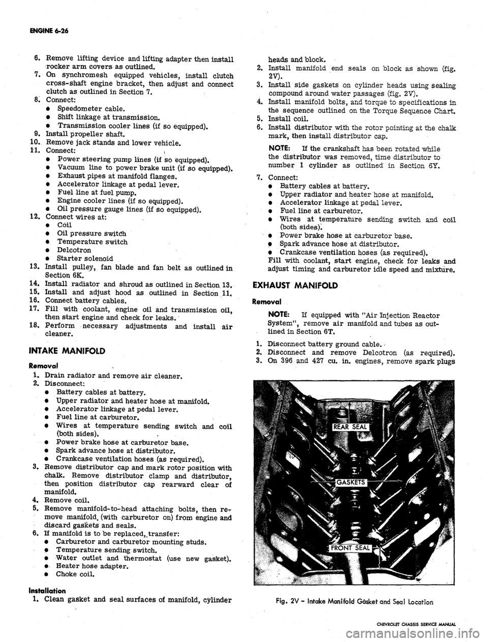
Install manifold end seals on block as shown (fig.
2V).
3.
Install side gaskets on cylinder heads using sealing
compound around water passages (fig. 2V).
4.
Install manifold bolts, and torque to specifications in
the sequence outlined on the Torque Sequence Chart.
5.
Install coil.
6. Install distributor with the rotor pointing at the chalk
mark, then install distributor cap.
NOTE:
If the crankshaft has been rotated while
the distributor was removed, time distributor to
number 1 cylinder as outlined in Section 6Y.
7.
Connect:
Battery cables at battery.
Upper radiator and heater hose at manifold.
Accelerator linkage at pedal lever.
Fuel line at carburetor.
Wires at temperature sending switch and coil
(both sides)!
Power brake hose at carburetor base.
Spark advance hose at distributor.
Crankcase ventilation hoses (as required).
Fill with coolant, start engine, check for leaks and
adjust timing and carburetor idle speed and mixture.
EXHAUST MANIFOLD
Removal
NOTE:
If equipped with "Air Injection Reactor
System", remove air manifold and tubes as out-
lined in Section 6T.
1.
Disconnect battery ground cable.
-
2.
Disconnect and remove Delcotron (as required).
3.
On 396 and 427 cu. in. engines, remove spark plugs
Fig. 2V - Intake Manifold Gasket and Seal Location
CHEVROLET CHASSIS SERVICE MANUAL
Page 297 of 659
ENGINE 6-32
Fig.
1GV - Removing Oil Seal (Lower Half)
bearing cap, aligning slot on top end of extension
shaft with drive tang on lower end of distributor
drive shaft.
2.
Install pump to rear bearing cap bolt and torque to
specifications.
NOTE:
Installed position of oil pump, screen
is with bottom edge parallel to oil pan rails.
3.
Install oil pan as outlined.
OIL SEAL (REAR MAIN)
Replacement
The rear main bearing oil seal can be replaced (both
halves) without removal of the crankshaft.
Fig.
12V - Removing Torstonal Damper
NOTE:
Always replace the upper and lower
seal as a unit.. Install with the lip facing toward
the front of the engine.
With the oil pan and oil pump removed, remove the
rear main bearing cap.
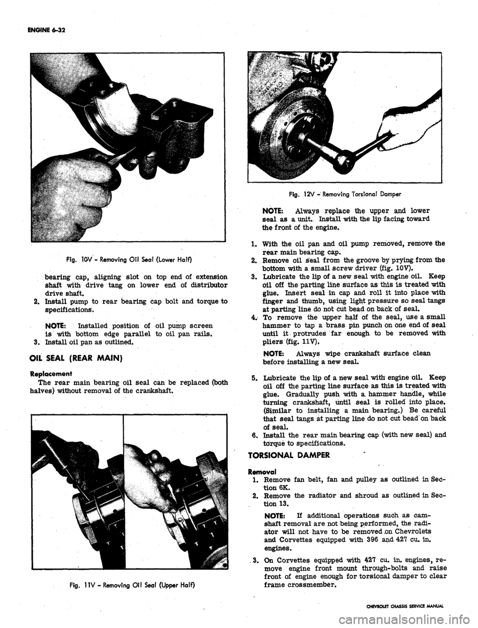
Remove oil seal from the groove by prying from the
bottom with a small screw driver (fig. 10V).
Lubricate the lip of a new seal with engine oil. Keep
oil off the parting line surface as this is treated with
glue. Insert seal in cap and roll it into place with
finger and thumb, using light pressure so seal tangs
at parting line do not cut bead on back of seal.
To remove the upper half of the seal, use a small
hammer to tap a brass pin punch on one end of seal
until it protrudes far enough to be removed with
pliers (fig. 11V).
NOTE:
Always wipe crankshaft surface clean
before installing a new seal.
1.
2.
3.
5.
Fig.
1IV - Removing Oil Seal (Upper Half)
Lubricate the lip of a new seal with engine oil. Keep
oil off the parting line surface as this is treated with
glue. Gradually push with a. hammer handle, while
turning crankshaft, until seal is rolled into place.
(Similar to installing a main bearing.) Be careful
that seal tangs at parting line do not cut bead on back
of seal.
6. Install the rear main bearing cap (with new seal) and
torque to specifications.
TORSIONAL DAMPER
Removal
1.
Remove fan belt, fan and pulley as outlined in Sec-
tion 6K.
2.
Remove the radiator and shroud as outlined in Sec-
tion 13.
NOTE:
If additional operations such as cam-
shaft removal are not being performed, the radi-
ator will not have to be removed
.on
Chevrolets
and Corvettes equipped with 396 and 427 cu. in.
engines.
. 3. On Corvettes equipped with 427 cu. in. engines, re-
move engine front mount through-bolts and raise
front of engine enough for torsional damper to clear
frame crossmember.
CHEVROLET CHASSIS SERVICE MANUAL
Page 306 of 659
SECTION 6K
ENGINE COOLING
INDEX
Page
General Description . . . 6K-1
Maintenance and Adjustments 6K-1
Coolant Level 6K-1
Coolant System Checks 6K-1
Periodic Maintenance 6K-2
Cleaning 6K-2
Reverse Flushing 6K-2
Radiator 6K-2
Page
Cylinder Block and Cylinder Head 6K-2
Hot Water Heater 6K-2
Fan Belt . 6K-2
Adjustment ....". 6K-2
Thermostat . 6K-2
Replacement 6K-2
Water Pump. . . . 6K-3
Removal 6K-3
Installation 6K-3
GENERAL DESCRIPTION
A pressure cooling system is provided for on all
models by a pressure type radiator cap (fig. 1). The
pressure type radiator cap used is designed to hold a
pressure above atmospheric pressure in the cooling
system. Excessive pressure is relieved by a valve within
the cap that opens to radiator overflow.
The water pump is a ball bearing, centrifugal vane
impeller type. It requires no care other than to make
certain the air vent at the top of the housing and the drain
holes in the bottom do not become plugged with dirt or
grease. Removal and installation of the water pump is
covered in this section. For overhaul procedures of the
water pump refer to Section 6K of the Passenger Chassis
Overhaul Manual.
For radiator, refer to Section 13 of this manual For
radiator shroud, refer to Section 11 of this manual.
Fig.
I—Pressure Radiator Cap
MAINTENANCE AND ADJUSTMENTS
Coolant Level
The radiator coolant level should only be checked when
the engine is cool, particularly on cars equipped with air
conditioning. If the radiator cap is removed from a hot
cooling system, serious personal injury may result
The cooling system fluid level should be maintained
one inch below the bottom of the filler neck of the radia-
tor when cooling system is cold, or at the bottom of the
filler neck when the system is warm. It is very impor-
tant that the correct fluid level be maintained. The seal-
ing ability of the radiator cap is affected when the cooling
level is too high.
All passenger car cooling systems are pressurized
with a pressure cap which permits safe engine operation
at cooling temperatures of
up
to 247°F.
When the radiator cap is removed or loosened, the
system pressure drops to atmospheric, and the heat
which had caused water temperature to be higher than
212°F, will be dissipated by conversion of water to
steam. Inasmuch as the steam may form in the engine
water passages, it will blow coolant out of the radiator
upper hose and top tank, necessitating coolant replace-
ment Engine operating temperatures higher than the
normal boiling point of water are in no way objectionable
so long as the coolant level is satisfactory when the
engine is cooL
Upon repeated coolant loss, the pressure radiator cap
and seat should be checked for sealing ability. Also, the
cooling system should be checked for loose hose con-
nections, defective hoses, gasket leaks, etc.
Coolant System Checks
1.
Test for restriction in the radiator, by warming the
engine up and then turning the engine off and feeling
the radiator. The radiator should be hot at the top
and warm at the bottom, with an even temperature
rise from bottom to top. Cold spots in the radiator
indicate clogged sections.
2.
Water pump operation may be checked by running the
engine while squeezing the upper radiator hose. A
pressure surge should be felt Check for a plugged
vent-hole in pump.
NOTE:
A defective head gasket may allow ex-
haust gases to leak into the cooling system.
This is particularly damaging to the cooling
system as the gases combine with the water to
form acids which are particularly harmful to
the radiator and engine.
3.
To check for exhaust leaks into the cooling system,
drain the system until the water level stands just
above the top of the cylinder head, then disconnect
the upper radiator hose and remove the thermostat
and fan belt. Start the engine and quickly accelerate
several times. At the same time note any appreci-
able water rise or the appearance of bubbles which
CHEVROLET CHASSIS SERVICE MANUAL