check engine CHEVROLET CAMARO 1967 1.G Chassis Service Manual
[x] Cancel search | Manufacturer: CHEVROLET, Model Year: 1967, Model line: CAMARO, Model: CHEVROLET CAMARO 1967 1.GPages: 659, PDF Size: 114.24 MB
Page 276 of 659
ENGINE 6-11
Fig.
18 - Cooling System Pressure Test
Carburetor
Refer to Section 6M to perform adjustments such as
idle vent, float level, pump rod and secondary valve.
Fuel Pump
If the owner has complained of poor high speed per-
formance, the fuel pump may be at fault. Too low a
pump pressure or volume will cause a high speed "miss"
because of lack of fuel delievered to the carburetor,
while too high a pressure will cause carburetor flooding.
Check fuel pump as outlined in Section 6M.
Cooling System
The following test may be performed with pressure
testing equipment available commercially for this pur-
pose.
This test provides an excellent means of detecting
internal or external leaks within the cooling system.
1.
Remove radiator cap.
2.
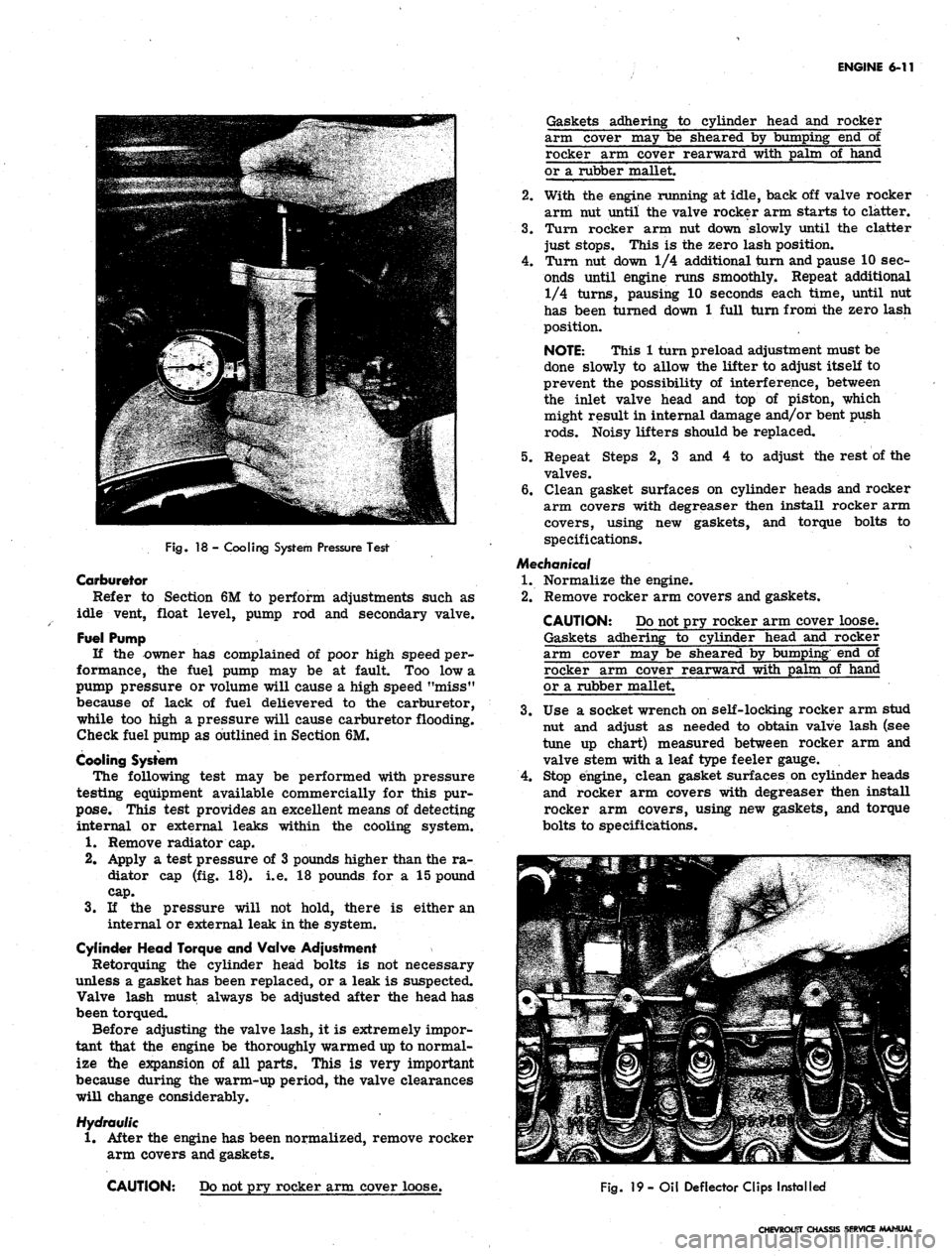
Apply a test pressure of 3 pounds higher than the ra-
diator cap (fig. 18). i.e. 18 pounds for a 15 pound
cap.
3.
If the pressure will not hold, there is either an
internal or external leak in the system.
Cylinder Head Torque and Valve Adjustment
Retorquing the cylinder head bolts is not necessary
unless a gasket has been replaced, or a leak is suspected.
Valve lash must always be adjusted after the head has
been torqued.
Before adjusting the valve lash, it is extremely impor-
tant that the engine be thoroughly warmed up to normal-
ize the expansion of all parts. This is very important
because during the warm-up period, the valve clearances
will change considerably.
Hydraulic
1.
After the engine has been normalized, remove rocker
arm covers and gaskets.
CAUTION: Do not pry rocker arm cover loose.
Gaskets adhering to cylinder head and rocker
arm cover may be sheared by bumping end of
rocker arm cover rearward with palm of hand
or a rubber mallet.
2.
With the engine running at idle, back off valve rocker
arm nut until the valve rocker arm starts to clatter.
3.
Turn rocker arm nut down slowly until the clatter
just stops. This is the zero lash position.
4.
Turn nut down 1/4 additional turn and pause 10 sec-
onds until engine runs smoothly* Repeat additional
1/4 turns, pausing 10 seconds each time, until nut
has been turned down 1 full turn from the zero lash
position.
NOTE: This 1 turn preload adjustment must be
done slowly to allow the lifter to adjust itself to
prevent the possibility of interference, between
the inlet valve head and top of piston, which
might result in internal damage and/or bent push
rods.
Noisy lifters should be replaced.
5.
Repeat Steps 2, 3 and 4 to adjust the rest of the
valves.
6. Clean gasket surfaces on cylinder heads and rocker
arm covers with degreaser then install rocker arm
covers, using new gaskets, and torque bolts to
specifications.
Mechanical
1.
Normalize the engine.
2.
Remove rocker arm covers and gaskets.
CAUTION: Do not pry rocker arm cover loose.
Gaskets adhering to cylinder head and rocker
arm cover may be sheared by bumping end of
rocker arm cover rearward with palm of hand
or a rubber mallet.
3.
Use a socket wrench on self-locking rocker arm stud
nut and adjust as needed to obtain valve lash (see
tune up chart) measured between rocker arm and
valve stem with a leaf type feeler gauge.
4.
Stop engine, clean gasket surfaces on cylinder heads
and rocker arm covers with degreaser then install
rocker arm covers, using new gaskets, and torque
bolts to specifications.
Fig.
19
- Oil Deflector Clips Installed
CHEVROLET CHASSIS SERVICE MANUAL
Page 279 of 659
ENGINE 6-14
b.
Bolt transmission to engine, then raise engine and
transmission assembly and install flywheel to
converter attaching bolts.
c. Install converter
housing*
underpan and starter.
3.
Tilt and lower engine and transmission assembly into
the chassis as a unit, guiding engine to align front
mounts with frame supports.
4.
Install front mount through bolts and torque to
specifications.
5.
Raise engine enough to install rear crossmember,
then install crossmember, install rear mount, lower
engine and torque bolts to specifications.
6. Remove lifting device and lifting adapter then install
rocker arm cover as outlined.
7.
On synchromesh equipped vehicles, install clutch
cross shaft engine bracket, then adjust and connect
clutch as outlined in Section 7.
8. Connect:
• Speedometer cable.
• Shift linkage at transmission.
9; Install propeller shaft.
10.
Remove jack stands and lower vehicle.
11.
Connect:
Power steering pump lines (if disconnected).
Vacuum line to power brake unit (if disconnected).
Fuel line at fuel pump.
Exhaust pipe at manifold flange.
Accelerator linkage at manifold bellcrank.
12.
Connect wires at:
Coil
Oil pressure switch
Temperature switch
Delcotron
Starter solenoid
13.
Install pulley, fan blade and fan belt as outlined in
Section 6K.
14.
Install radiator and shroud as outlined in Section 13.
15.
Install and adjust hood as outlined in Section 11.
16.
Connect battery cables.
17.
Fill with coolant, engine oil and transmission oil,
then start engine and check for leaks.
18.
Perform necessary adjustments and install air
cleaner.
MANIFOLD ASSEMBLY
Removal
1.
Remove air cleaner.
2.
Disconnect both throttle rods at bellcrank and re-
move throttle return spring.
3.
Disconnect fuel and vacuum lines at carburetor.
Disconnect choke cable on \A engines.
4.
Disconnect crankcase ventilation hose at rocker arm
cover.
5.
Disconnect exhaust pipe at manifold flange and dis-
card packing.
6. Remove manifold attaching bolts and clamps then
remove manifold assembly and discard gaskets.
7.
Check for cracks in manifold castings.
8. If necessary to replace either intake or exhaust
manifolds, separate them by removing one bolt and
two nuts at center of assembly. Reassemble mani-
folds using a new gasket. Tighten finger tight and
torque to specifications after assembly to cylinder
head. Transfer all necessary parts.
Installation
1.
Clean gasket surfaces on cylinder head and
manifolds*
2.
Position new gasket over manifold end studs on head
and carefully install the manifold in position making
sure the gaskets are in place.
3.
Install bolts and clamps while holding manifold in
place with hand.
4.
Torque bolts to specifications.
NOTE: On L6 engines center bolt and end bolt
torque differ.
5.
Connect exhaust pipe to manifold using a new
packing.
6. Connect crankcase ventilation hose at rocker arm
cover.
7.
Connect fuel and vacuum lines at carburetor.
8. On L4 engines connect choke cable and adjust as out-
lines in Section 6M.
9. Connect throttle rods at bellcrank and install throttle
return spring.
10.
Install air cleaner, start engine, check for leaks and
adjust carburetor idle speed and mixture.
ROCKER ARM COVER
Removal
1.
Disconnect crankcase ventilation hose(s) at rocker
arm cover.
2.
Remove air cleaner.
3.
Disconnect temperature wire from rocker arm cover
clips.
4.
Remove rocker arm cover. '
CAUTION: Do Not pry rocker arm cover loose
Gaskets adhering to cylinder head and rocker
arm cover may be sheared by bumping end of
rocker arm cover rearward with palm of hand or
a rubber mallet.
Installation
1.
Clean gasket surfaces on cylinder head and rocker
arm cover with degreaser then, using anew gasket,
install rocker arm cover and torque bolts to
specifications.
2.
Connect temperature wire at rocker arm cover clips.
3.
Install air cleaner.
4.
Connect crankcase ventilation hoses.
VALVE MECHANISM
Removal
1.
Remove rocker arm cover as outlined.
2.
Remove rocker arm nuts, rocker arm
balls,
rocker
arms and push rods.
NOTE:
Place rocker arms, rocker arm balls
and push rods in a rack so they may be rein-
stalled in the same location.
Installation and Adjustment
NOTE:
Whenever new rocker arms and/or
rocker arm balls are being installed, coat bear-
ing surfaces of rocker arms and rocker arm
balls with Molykote or its equivalent.
1.
Install push rods,
socket.
Be sure push rods seat in lifter
CHEVROLET CHASSIS SERVICE MANUAL
Page 280 of 659
ENGINE 6-15
2.
Install rocker arms, rocker arm balls and rocker
arm
nuts.
\
Tighten rocker arm nuts until all lash is
eliminated. .
3.
Adjust valves when lifter is on base circle of cam-
shaft lobe as follows:
a. Mark distributor housing, with chalk, at each cyl-
inder position (plug wire) then disconnect plug
wires at spark plugs and coil and remove distri-
butor cap and plug wire assembly (if not previ-
ously done).
b.
Crank engine until distributor rotor points to
number one cylinder position and breaker points
are open. Both valves on number one cylinder
may now be adjusted.
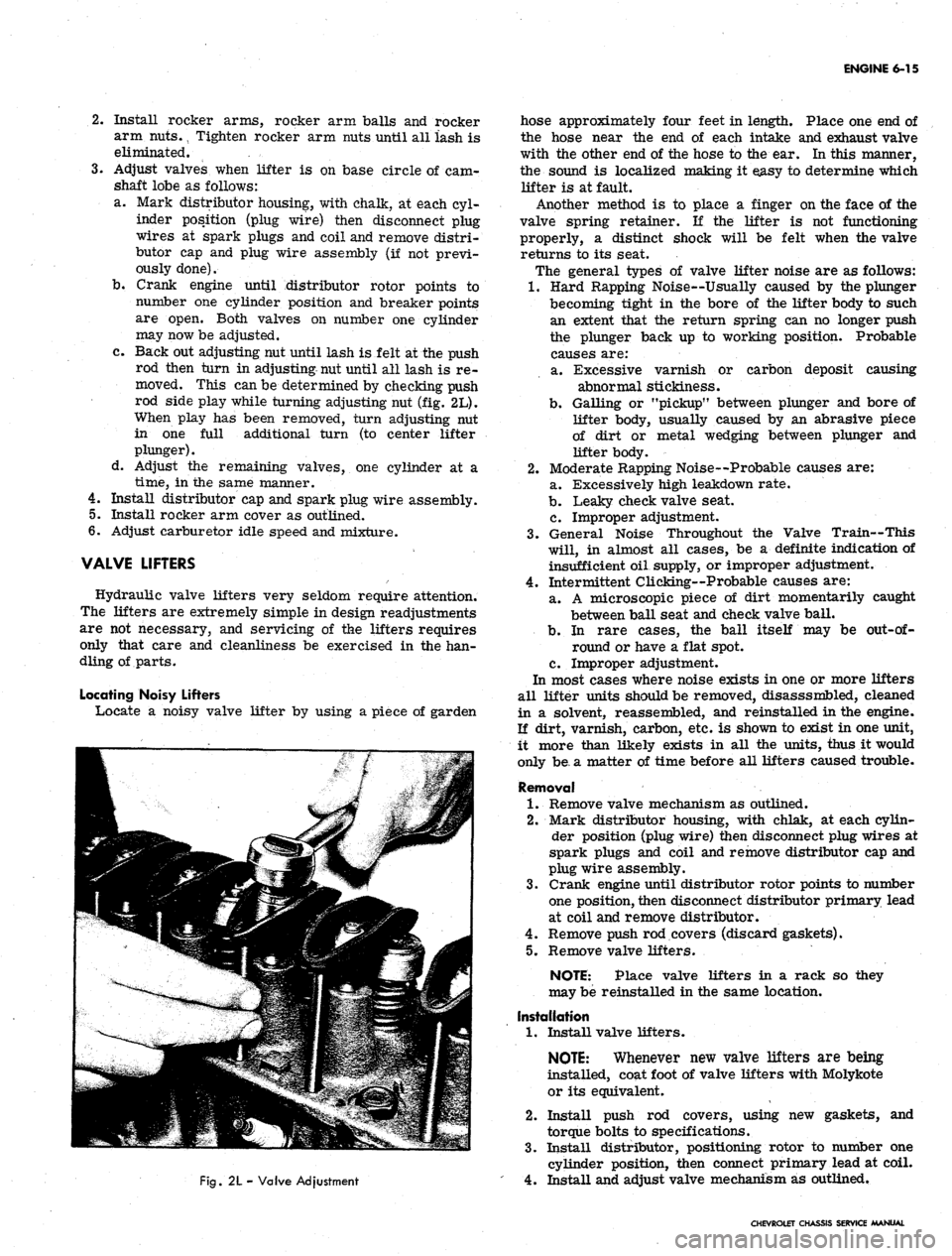
c. Back out adjusting nut until lash is felt at the push
rod then turn in adjusting nut until all lash is re-
moved. This can be determined by checking push
rod side play while turning adjusting nut (fig. 2L).
When play has been removed, turn adjusting nut
in one full additional turn (to center lifter
plunger).
d. Adjust the remaining valves, one cylinder at a
time,
in the same manner.
4.
Install distributor cap and spark plug wire assembly.
5.
Install rocker arm cover as outlined.
6. Adjust carburetor idle speed and mixture.
VALVE LIFTERS
Hydraulic valve lifters very seldom require attention.
The lifters are extremely simple in design readjustments
are not necessary, and servicing of the lifters requires
only that care and cleanliness be exercised in the han-
dling of parts.
Locating Noisy Lifters
Locate a noisy valve lifter by using a piece of garden
Fig.
2L - Valve Adjustment
hose approximately four feet in length. Place one end of
the hose near the end of each intake and exhaust valve
with the other end of the hose to the ear. In this manner,
the sound is localized making it easy to determine which
lifter is at fault.
Another method is to place a finger on the face of the
valve spring retainer. If the lifter is not functioning
properly, a distinct shock will be felt when the valve
returns to its seat.
The general types of valve lifter noise are as follows:
1.
Hard Rapping Noise--Usually caused by the plunger
becoming tight in the bore of the lifter body to such
an extent that the return spring can no longer push
the plunger back up to working position. Probable
causes are:
a. Excessive varnish or carbon deposit causing
abnormal stickiness.
b.
Galling or "pickup" between plunger and bore of
lifter body, usually caused by an abrasive piece
of dirt or metal wedging between plunger and
lifter body.
2.
Moderate Rapping Noise--Probable causes are:
a. Excessively high leakdown rate.
b.
Leaky check valve seat.
c. Improper adjustment.
3.
General Noise Throughout the Valve Train—This
will, in almost all cases, be a definite indication of
insufficient oil supply, or improper adjustment.
4.
Intermittent Clicking—Probable causes are:
a. A microscopic piece of dirt momentarily caught
between ball seat and check valve ball.
b.
In rare cases, the ball itself may be
out-of-
round or have a flat spot.
c. Improper adjustment.
In most cases where noise exists in one or more lifters
all lifter units should be removed, disasssmbled, cleaned
in a solvent, reassembled, and reinstalled in the engine.
If dirt, varnish, carbon, etc. is shown to exist in one unit,
it more than likely exists in all the units, thus it would
only be, a matter of time before all lifters caused trouble.
Removal
1.
Remove valve mechanism as outlined.
2.
Mark distributor housing, with chlak, at each cylin-
der position (plug wire) then disconnect plug wires at
spark plugs and coil and remove distributor cap and
plug wire assembly.
3.
Crank engine until distributor rotor points to number
one position, then disconnect distributor primary lead
at coil and remove distributor.
4.
Remove push rod covers (discard gaskets).
5.
Remove valve lifters.
NOTE: Place valve lifters in a rack so they
may be reinstalled in the same location.
Installation
1.
Install valve lifters.
NOTE:
Whenever new valve lifters are being
installed, coat foot of valve lifters with Molykote
or its equivalent.
2.
Install push rod covers, using new gaskets, and
torque bolts to specifications.
3.
Install distributor, positioning rotor to number one
cylinder position, then connect primary lead at coil.
4.
Install and adjust valve mechanism as outlined.
CHEVROLET CHASSIS SERVICE MANUAL
Page 283 of 659
ENGINE 6-18
NOTE:
Bolts into crankcase cover should be
installed last. They are installed at an angle
and holes line up after rest of pan bolts are
snugged up.
Chevrolet and Camaro
a. If crankshaft was rotated while pan was off, place
timing mark at 6:00 o'clock position.
b.
Install oil pan and torque bolts to specifications.
c. Using a suitable jack (and a block of wood to prevent
damaging oil pan) raise engine enough to remove 2" x
4"
wood blocks, then lower engine.
d. On vehicles equipped with automatic transmission
install converter housing underpan, then connect
transmission cooler lines.
e. Install and connect starter.
f. Lower vehicle and install fan blades as outlined in
Section 6K.
g. Connect upper and lower radiator hoses.
h. Install through bolts in engine front mounts.
i. Connect battery positive cable.
j.
Fill radiator with coolant and fill engine with oil,
then start engine and check for leaks.
Chevelie
* a. Install oil pan and torque bolts to specifications.
b.
On vehicles equipped with automatic transmission,
install converter housing underpan.
c. Install starter.
d. Install engine as outlined.
Chevy II
a. Install oil pan and torque bolts to specifications.
Fig.
7L- Removing Oil Sea! (Lower Half)
Fig.
8L - Removing Oil Seal (Upper Half)
b.
On L6 engines, install front crossmember.
c. Connect steering idler arm.
d. Install starter and connect wires.
e. Connect battery cable, fill with oil, start engine and
check for leaks.
OIL PUMP
Removal
1.
Remove oil pan as outlined.
2.
Remove two flange mounting bolts, pickup pipe bolt,
then remove pump and screen as an assembly.
Installation
1.
Align oil pump drive shafts to match with distributor
tang, then install oil pump to block positioning flange
over distributor lower bushing. Use no gasket.
NOTE:
Oil pump should slide easily into place,
if not, remove and reposition slot to align with
distributor tang.
2.
Install oil pan using new gaskets and seals as
outlined.
CHEVROLET CHASSIS SERVICE MANUAL
Page 285 of 659
ENGINE 6-20
Fig.
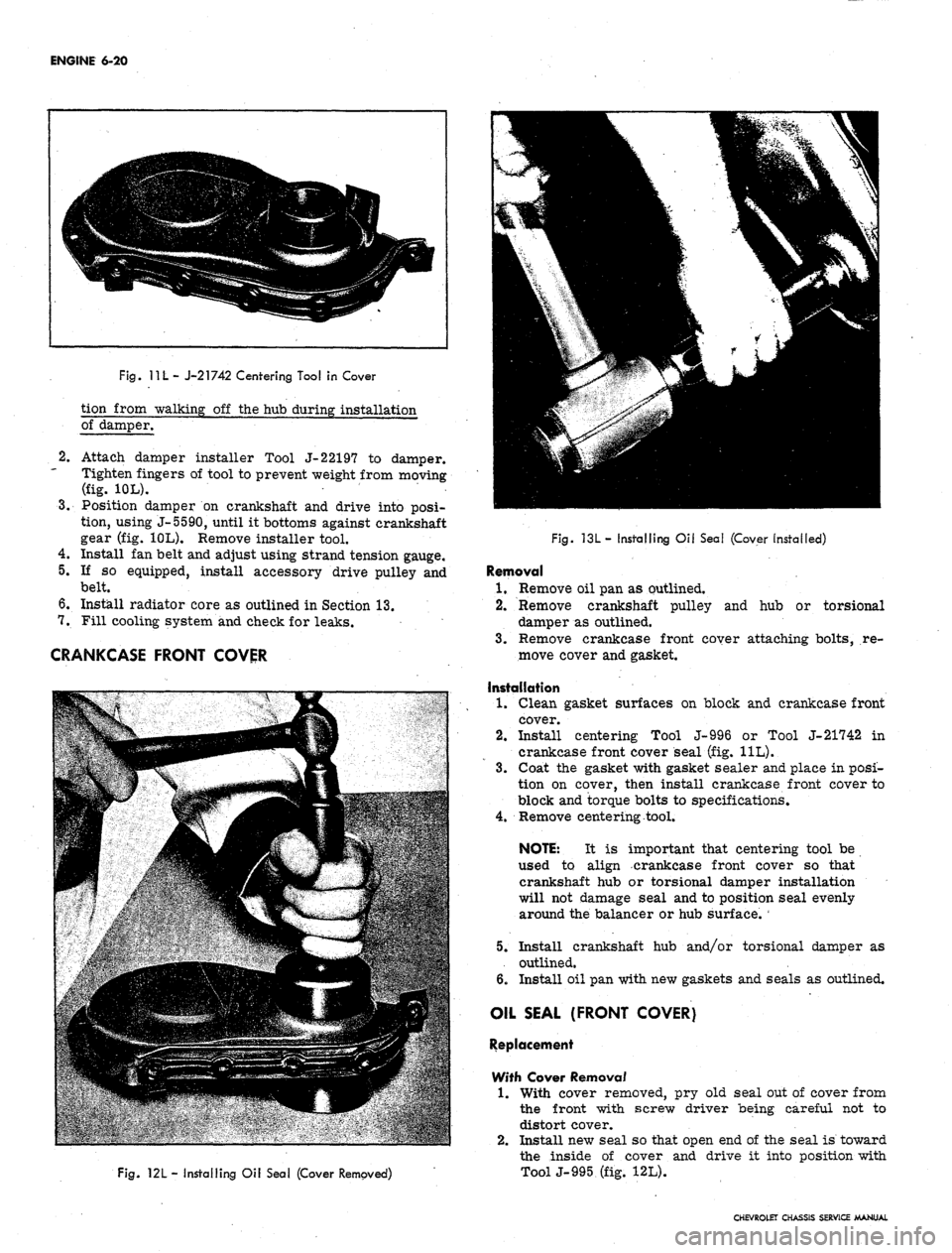
11 L
- J-21742 Centering Tool in Cover
tion from walking off the hub during installation
of damper.
2.
3.
Attach damper installer Tool J-22197 to damper.
Tighten fingers of tool to prevent weight from moving
(fig. 10L).
Position damper on crankshaft and drive into posi-
tion, using J-5590, until it bottoms against crankshaft
gear (fig. 10L). Remove installer tool.
4.
Install fan belt and adjust using strand tension gauge.
5.
If so equipped, install accessory drive pulley and
belt.
6. Install radiator core as outlined in Section 13.
7.
Fill cooling system and check for leaks.
CRANKCASE FRONT COVER
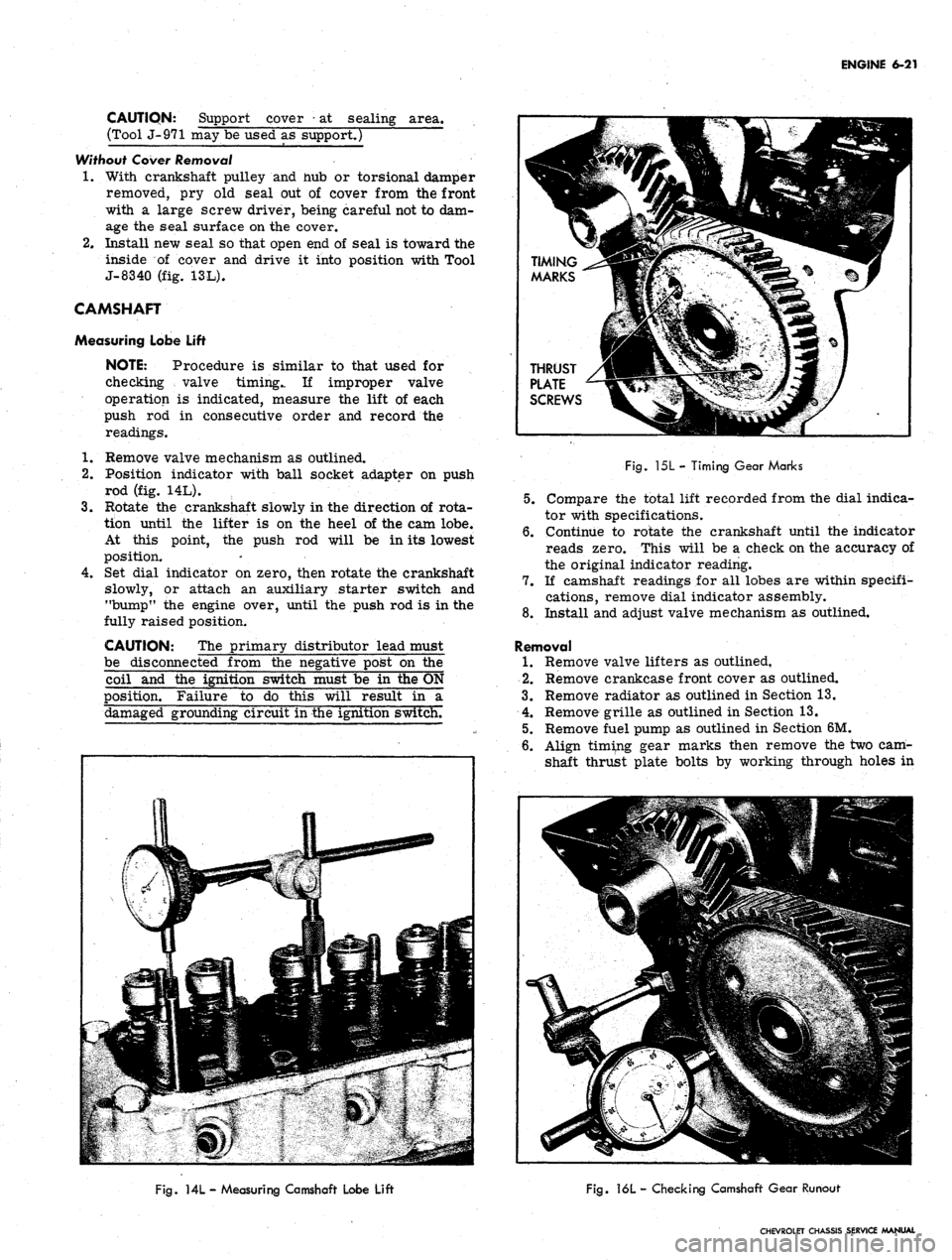
Fig.
121
- Installing Oil Seal (Cover Removed)
Fig. 13L- Installing Oil Seal (Cover installed)
Removal
1.
Remove oil pan as outlined.
2.
Remove crankshaft pulley and hub or torsional
damper as outlined.
3.
Remove crankcase front coyer attaching bolts, re-
move cover and gasket.
Installation
1.
Clean gasket surfaces on block and crankcase front
cover.
2.
Install centering Tool J-996 or Tool J-21742 in
crankcase front cover seal (fig. 11L).
3.
Coat the gasket with gasket sealer and place in posi-
tion on cover, then install crankcase front cover to
block and torque bolts to specifications.
4.
Remove centering tool.
NOTE: It is important that centering tool be
used to align crankcase front cover so that
crankshaft hub or torsional damper installation
will not damage seal and to position seal evenly
around the balancer or hub surface.
5.
Install crankshaft hub and/or torsional damper as
outlined.
6. Install oil pan with new gaskets and seals as outlined.
OIL SEAL (FRONT COVER)
Replacement
With Cover Removal
1.
With cover removed, pry old seal out of cover from
the front with screw driver being careful not to
distort cover.
2.
Install new seal so that open end of the seal is toward
the inside of cover and drive it into position with
ToolJ-995 (fig. 12L).
CHEVROLET CHASSIS SERVICE MANUAL
Page 286 of 659
ENGINE 6-21
CAUTION: Support cover
•
at sealing area.
(Tool J-971 may be used as support.)
Without Cover
Removal
1.
With crankshaft pulley and nub or torsional damper
removed, pry old seal out of cover from the front
with a large screw driver, being careful not to dam-
age the seal surface on the cover.
2.
Install new seal so that open end of seal is toward the
inside of cover and drive it into position with Tool
J-8340 (fig. 13L).
CAMSHAFT
Measuring Lobe Lift
NOTE: Procedure is similar to that used for
checking valve timing.. If improper valve
operation is indicated, measure the lift of each
push rod in consecutive order and record the
readings.
1.
Remove valve mechanism as outlined.
2.
Position indicator with ball socket adapter on push
rod (fig. 14L).
3.
Rotate the crankshaft slowly in the direction of rota-
tion until the lifter is on the heel of the cam lobe.
At this point, the push rod will be in its lowest
position.
4.
Set dial indicator on zero, then rotate the crankshaft
slowly, or attach an auxiliary starter switch and
"bump" the engine over, until the push rod is in the
fully raised position.
CAUTION: The primary distributor lead must
be disconnected from the negative post on the
coil and the ignition switch must be in the ON
position. Failure to do this will result in a
damaged grounding circuit in the ignition switch.
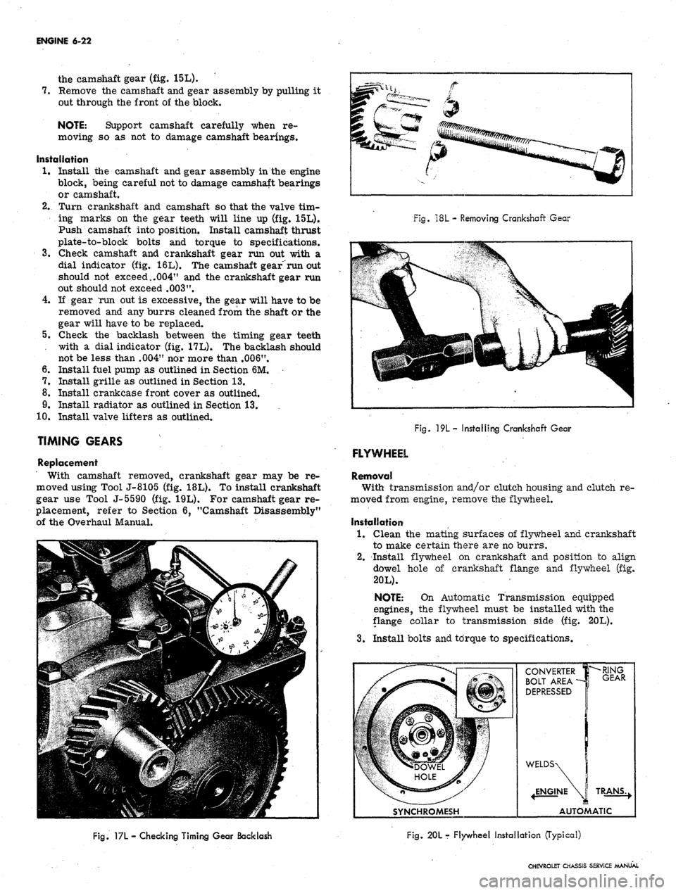
Fig.
15L - Timing Gear Marks
5.
Compare the total lift recorded from the dial indica-
tor with specifications.
6. Continue to rotate the crankshaft until the indicator
reads zero. This will be a check on the accuracy of
the original indicator reading.
7.
If camshaft readings for all lobes are within specifi-
cations, remove dial indicator assembly.
8. Install and adjust valve mechanism as outlined.
Removal
1.
Remove valve lifters as outlined,
2.
Remove crankcase front cover as outlined.
3.
Remove radiator as outlined in Section 13.
4.
Remove grille as outlined in Section 13.
5.
Remove fuel pump as outlined in Section 6M.
6. Align timing gear marks then remove the two cam-
shaft thrust plate bolts by working through holes in
Fig.
ML - Measuring Camshaft Lobe Lift
Fig.
16L - Checking Camshaft Gear Runout
CHEVROLET CHASSIS SERVICE MANUAL
Page 287 of 659
ENGINE 6-22
the camshaft gear (fig. 15L).
7.
Remove the camshaft and gear assembly by pulling it
out through the front of the block.
NOTE: Support camshaft carefully when re-
moving so as not to damage camshaft bearings.
Installation
1.
Install the camshaft and gear assembly in the engine
block, being careful not to damage camshaft bearings
or camshaft.
2.
Turn crankshaft and camshaft so that the valve tim-
ing marks on the gear teeth will line up (fig. 15L).
Push camshaft into position. Install camshaft thrust
plate-to-block bolts and torque to specifications.
3.
Check camshaft and crankshaft gear run out with a
dial indicator (fig. 16L). The camshaft gear"run out
should not exceed,.004" and the crankshaft gear run
out should not exceed
.003".
4.
If gear mm out is excessive, the gear will have to be
removed and any burrs cleaned from the shaft or the
gear will have to be replaced.
5.
Check the backlash between the timing gear teeth
with a dial indicator (fig. 17L). The backlash should
not be less than .004" nor more than .006".
6. Install fuel pump as outlined in Section 6M.
7.
Install grille as outlined in Section 13.
8. Install crankcase front cover as outlined.
9. Install radiator as outlined in Section 13.
10.
Install valve lifters as outlined.
TIMING GEARS
Replacement
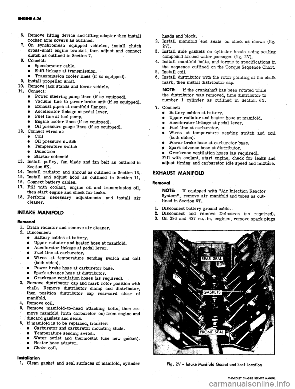
With camshaft removed, crankshaft gear may be re-
moved using Tool J-8105 (fig. 18L). To install crankshaft
gear use Tool J-5590 (fig. 19L). For camshaft gear re-
placement, refer to Section 6, "Camshaft Disassembly"
of the Overhaul Manual.
Fig.
18L
- Removing Crankshaft Gear
Fig.
19L- Installing Crankshaft Gear
FLYWHEEL
Removal
With transmission and/or clutch housing and clutch re-
moved from engine, remove the flywheel.
Installation
1.
Clean the mating surfaces of flywheel and crankshaft
to make certain there are no burrs.
2.
Install flywheel on crankshaft and position to align
dowel hole of crankshaft flange and flywheel (fig.
20L).
NOTE: On Automatic Transmission equipped
engines, the flywheel must be installed with the
flange collar to transmission side (fig. 20L).
3.
Install bolts and torque to specifications.
SYNCHROMESH
CONVERTER
BOLT AREA -
DEPRESSED
•RING
GEAR
TRANS.,
AUTOMATIC
Fig. 17L
—
Checking Timing Gear Backlash
Fig. 20L r Flywheel Installation (Typical)
CHEVROLET CHASSIS SERVICE MANUAL
Page 291 of 659
ENGINE 6-26
6. Remove lifting device and lifting adapter then install
rocker arm covers as outlined.
7.
On synchromesh equipped vehicles, install clutch
cross-shaft engine bracket, then adjust and connect
clutch as outlined in Section 7.
8. Connect:
• Speedometer cable.
• Shift linkage at transmission.
• Transmission cooler lines (if so equipped).
9. Install propeller shaft.
10.
Remove jack stands and lower vehicle.
11.
Connect: \ '
Power steering pump lines (if so equipped).
Vacuum line to power brake unit (if so equipped).
Exhaust pipes at manifold flanges.
Accelerator linkage at pedal lever.
Fuel line at fuel pump.
Engine cooler lines (if so equipped).
Oil pressure gauge lines (if so equipped).
12.
Connect wires at:
Coil
Oil pressure switch
Temperature switch
Delcotron
Starter solenoid
13.
Install pulley, fan blade and fan belt as outlined in
Section 6K.
14.
Install radiator and shroud as outlined in Section 13.
15.
Install and adjust hood as outlined in Section 11.
16.
Connect battery cables.
17.
Fill with coolant, engine oil and transmission oil,
then start engine and check for leaks.
18.
Perform necessary adjustments and install air
cleaner.
INTAKE MANIFOLD
Removal
1.
Drain radiator and remove air cleaner.
2.
Disconnect:
Battery cables at battery.
Upper radiator and heater hose at manifold.
Accelerator linkage at pedal lever.
Fuel line at carburetor. ;
Wires at temperature sending switch and coil
(both sides).
Power brake hose at carburetor base.
Spark advance hose at distributor.
Crankcase ventilation hoses (as required).
3.
Remove distributor cap and mark rotor position with
chalk. Remove distributor clamp and distributor,
then position distributor cap rearward clear of
manifold.
4.
Remove coil.
5.
Remove manifold-to-head attaching bolts, then re^
move manifold, (with carburetor on) from engine and
discard gaskets and seals.
6. If manifold is to be replaced,,transfer:
Carburetor and carburetor mounting studs.
Temperature sending switch.
Water outlet and thermostat (use new gasket).
Heater hose adapter.
Choke coil.
Installation
1.
Clean gasket and seal surfaces of manifold, cylinder
heads and block.
2.
Install manifold end seals on block as shown (fig.
2V).
3.
Install side gaskets on cylinder heads using sealing
compound around water passages (fig. 2V).
4.
Install manifold bolts, and torque to specifications in
the sequence outlined on the Torque Sequence Chart.
5.
Install coil.
6. Install distributor with the rotor pointing at the chalk
mark, then install distributor cap.
NOTE:
If the crankshaft has been rotated while
the distributor was removed, time distributor to
number 1 cylinder as outlined in Section 6Y.
7.
Connect:
Battery cables at battery.
Upper radiator and heater hose at manifold.
Accelerator linkage at pedal lever.
Fuel line at carburetor.
Wires at temperature sending switch and coil
(both sides)!
Power brake hose at carburetor base.
Spark advance hose at distributor.
Crankcase ventilation hoses (as required).
Fill with coolant, start engine, check for leaks and
adjust timing and carburetor idle speed and mixture.
EXHAUST MANIFOLD
Removal
NOTE:
If equipped with "Air Injection Reactor
System", remove air manifold and tubes as out-
lined in Section 6T.
1.
Disconnect battery ground cable.
-
2.
Disconnect and remove Delcotron (as required).
3.
On 396 and 427 cu. in. engines, remove spark plugs
Fig. 2V - Intake Manifold Gasket and Seal Location
CHEVROLET CHASSIS SERVICE MANUAL
Page 292 of 659
ENGINE 6-27
and spark plug shields.
4.
Remove exhaust manifold flange nuts, then lower ex-
haust pipe assembly (hang exhaust pipe from frame
with wire).
5.
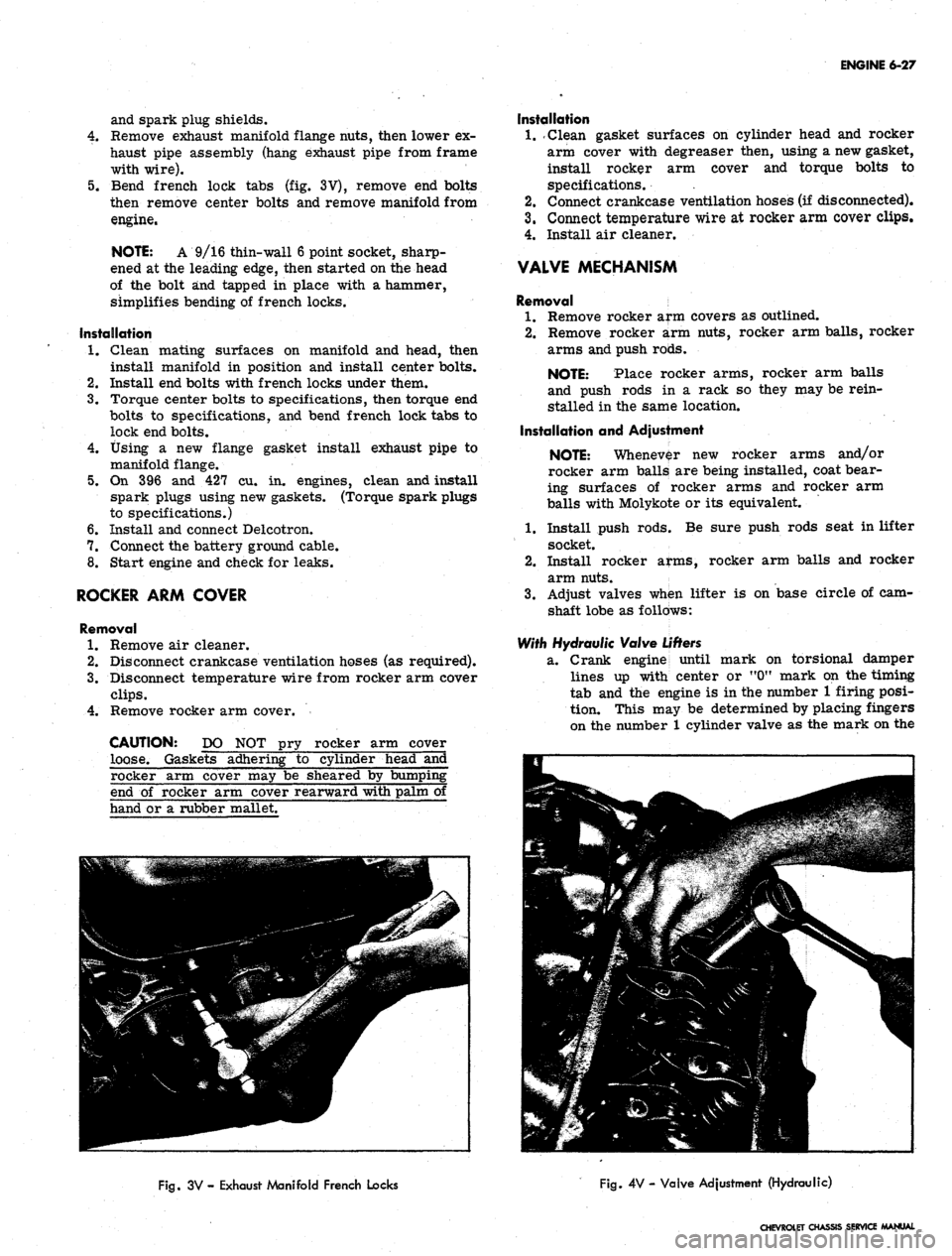
Bend french lock tabs (fig. 3V), remove end bolts
then remove center bolts and remove manifold from
engine.
NOTE: A 9/16 thin-wall 6 point socket, sharp-
ened at the leading edge, then started on the head
of the bolt and tapped in place with a hammer,
simplifies bending of french locks.
Installation
1.
Clean mating surfaces on manifold and head, then
install manifold in position and install center bolts.
2.
Install end bolts with french locks under them.
3.
Torque center bolts to specifications, then torque end
bolts to specifications, and bend french lock tabs to
lock end bolts.
4.
Using a new flange gasket install exhaust pipe to
manifold flange.
5.
On 396 and 427 cu. in. engines, clean and install
spark plugs using new gaskets. (Torque spark plugs
to specifications.)
6. Install and connect Delcotron.
7.
Connect the battery ground cable.
8. Start engine and check for leaks.
ROCKER ARM COVER
Removal
1.
Remove air cleaner.
2.
Disconnect crankcase ventilation hoses (as required).
3.
Disconnect temperature wire from rocker arm cover
clips.
4.
Remove rocker arm cover.
CAUTION: DO NOT pry rocker arm cover
loose. Gaskets adhering to cylinder head and
Installation
1.
.Clean gasket surfaces on cylinder head and rocker
arm cover with degreaser then, using a new gasket,
install rocker arm cover and torque bolts to
specifications. .
2.
Connect crankcase ventilation hoses (if disconnected).
3.
Connect temperature wire at rocker arm cover clips.
4.
Install air cleaner.
VALVE MECHANISM
Removal
1.
Remove rocker arm covers as outlined.
2.
Remove rocker arm nuts, rocker arm balls, rocker
arms and push rods.
NOTE: Place rocker arms, rocker arm balls
and push rods in a rack so they may be rein-
stalled in the same location.
Installation and Adjustment
NOTE: Whenever new rocker arms and/or
rocker arm balls are being installed, coat bear-
ing surfaces of rocker arms and rocker arm
balls with Molykote or its equivalent.
1.
Install push rods; Be sure push rods seat in lifter
socket.
2.
Install rocker arms, rocker arm balls and rocker
arm nuts.
3.
Adjust valves when lifter is on base circle of cam-
shaft lobe as follows:
With Hydraulic Valve
Lifters
2L.
Crank engine until
mark on torsional damper
lines up with center or "0M mark on the timing
tab and the engine is in the number 1 firing posi-
tion. This may be determined by placing fingers
on the number 1 cylinder valve as the mark on the
rocker arm cover may be sheared by bumpii
end of rocker arm cover rearward with palm
hand or a rubber mallet.
Fig.
3V - Exhaust Manifold French Locks
Fig.
4V - Valve Adjustment (Hydraulic)
CHEVROLET CHASSIS SERVICE MANUAL
Page 294 of 659
ENGINE 6-29
an extent that the return spring can no longer push
the plunger back up to working position. Probable
causes are:
a. Excessive varnish or carbon deposit causing ab-
normal stickiness.
b.
(Sailing or "pick-up" between plunger and bore of
lifter body, usually caused by an abrasive piece of
dirt or metal wedging between plunger and lifter
body.
2.
Moderate Rapping Noise--Probable causes are:
a. Excessively high leakdown rate.
b.
Leaky check valve seat.
c. Improper adjustment.
3.
General Noise Throughout the Valve Train-rThis
will, in almost all cases, be a definite indication of
insufficient oil supply, or improper adjustment.
4.
Intermittent Clicking—Probable causes are:
a. A microscopic piece of dirt momentarily caught
between ball seat and check valve ball.
b.
In rare cases, the ball itself may be out-of-round
or have a flat spot.
c. Improper adjustment.
In most cases where noise exists in one or more lifters
all lifter units should be removed, disassembled, cleaned
in a solvent, reassembled, and reinstalled in the engine.
If dirt, corrosion, carbon, etc. is shown to exist in one
unit, it more than likely exists in all the units, thus it
would only be a matter of time before all lifters caused
trouble.
Removal
1.
Remove intake manifold as outlined.
2.
Remove valve mechanism as outlined.
3.
Remove valve lifters.
NOTE: Place valve lifters in a rack so they
may be reinstalled in the same location.
Installation
1.
Install valve lifters.
NOTE: Whenever new valve lifters are being
installed coat foot of valve lifters with Molykote
or its equivalent.
2.
Install intake manifold as outlined.
3.
Install and adjust valve mechanism as outlined.
VALVE STEM OIL SEAL AND/OR VALVE SPRING
Replacement
1.
Remove rocker arm cover(s) as outlined.
2.
Remove spark plug, rocker arm and push rod on the
cylinders to be serviced.
3.
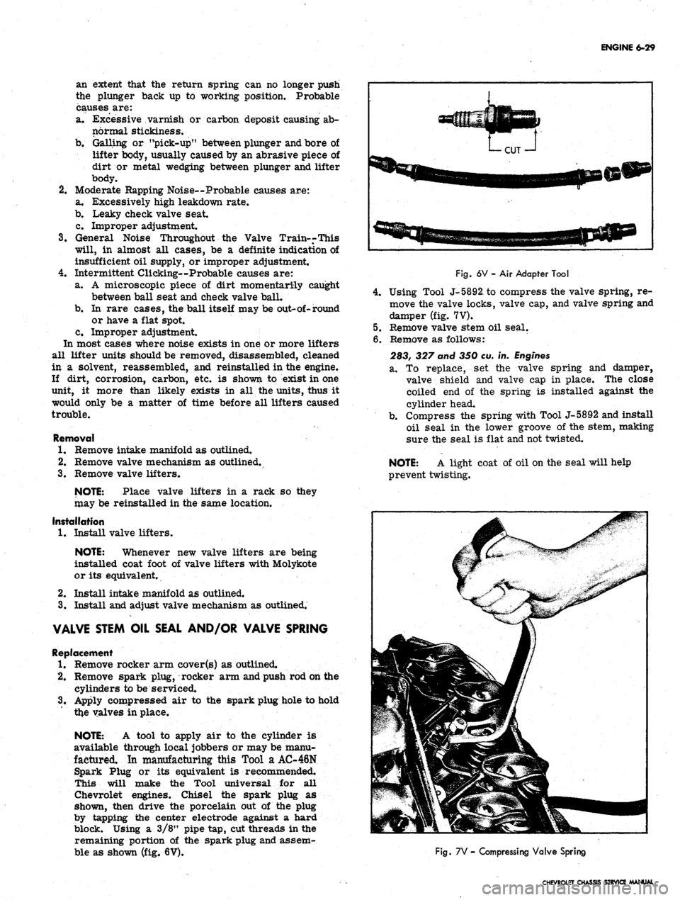
Apply compressed air to the spark plug hole to hold
tl*e valves in place.
NOTE: A tool to apply air to the cylinder is
available through local jobbers or may be manu-
factured. In manufacturing this Tool a AC-46N
Spark Plug or its equivalent is recommended.
This will make the Tool universal for all
Chevrolet engines. Chisel the spark plug as
shown, then drive the porcelain out of the plug
by tapping the center electrode against a hard
block. Using a 3/8" pipe tap, cut threads in the
remaining portion of the spark plug and assem-
ble as shown (fig. 6V).
Fig.
6V - Air Adapter Tool
4.
Using Tool J-5892, to compress the valve spring, re-
move the valve locks, valve cap, and valve spring and
damper (fig. 7V).
5.
Remove valve stem oil seal.
6. Remove as follows:
283, 327 and 350 eu. in.
Engines
a. To replace, set the valve spring and damper,
valve shield and valve cap in place. The close
coiled end of the spring is installed against the
cylinder head.
b.
Compress the spring with Tool J-5892 and install
oil seal in the lower groove of the stem, making
sure the seal is flat and not twisted.
NOTE: A light coat of oil on the seal will help
prevent twisting.
Fig.
7V - Compressing Valve Spring
CHEVROLET CHASSIS SERVICE MANUAL