service indicator CHEVROLET CAMARO 1967 1.G Chassis Service Manual
[x] Cancel search | Manufacturer: CHEVROLET, Model Year: 1967, Model line: CAMARO, Model: CHEVROLET CAMARO 1967 1.GPages: 659, PDF Size: 114.24 MB
Page 546 of 659
ELECTRICAL-BODY AND CHASSIS 12-34
5. To replace, reverse the removal procedure.
SPEEDOMETER REPLACEMENT
1.
Remove instrument cluster as previously described
in this section.
2.
Remove clock set shaft knob.
3.
Remove eight screws securing cluster housing to
bezel trim panel. Separate parts carefully observing
stack up of parts.
4.
Remove two screws securing speedometer head to
rear of cluster housing.
NOTE:
Servicing of the speedometer head
should be performed by an authorized AC Speed-
ometer Service Station.
5. To install, reverse the removal procedure..
SPEEDOMETER CABLE
Replacement or Lubricatibn
1.
Disconnect the speedometer cable from the speed-
ometer head. Remove the old cable by pulling it out
from speedometer end of conduit.
NOTE:
If old cable is broken it may be neces-
sary to remove lower piece from transmission
end of conduit.
2.
Lubricate the lower 3/4 of cable with speedometer
cable lubricant and push the cable into the conduit.
Connect the upper end to the speedometer head and
road test vehicle for proper speedometer operation.
INDICATOR LIGHT REPLACEMENT
To replace any indicator or cluster bulb, unsnap the
proper socket from rear of instrument cluster, remove
and replace bulb, and reinsert unit into rear of cluster
housing.
OIL PRESSURE INDICATOR
If the light does not come on when the ignition switch
is turned on, or if the light comes on and remains on
after the engine is started, one or more of the following
conditions is indicated:
• Low oil pressure
• High engine temperature
• Defective wiring or switch
Switch Replacement
1.
Disconnect wiring harness connector from sender
unit terminal (located in block above starter on
L-6 engines and at left front of distributor on V-8
engines).
2.
Remove sender unit, replace with new unit, and
; check operation.
GENERATOR INDICATOR
1.
Ignition on, engine not running and telltale light off.
a. Indicator bulb burned out, replace bulb.
b.
Open circuit or loose connection in the telltale
light circuit.
2.
Telltale light stays on after engine is started.
a. If indicator light does not go out at engine idle
speed, refer to Charging Systems under Engine
Electrical, Section 6Y.
TEMPERATURE (COOLING SYSTEM) INDICATOR
The temperature indicator circuit consists of two re-
motely located units, indicator gauge and engine sender
unit. The indicator gauge on all models uses a single
red light to indicate an overheated engine condition.
Engine Sender Unit Replacement
1.
Drain engine cooling system to a level below unit.
2.
Remove sender unit (located in the inlet manifold
near water pump housing on V-8 engines and in the
cylinder head near an exhaust port on L-6 engines)
and replace with new unit.
3.
Refill cooling system and check operation of unit.
CORVETTE INSTRUMENTS AND GAUGES
INDEX
Page
General Description ., 12-34
Service Operations . 12-35
Instrument Cluster ., 12-35
Fuel Gauge 12-35
Speedometer/Tachometer Service. 12-35
Temperature Gauge 12-35
Ammeter/Oil Pressure Gauges 12-35
GENERAL DESCRIPTION
All Corvette instruments and gauges are conveniently
located in the dash-mounted cluster. The entire cluster
is removable to permit servicing of the various instru-
ments and gauges. The indicator and cluster illuminating
bulbs may be replaced without removing the cluster from
the panel.
Regular maintenance is not required on the instrument
cluster or its components other than maintaining clean
and keeping the speedometer and tachometer cables
properly lubricated.
CHEVROLET CHASSIS SERVICE MANUAL
Page 547 of 659
ELECTRICAL-BODY AND CHASSIS 12-35
SERVICE OPERATIONS
INSTRUMENT CLUSTER
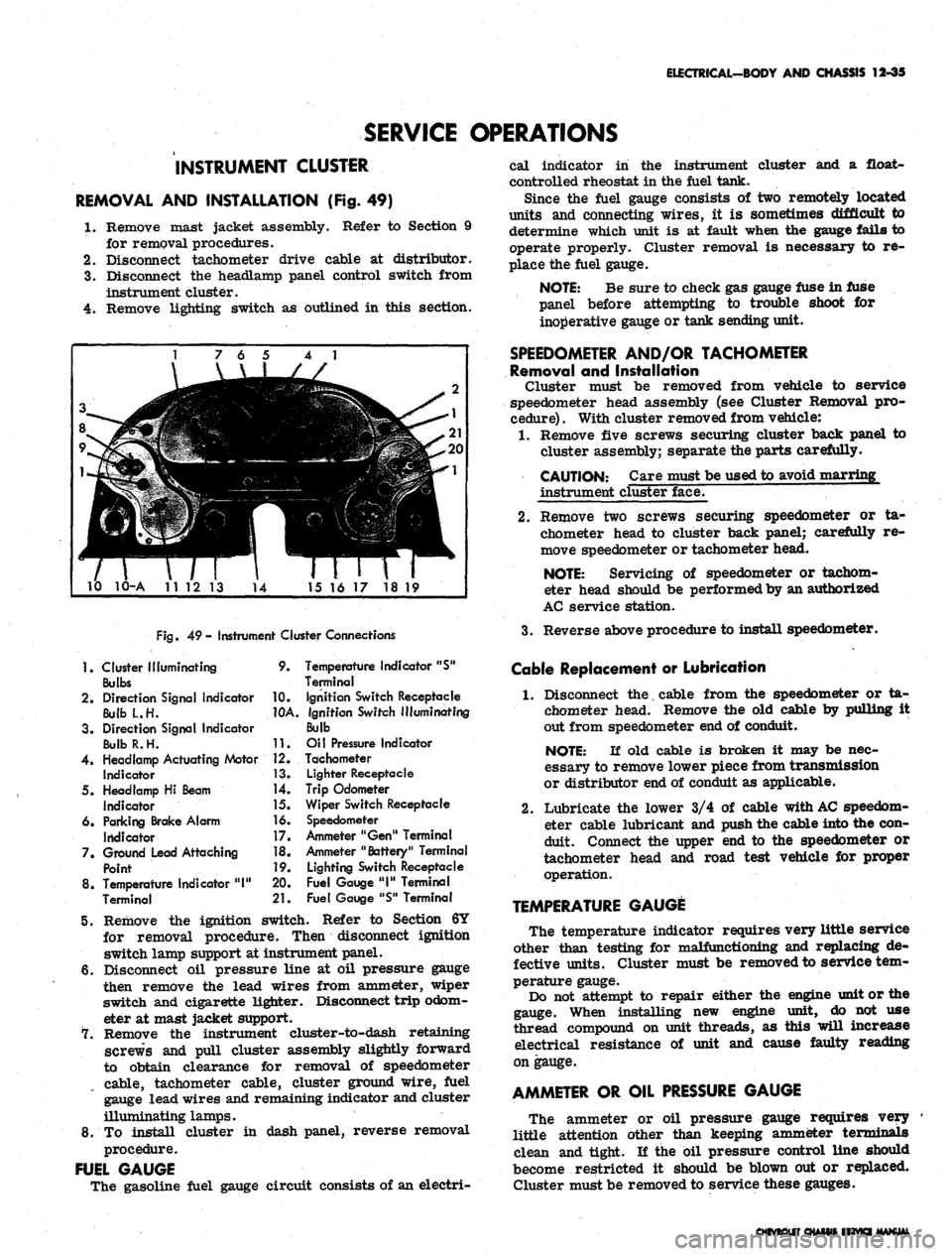
REMOVAL AND INSTALLATION (Fig. 49)
1.
Remove mast jacket assembly. Refer to Section 9
for removal procedures.
2.
Disconnect tachometer drive cable at distributor.
3.
Disconnect the headlamp panel control switch from
instrument cluster.
4.
Remove lighting switch as outlined in this section.
10 10-A 1112 13
14
15 16 17 18 19
Fig.
49- Instrument Cluster Connections
1.
Cluster Illuminating
Bulbs
2.
Direction Signal Indicator
Bulb L.H.
3. Direction Signal Indicator
BulbR.H.
4.
Headlamp Actuating Motor
Indicator
5. Headlamp Hi Beam
Indicator
6. Parking Brake Alarm
Indicator
7. Ground Lead Attaching
Point
8. Temperature Indicator
"1"
Terminal
9.
10.
10A.
11.
12.
13.
14.
]5.
16.
17.
18.
19.
20.
21.
Temperature Indicator "S"
Terminal
Ignition Switch Receptacle
ignition Switch Illuminating
Bulb
Oil Pressure Indicator
Tachometer
Lighter Receptacle
Trip Odometer
Wiper Switch Receptacle
Speedometer
Ammeter "Gen" Terminal
Ammeter "Battery" Terminal
Lighting Switch Receptacle
Fuel Gauge
"1"
Terminal
Fuel Gauge "S" Terminal
5. Remove the ignition switch. Refer to Section 6Y
for removal procedure. Then disconnect ignition
switch lamp support at instrument panel.
6. Disconnect oil pressure line at oil pressure gauge
then remove the lead wires from ammeter, wiper
switch and cigarette lighter. Disconnect trip odom-
eter at mast jacket support.
7. Remove the instrument cluster-to-dash retaining
screws and pull cluster assembly slightly forward
to obtain clearance for removal of speedometer
cable, tachometer cable, cluster ground wire, fuel
gauge lead wires and remaining indicator and cluster
illuminating lamps.
8. To install cluster in dash panel, reverse removal
procedure.
FUEL GAUGE
The gasoline fuel gauge circuit consists of an electri-
cal indicator in the instrument cluster and a float-
controlled rheostat in the fuel tank.
Since the fuel gauge consists of two remotely located
units and connecting wires, it is sometimes difficult to
determine which unit is at fault when the gauge fails to
operate properly. Cluster removal is necessary to re-
place the fuel gauge.
NOTE:
Be sure to check gas gauge fuse in fuse
panel before attempting to trouble shoot for
inoperative gauge or tank sending unit.
SPEEDOMETER AND/OR TACHOMETER
Removal and Installation
Cluster must be removed from vehicle to service
speedometer head assembly (see Cluster Removal pro-
cedure)
.
With cluster removed from vehicle:
1.
Remove five screws securing cluster back panel to
cluster assembly; separate the parts carefully.
CAUTION: Care must be used to avoid marring
instrument cluster face.
2.
Remove two screws securing speedometer or ta-
chometer head to cluster back panel; carefully re-
move speedometer or tachometer head.
NOTE:
Servicing of speedometer or tachom-
eter head should be performed by an authorized
AC service station.
3.
Reverse above procedure to install speedometer.
Cable Replacement or Lubrication
1.
Disconnect the. cable from the speedometer or ta-
chometer head. Remove the old cable by pulling it
out from speedometer end of conduit.
NOTE:
If old cable is broken it may be nec-
essary to remove lower piece from transmission
or distributor end of conduit as applicable.
2.
Lubricate the lower 3/4 of cable with
AC
speedom-
eter cable lubricant and push the cable into the con-
duit. Connect the upper end to the speedometer or
tachometer head and road test vehicle for proper
operation.
TEMPERATURE GAUGE
The temperature indicator requires very little service
other than testing for malfunctioning and replacing de-
fective units. Cluster must be removed to service tem-
perature gauge.
Do not attempt to repair either the engine unit or the
gauge. When installing new engine unit, do not use
thread compound on unit threads, as this will increase
electrical resistance of unit and cause faulty reading
on gauge.
AMMETER OR OIL PRESSURE GAUGE
The ammeter or oil pressure gauge requires very
little attention other than keeping ammeter terminals
clean and tight. If the oil pressure control line should
become restricted it should be blown out or replaced.
Cluster must be removed to service these gauges.
HftVKI MANUAL
Page 548 of 659
ELECTRICAL-BODY
AND
CHASSIS
12-36
CAMARO INSTRUMENTS AND GAUGES
INDEX
Page
General Description
12-36
Service Operations
12-36
Instrument Cluster
. . . 12-36
Instrument Lamps
12-36
Printed Circuit
12-36
Fuel Gauge
12-37
Tachometer
. . 12-37
Seat Separator Instrument Console
12-37
Page
Fuel Gauge
12-37
Ammeter
12-37
Temperature Gauge
12-37
Oil Pressure Gauge
. 12-37
Fuel Warning Unit
12-37
Clock.
... 12-37
Oil Pressure Indicator
12-37
Generator Indicator
12-38
Temperature Indicator
12-38
GENERAL DESCRIPTION
The standard Camaro instrument cluster assembly con-
sists
of two
circular units which house
the
speedometer
and fuel gauge assemblies.
The oil
pressure, left-hand
directional
and
brake warning indicators
are
located
in
the face
of the
speedometer bezel while generator,
tem-
perature
and
right-hand directional indicators are grouped
with
the
fuel gauge unit.
The
high beam indicator
is
located between
the
cluster bezels.
A special instrumentation package
is
available with
the
eight-cylinder engine
and
center floor console combina-
tion.
The
special cluster includes:
a
clock; coolant
temperature,
oil
pressure, fuel
and
ammeter gauges,
mounted forward
on the
seat separator console;
a ta-
chometer
in the
right circular housing
of the
dash
in-
strument cluster; and
a low
fuel level indicator replacing
the
oil
pressure indicator lamp
in the
instrument cluster.
The instruments
and
gauges,
may be
serviced only
after
the
instrument cluster
is
removed from
the
vehicle.
Indicator
and
cluster lamps except
for the
high beam
indicator
may be
replaced without removing
the
cluster
assembly. Partial cluster removal
is
necessary when
replacing
the
high beam indicator due
to its
proximity
to
the upper brace
rod
anchor plate.
The
bulbs
are in-
stalled
in
plastic sockets which lock into
the
cluster
housing and make contact with
the
printed circuit.
A
low
level fuel warning system
is a
special feature
available with
the
floor console gauge pack. This
sys-
tem includes
an
indicator lamp
in the
dash cluster and
a
semi-conductor unit senses
the
change
in
electrical
re-
sistance
of the
fuel system circuitry
as
variations
in
fuel level occur.
The
sensing device
is
replaced
as a
unit
if
found defective.
The brake warning light serves
a
dual purpose.
It
functions
as an
indicator when
the
parking brake
is ap-
plied
and
also
if
there
is a
malfunction (loss
of
hydraulic
pressure)
in the
brake system. Switches which provide
the signal
to
operate
the
light
are
located
at the
parking
brake assembly
and at the
brake master cylinder
in the
hydraulic lines. Service
of the
brake pressure differ-
ential switch unit
is
covered
in
Section
5 of
this manual.
Regular maintenance
is not
required on
the
instrument
cluster
or its
components other than maintaining clean,
tight electrical connections, replacing defective parts
and keeping
the
speedometer properly lubricated.
SERVICE OPERATIONS
INSTRUMENT CLUSTER (Figs.
50
thru
53)
Removal
and
Installation
1.
Disconnect battery ground cable.
2.
Remove mast jacket lower support screws
at toe
pan.
3.
Remove mast jacket upper support bolts
and
allow
steering wheel
to
rest
on
seat cushion.
CAUTION: Both supports must
be
detached
to
prevent distortion
of
mast jacket.
4.
Remove cluster attaching screws from face
of
panel
and partially remove assembly from console opening.
5. Reaching behind cluster assembly, disconnect speed-
ometer cable, speed warning device
(if so
equipped
-
Fig.
51) and
chassis harness connector
at
rear
of
panel.
6. Remove assembly from console opening to
a
suitable
bench area
for
required service operations.
7.
To
install, reverse removal procedure.
INSTRUMENT CLUSTER LAMP REPLACEMENT
1.
Turn bulb holder counterclockwise
and
pull
out to
remove from
the
cluster housing.
2.
Pull bulb straight out
to
remove from socket.
3.
Press replacement bulb inward
to
lock
in
socket.
4.
Insert lamp assembly into housing, with lugs
on
holder entering notches
in
housing,
and
turn clock-
wise
to
lock
in
place.
PRINTED CIRCUIT REPLACEMENT
1.
Remove instrument cluster
as
previously described
in this section.
2.
Remove
all
cluster illuminating and indicator lamps
from housing.
3.
Remove fuel gauge terminal nuts
or
tachometer
re-
taining nuts securing printed circuit
to
housing.
4.
Remove four
hex
head screws retaining printed
cir-
cuit
to the
cluster housing
and
remove circuit from
housing.
5.
To
install, reverse removal procedure.
CAUTION:
The
retaining screws
are
part
of
the grounding circuit
and
must
be
installed
to
provide proper connections
for the
printed
eir-
cuit.
CHEVROLET CHASSIS SERVICE MANUAL
Page 549 of 659
ELECTRICAL-BODY AND CHASSIS 12-37
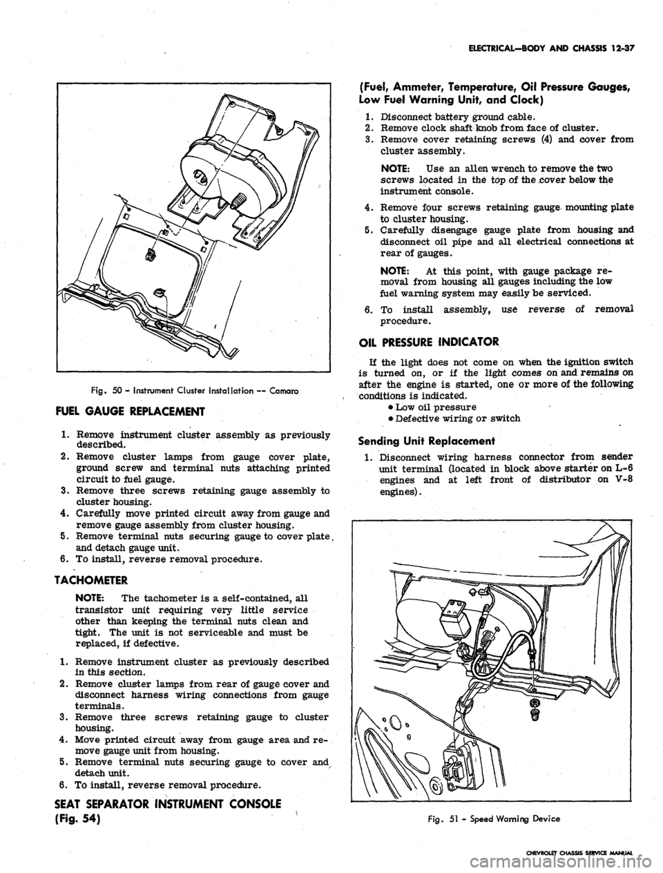
Fig.
50 - Instrument Cluster Installation — Camaro
FUEL GAUGE REPLACEMENT
1.
Remove instrument cluster assembly as previously
described.
2.
Remove cluster lamps from gauge cover plate,
ground screw and terminal nuts attaching printed
circuit to fuel gauge.
3.
Remove three screws retaining gauge assembly to
cluster housing.
4.
Carefully move printed circuit away from gauge and
remove gauge assembly from cluster housing.
5. Remove terminal nuts securing gauge to cover plate,
and detach gauge unit.
6. To install, reverse removal procedure.
TACHOMETER
NOTE:
The tachometer is a self-contained, all
transistor unit requiring very little service
other than keeping the terminal nuts clean and
tight. The unit is not serviceable and must be
replaced, if defective.
1.
Remove instrument cluster as previously described
in this section.
2.
Remove cluster lamps from rear of gauge cover and
disconnect harness wiring connections from gauge
terminals.
3.
Remove three screws retaining gauge to cluster
housing.
4.
Move printed circuit away from gauge area and re-
move gauge unit from housing.
5. Remove terminal nuts securing gauge to cover
detach unit.
6. To install, reverse removal procedure.
SEAT SEPARATOR INSTRUMENT CONSOLE
(Fig.
54)
(Fuel,
Ammeter, Temperature, Oil Pressure Gauges,
Low Fuel Warning Unit, and Clock)
1.
Disconnect battery ground cable.
2.
Remove clock shaft knob from face of cluster.
3.
Remove cover retaining screws (4) and cover from
cluster assembly.
NOTE:
Use an alien wrench to remove the two
screws located in the top of the cover below the
instrument console.
4.
Remove four screws retaining gauge mounting plate
to cluster housing.
5. Carefully disengage gauge plate from housing and
disconnect oil pipe and all electrical connections at
rear of gauges.
NOTE:
At this point, with gauge package re-
moval from housing all gauges including the low
fuel warning system may easily be serviced.
6. To install assembly, use reverse of removal
procedure.
OIL PRESSURE INDICATOR
If the light does not come on when the ignition switch
is turned on, or if the light comes on and remains on
after the engine is started, one or more of the following
conditions is indicated.
• Low oil pressure
• Defective wiring or switch
Sending Unit Replacement
1.
Disconnect wiring harness connector from sender
unit terminal (located in block above starter on L-6
engines and at left front of distributor on V-8
engines).
Fig.
51 - Speed Warning Device
CHEVROLET CHASSIS SERVICE MANUAL
Page 555 of 659
ELECTRICAL-BODY AND CHASSIS 12-43
23.
Install
MCtT
ring over steering shaft using snap ring
installer J-22659 (refer to Section 9).
NOTE: Be sure retaining ring is completely
seated into groove.
24.
Install dial pointer on Chevrolet and Chevelle models
equipped with automatic transmission (if applicable).
25.
Install dial indicator and lamp assembly on Camaro
and Chevy n models equipped with automatic
transmission.
26.
Install mast jacket lower trim covers (if applicable).
27.
Install hazard warning knob and turn signal lever.
28.
Install shift lever.
29.
Install steering wheel.
30.
Install multiple connector to switch wiring using old
harness for wire color guide and connect to body
harness connector.
31.
Connect battery ground cable and check operation of
assembly.
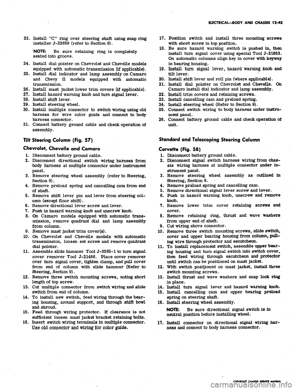
Tilt Steering Column (Fig. 57)
Chevrolet, Chevelle and Camaro
1.
Disconnect battery ground cable.
2.
Disconnect directional switch wiring harness from
body harness at multiple connector under instrument
panel.
3.
Remove steering wheel assembly (refer to Steering,
Section 9).
4.
Remove preload spring and cancelling cam from end
of shaft.
5.
Remove shift lever pin and lever from steering col-
umn (except floor shift).
6. Remove directional le*ver screw and lever.
7.
Push in hazard warning knob and unscrew knob.
8. On Camaro models equipped with automatic trans-
mission, remove quadrant dial and lamp assembly
from column.
9. Remove mast jacket trim cover
(s).
10.
On Chevrolet and Chevelle models with automatic
transmission, loosen set screw and remove quadrant
dial pointer.
11.
Assemble slide hammer Tool J-6585-1 to turn signal
cover remover Tool J-21486. Place cover remover
over turn signal cover, tighten clamp, and pull cover
from end of column with slide hammer (Refer to
Steering, Section 9).
12.
Remove three switch mounting screws, noting short
length of top screw.
13.
Cut multiple connector from switch wiring and slide
switch from end of column.
14.
To install new switch, feed wiring through the bear-
ing housing, around support, and through shift bowl
and shroud.
15.
Feed through wiring protector. If clearance is not
sufficient loosen mast jacket bracket retaining bolts.
16.
Insert switch wiring terminals in multiple connector.
Use old connector
and
wiring for color guide.
17.
Position switch and install three mounting screws
with short screw in top position.
18.
Be sure hazard warning switch is pushed in, then
install turn signal cover using special Tool J-21853.
On automatic columns align key in cover with keyway
in bearing housing.
19.
Install turn signal lever, hazard warning knob and
tilt lever.
20.
Install shift lever and roll pin (where applicable).
21.
Install dial pointer on Chevrolet and Chevelle. On
Camaro install dial indicator and lamp assembly.
22.
Install trim covers and retaining screws.
23.
Install cancelling cam and preload spring.
24.
Install steering wheel (Refer to Section 9).
25.
Connect switch wiring to body harness under instru-
ment panel.
26.
Connect battery ground cable and check operation of
unit.
Standard and Telescoping Steering Column
Corvette (Fig. 58)
1.
Disconnect battery ground cable.
2.
Disconnect signal switch harness wiring from chas-
sis wiring harness at multiple connector under in-
strument panel.
3.
Remove steering wheel assembly as outlined in
Steering, Section 9.
4.
Remove preload spring and cancelling cam.
5.
Remove directional signal lever screw and lever.
6. Push in hazard warning knob, unscrew and remove
knob.
7.
Remove lower trim cover retaining screws and
cover.
8. Remove retaining ring, thrust and wave washers
from upper end of shaft.
9. Cut wiring above connector.
10.
Remove three switch mounting screws, slide switch,
cover and upper bearing housing from column, pull-
ing wire through protector and escutcheon.
11.
To install replacement switch, assemble upper bear-
ing housing and turn signal switch into switch cover,
then feed wiring through escutcheon and protector
until switch can be positioned on mast jacket.
12.
With switch positioned on mast jacket, install three
switch mounting screws.
13.
Install thrust and wave washers and snap lock ring
in place.
14.
Install turn signal lever and hazard warning knob.
15.
Install cancelling cam and upper bearing preload
spring on steering shaft.
16.
Install steering wheel assembly.
NOTE:
Be sure directional signal switch is in
neutral position before installing wheel.
17.
Install connector on directional signal wiring har-
ness and connect to body harness connector.
CHEVROLET CHASSIS SERVICE
Page 652 of 659
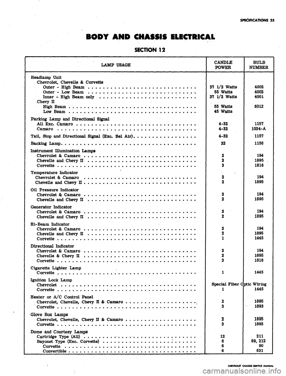
SPECIFICATIONS 25
BODY AND CHASSIS ELECTRICAL
SECTION
12
LAMP USAGE
CANDLE
POWER
BULB
NUMBER
Headlamp Unit
Chevrolet, Chevelle & Corvette
Outer - High Beam
Outer - Low Beam
Inner -• High Beam only
Chevy H
High Beam . .
Low Beam
Parking Lamp and Directional Signal
All Exc. Camaro
Camaro
Tail, Stop and Directional Signal (Exc. Bel Air)
Backing Lamp ••...,
Instrument Illumination Lamps
Chevrolet & Camaro ,
Chevelle and Chevy n
Corvette
Temperature Indicator
Chevrolet & Camaro
Chevelle and Chevy II .............
Oil Pressure Indicator
Chevrolet & Camaro .............
Chevelle and Chevy II
Generator Indicator
Chevrolet & Camaro .
Chevelle and Chevy n ,
Hi-Beam Indicator
Chevrolet & Camaro <
Chevelle and Chevy II
Corvette , . • . ,
Directional Indicator
Chevrolet & Camaro
Chevelle & Chevy II . .
Corvette . .
Cigarette Lighter Lamp
Corvette .
Ignition Lock Lamp
Chevrolet . . .
Corvette . . .
Heater or A/C Control Panel
Chevrolet, Chevelle, Chevy n & Camaro . . .
Corvette . . .
Glove Box Lamps
Chevrolet, Chevelle, Chevy n & Camaro . . .
Corvette . . . . .
Dome and Courtesy Lamps
Cartridge Type (AU)
Bayonet Type (Exc. Corvette) . . .
Corvette ,
Convertible . .
37 1/2 Watts
55 Watts
37 1/2 Watts
55 Watts
45 Watts
4-32
4-32
4-32
Special Fiber
1
2
3
2
3
12
6
6
6
Optic
4002
4002
4001
6012
1157
1034-A
1157
1156
194
1895
.
1816
194
1895
194
1895
194
1895
194
1895
1445
194
1895
1816
1445
Wiring
1445
1895
1893
1895
1893
211
89,
212
90
631
CHEVROLET CHASSIS SERVICE MANUAL