fuse diagram CHEVROLET CAMARO 1967 1.G Chassis Workshop Manual
[x] Cancel search | Manufacturer: CHEVROLET, Model Year: 1967, Model line: CAMARO, Model: CHEVROLET CAMARO 1967 1.GPages: 659, PDF Size: 114.24 MB
Page 59 of 659
HEATER AND AIR CONDITIONING 1A-36
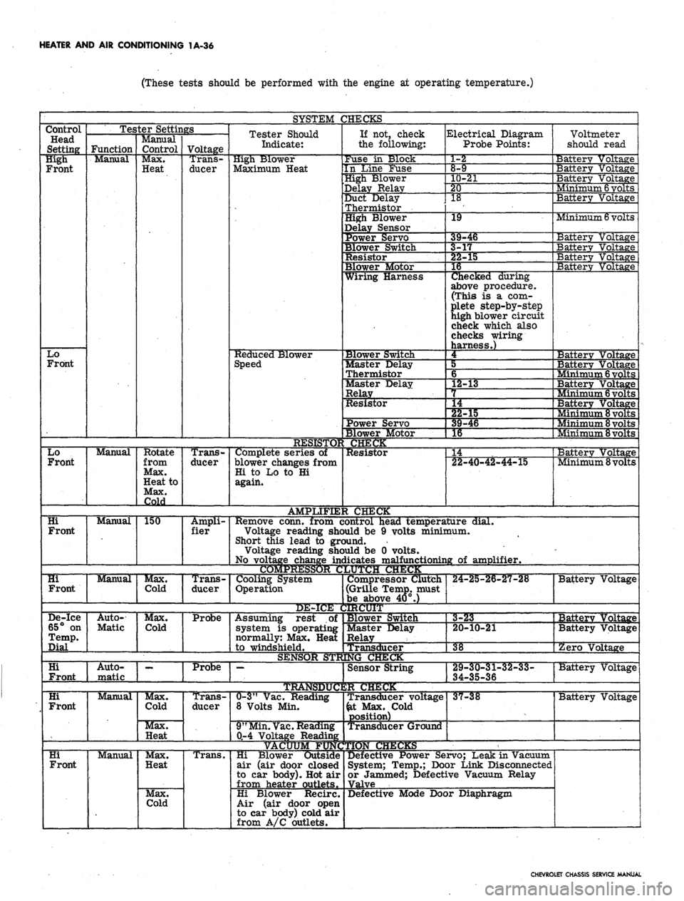
(These tests should be performed with the engine at operating temperature.)
SYSTEM CHECKS
Control
Head
Setting
High
Front
Lo
Front
Lo
Front
Hi
Front
Hi
Front
Tester Settings
Function
Manual
Manual
Manual
Manual
De-ice
65° on
Temp.
Dial
Hi
Front
Hi
Front
Hi
Front
Auto-
Matic
1 1
Auto-
matic
Manual
Manual
Manual
Control
Max.
Heat
Rotate
from
Max.
Heat to
Max.
Cold
150
Max.
Cold
Max.
Cold
Max.
Cold
Max.
Heat
Max.
Heat
Max.
Cold
Voltage
Trans-
ducer
Trans-
ducer
Ampli-
fier
Trans-
ducer
Probe
Probe
Trans-
ducer
Trans.
Tester Should
Indicate:
High Blower
Maximum Heat
Reduced Blower
Speed
Complete series of
blower changes from
Hi to Lo to Hi
again.
AMPLIFIE:
Remove conn, from c
Voltage reading she
Short this lead to grc
Voltage reading she
No voltage change in<
COMPRESSOR C
Cooling System
Operation
DE-ICE i
Assuming rest of
system is operating
normally: Max. Heat
1
to windshield.
SENSOR STR
•—
TRAtfSDtfC
0-3"
Vac. Reading
8 Volts Min.
9"
Min.
Vac.
Reading
0-4 Voltage Reading
If not, check
the following:
Fuse in Slock
In Line Fuse
High Blower
Delay Relay
Duct Delay
Thermistor
High Blower
Delay Sensor
Power Servo
Blower Switch
Resistor
Blower Motor
Wiring Harness
Blower Switch
Master Delay
Thermistor
Master Delay
Relay
Resistor
Power Servo
Blower Motor
CHECK
Resistor
I CHECK
Electrical Diagram
Probe Points:
1-2
8-9
10-21
20
18
19
*
9-46
-r
^2-3
15
16
Checked during
above procedure.
(This is a com-
plete step-by-step
high blower circuit
check which also
checks wiring
harness.)
4
5
6
L2-13
L4
""§2-15
39-46
1
16 1
14
22-40-42-44-15
.ontrol head temperature dial.
>uld be 9 volts minimum,
jund.
>uld be 0 volts,
iicates malfunctioning of amplifier.
JUTCJH CHUCK
Compressor Clutch
(Grille Temp, must
be above 40°.)
IRCUIT
Blower Switch
Master Delay
Relay
Transd
NGCl
ucer
Sensor String
2R CHECK
Transducer voltage
&t Max. Cold
position)
Transducer Ground
Hi Blower Outside
air (air door closed
to car body). Hot air
from heater outlets.
Hi Blower Recirc.
Air (air door open
to car body) cold air
from A/C outlets.
24-25-26-27-28
Voltmete
should re
ad
Battery Voltage
Battery Voltage
Battery Voltage
. Vtinimum
6
volts
Battery Voltage
Minimum
6
volts
Battery Vo]
Batterv Vo]
Ltage
Ltage
Battery Voltage
Batterv Voltage
3a
Bai
:terv Vo
tterv Vo
tage
tage
Minimum
6
volts
Batterv Voltage
Minimum
6
volts
Battery Voltage
Minimum
8
volts
Minimum 8 volts
Minimum 8 volts
Batterv Voltage
Minimum 8 volts
1 III • II »ll. —..• —•— . !!•• 1
Battery Voltage
3-23
20-10-21
38
29-30-31-32-33-
34-35-36
37-38
Defective Power Servo; Leak in Vacuum
System; Temp.; Door Link Disconnected
or Jammed; Defective Vacuum Relay
Valve
Defective Mode Door Diaphragm
Batterv Voltage
Battery Voltage
Zero Voltage
Battery Voltage
Battery Voltage
CHEVROLET CHASSIS SERVICE MANUAL
Page 63 of 659
HEATER AND AIR CONDITIONING 1A-40
THERAAAL VACUUM
VALVE
TO ENGINE
VACUUM
SOURCE
VACUUM STORAGE
TANK
OUTSIDE AIR
DIAPHRAGM
MODE
DIAPHRAGM
VACUUM
RELAY
BLACK
DEFOG-DEICE
DIAPHRAGM
GREEN
BLACKj ||
|
BROWN
CONTROL
VALVE
Fig.
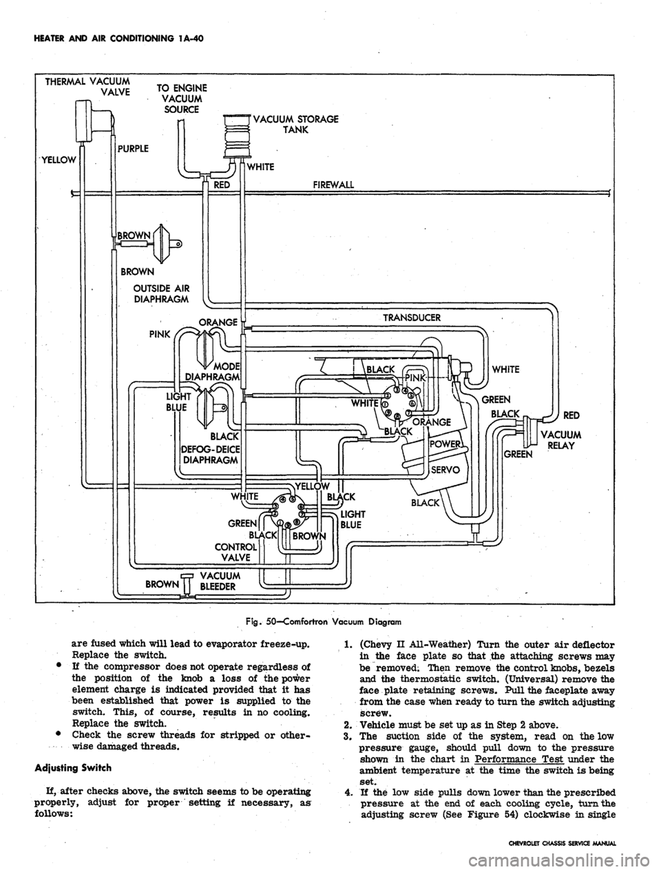
50—Comfortron Vacuum Diagram
are fused which will lead to evaporator freeze-up.
Replace the switch.
• If the compressor does not operate regardless of
the position of the knob a loss of the power
element charge is indicated provided that it has
been established that power is supplied to the
switch. This, of course, results in no cooling.
Replace the switch.
• Check the screw threads for stripped or other-
wise damaged threads.
Adjusting Switch
H, after checks above, the switch seems to be operating
properly,
follows:
adjust for proper setting if necessary, as
1.
(Chevy II All-Weather) Turn the outer air deflector
in the face plate so that the attaching screws may
be removed; Then remove the control knobs, bezels
and the thermostatic switch. (Universal) remove the
face plate retaining screws. Pull the faceplate away
from the case when ready to turn the switch adjusting
screw.
2.
Vehicle must be set up as in Step 2 above.
3.
The suction side of the system, read on the low
pressure gauge, should pull down to the pressure
shown in the chart in Performance Test under the
ambient temperature at the time the switch is being
set.
4.
If the low side pulls down lower than the prescribed
pressure at the end of each cooling cycle, turn the
adjusting screw (See Figure 54) clockwise in single
CHEVROLET CHASSIS SERVICE MANUAL
Page 103 of 659

HEATER
AND AIR
CONDITIONING
1A-80
EVAPORATOR ASM.
Blower
Motor
INSIDE VALVE
(Normally closed
-spring held)
PLENUM VALVE
(Normally open
-spring held)
Actuator
(Vacuum
operated)
Inside car air (Recirc*
CONTROL ASM
TEMP CONTROL LEVER
•(Operates temp valve
cable
&
equipment in
hart shown below)
Temp valve
begins to
16DG
Fuse (In-line^
COMPRESSOR
Clutch Coil DASH-
PANEL
•Fan Speed Selector Switch
Switch
lever
position
Off
Low
"HeST
High
Contacts
B to
None
BtoL
B to L b U
BtoL&H
Fan
speed
Low
Low
Med
High
Resistance
in series with
Bio Motor
Rl
Rl
RlR2)/(Rl+R2)
None
•Blower switch contacts must be closed
before fan switch will be operable.
-To battery positive
(-0 terminal
•
Horn relay
terminal"
"Batf
To vacuum
tank
EXTENSION
WIRE
ASM
(Normally closed
contacts-*vac
operated)
7
*- Fan speed switch
(See chart at left)
•/-Wire is
\ part of
I inst panel
harness
Legend:
— Production wiring
————
Wire Is part of equip.
•mmmmmmmmmmmmmm*
AIT
Conditioning
WTg*
Temp
Control
Lever
Position
OFF
VENT
COLD
a.A.)
COLD
(O.A.)
HOT
Blower
(Master)
switch
contacts
Open
Closed
Closed
Closed
Closed
Vac switch
connects
vac source
to hose #
#2
&
#3
#2
#3
None
#2
Compressor
switch
contacts^
Open
Open
Closed
Closed
Open
Blower
intake air
Outside car air
intake used
Inside car air
recir culated
Outside car air
intake used
Outside car air
intake used
Fig.
116—Camaro—Four-Season Wiring Diagram
CHEVROLET CHASSIS SERVICE
Page 104 of 659
HEATER AND AIR CONDITIONING 1A-81
HORN RELAY
r
CONN.-
14 BROWN
(TO FUSE
PANEL)
BATTERY
1
—I ^ COMPR
ESSOR
DASH y
V-^ PANEL \
GROMMET—%
1 \
_ J~ ") "^
>14 BLACK/RED STRIPE-
FUSE .20 AMP.
•WIRE ASM. BLOWER-
MOTOR
14 BLACK 1
IGNITION SWITCH1
(ACCESSORY
TERMINAL)
CONTROL SWITCH
-RESISTOR
CONN.
•14 TAN
•16 BLACK
LIGHT BLUE STRIPE
•THERMOSTAT CONTROL
EVAPORATOR & BLOWER ASM.
Fig.
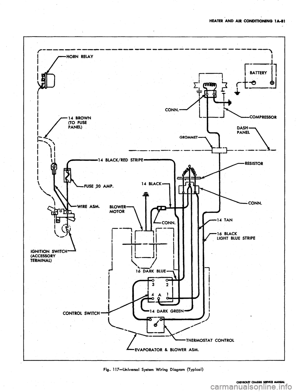
117—Universal System Wiring Diagram (Typical)
CHEVROLET CHASSI
Page 105 of 659
HEATER AND AIR CONDITIONING 1A-82
•BATTERY
(POS)
CABLE
NOTE
When
control
switch*
is !TOFF"
&
Air
Cond
is
"ON"
(Control
knob
pulled
but) the
blower
fan'will
run at low
speed.
CONTROL
SWITCH
CONNECTIONS
OFF
LOW
MED
HIGH
B
TO
NONE
B
TO L
BTOL&M
B
TO L
&
H
COMPRESSOR
GROUND
WIRE
ASM
BATTERY
(NEGATIVE)
CABLE
COMPRESSOR
ASM
DASHPAJSTEL
GROMMET
16DG
CONTROL
SWITCH
RESISTOR
ASM
14LBL
14BRN
CLUTCH
COIL
EXTENSION
WIRE
ASM
-14BRN--N
JUNC
BLOCKi
OSTATIC
SWITCH
CONTACTS
NORMALLY
CLOSED
STARTING
MOTOR
SOLENOID
BLOWER
MOTOR
AIR
COND
CONTROL
(PUSH-PULL)
KNOB
DOOR
SWITCH
(PUSH
BUTTON
NORMALLY
CLOSED)
RELAY
ASM
HORN
RELAY
DIVERTER
DOOR CABLE
FUSE
PANEL
EVAPORATOR
ASM
IGNITION SWITCH-
ACCESSORY TERMINAL)
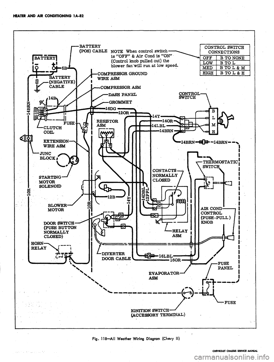
Fig. 118—All Weather Wiring Diagram (Chevy II)
CHEVROLET CHASSIS SERVICE MANUAL
Page 334 of 659
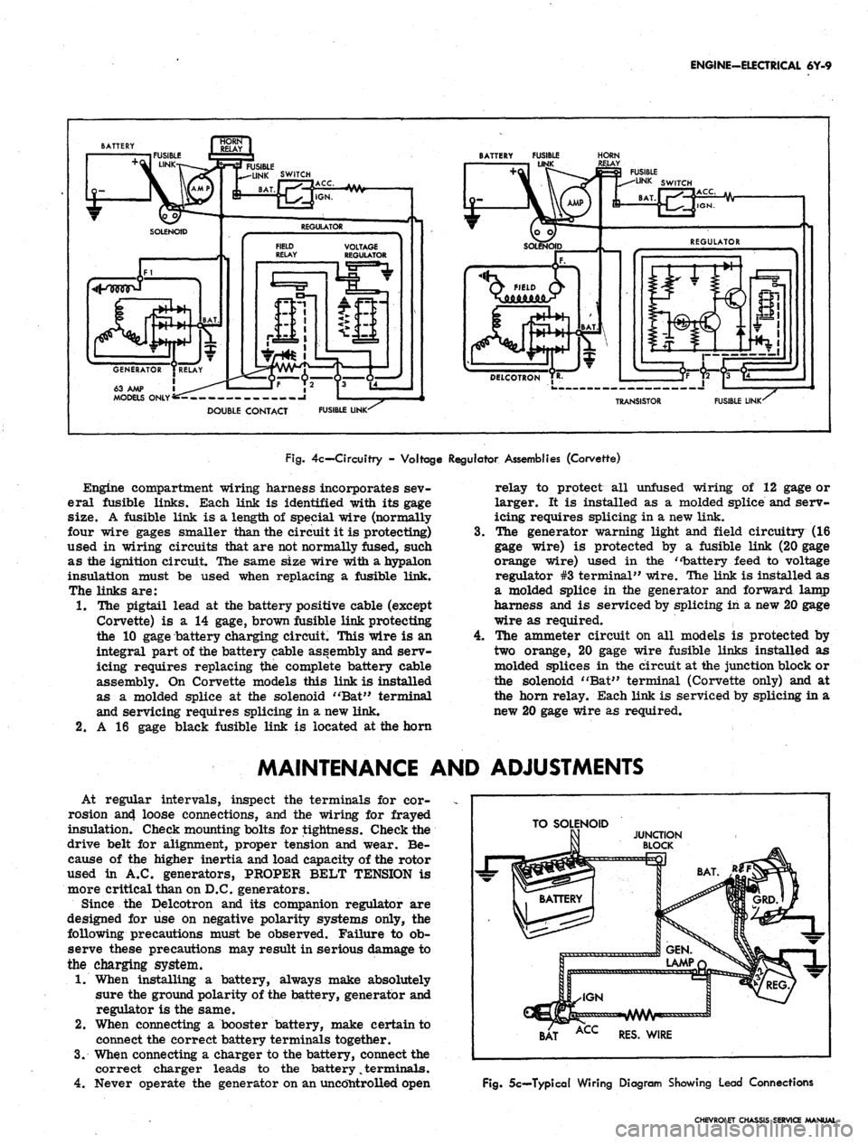
ENGINE-ELECTRICAL 6Y-9
63 AMP 1
MODELS ONLY'
BATTERY FUSIBLE
LINK
HORN
FUSIBLE LINK'
TRANSISTOR
FUSIBLE LINK'
Fig.
4c— Circuitry - Voltage Regulator Assemblies (Corvette)
Engine compartment wiring harness incorporates sev-
eral fusible links. Each link is identified with its gage
size. A fusible link is a length of special wire (normally
four wire gages smaller than the circuit it is protecting)
used in wiring circuits that are not normally fused, such
as the ignition circuit. The same size wire with a hypalon
insulation must be used when replacing a fusible link.
The links are:
1.
The pigtail lead at the battery positive cable (except
Corvette) is a 14 gage, brown fusible link protecting
the 10 gage battery charging circuit. This wire is an
integral part of the battery cable assembly and serv-
icing requires replacing the complete battery cable
assembly. On Corvette models this link is installed
as a molded splice at the solenoid "Bat" terminal
and servicing requires splicing in a new link.
2.
A 16 gage black fusible link is located at the horn
4.
relay to protect all unfused wiring of 12 gage or
larger. It is installed as a molded splice and serv-
icing requires splicing in a new link.
The generator warning light and field circuitry (16
gage wire) is protected by a fusible link (20 gage
orange wire) used in the "battery feed to voltage
regulator #3 terminal" wire. The link is installed as
a molded splice in the generator and forward lamp
harness and is serviced by splicing in a new 20 gage
wire as required.
The ammeter circuit on all models is protected by
two orange, 20 gage wire fusible links installed as
molded splices in the circuit at the junction block or
the solenoid "Bat" terminal (Corvette only) and at
the horn relay. Each link is serviced by splicing in a
new 20 gage wire as required.
MAINTENANCE AND ADJUSTMENTS
At regular intervals, inspect the terminals for cor-
rosion an4 loose connections, and the wiring for frayed
insulation. Check mounting bolts for tightness. Check the
drive belt for alignment, proper tension and wear. Be-
cause of the higher inertia and load capacity of the rotor
used in A.C. generators, PROPER BELT TENSION is
more critical than on D.C. generators.
Since the Delcotron and its companion regulator are
designed for use on negative polarity systems only, the
following precautions must be observed. Failure to ob-
serve these precautions may result in serious damage to
the charging system.
1.
When installing a battery, always make absolutely
sure the ground polarity of the battery, generator and
regulator is the same.
2.
When connecting a booster battery, make certain to
connect the correct battery terminals together.
3.
When connecting a charger to the battery, connect the
correct charger leads to the battery
%
terminals.
4.
Never operate the generator on an uncontrolled open
TO SOLENOID
BAT ACC RES. WIRE
Fig.
5c—Typical Wiring Diagram Showing Lead Connections
CHEVROLET CHASSIS SERVICE MANUAL
Page 372 of 659
CLUTCH AND TRANSMISSIONS 7-13
PULL-IN
WINDING
li
HOLD-IN
WINDING
Fig.
4B -
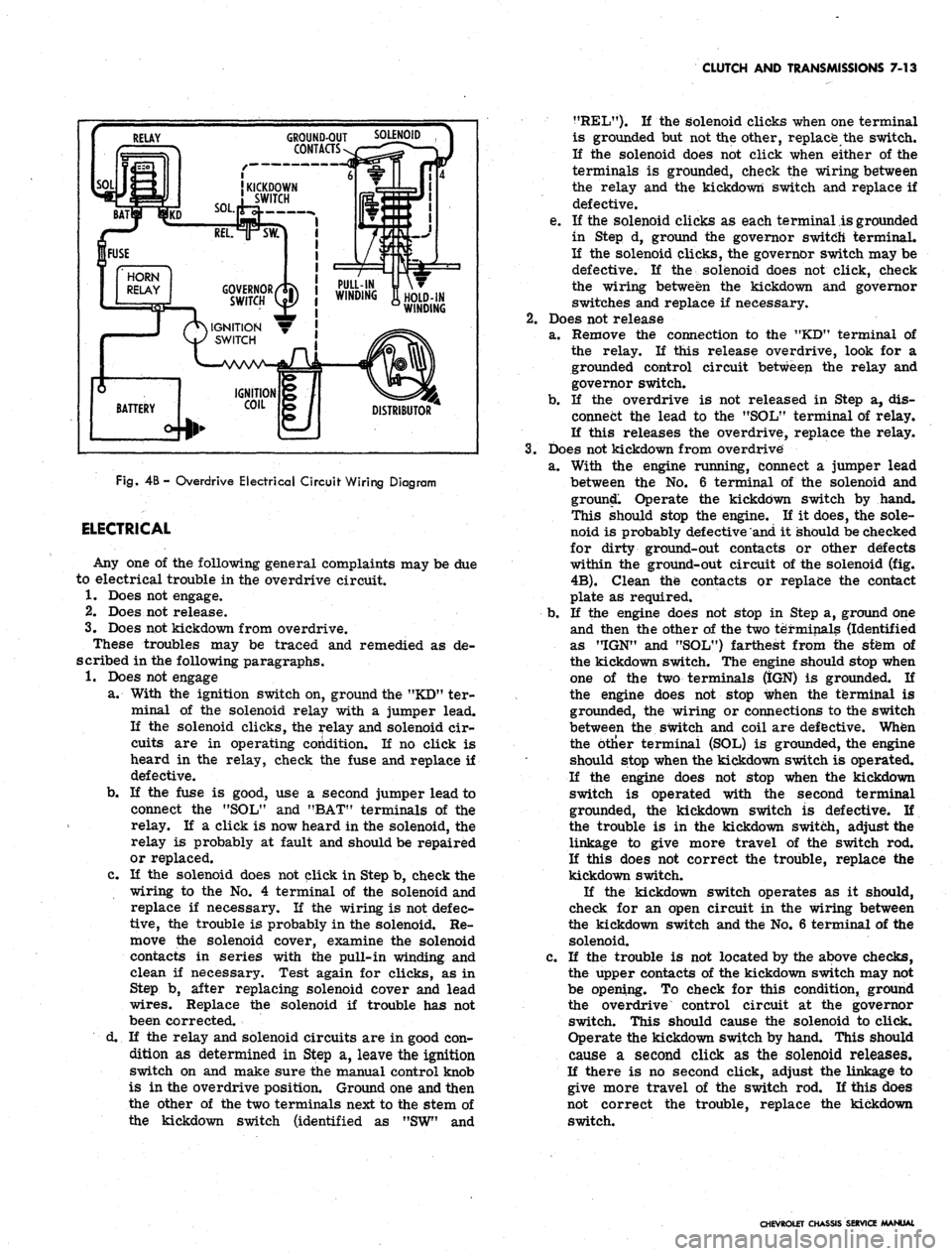
Overdrive Electrical Circuit Wiring Diagram
ELECTRICAL
Any one of the following general complaints may be due
to electrical trouble in the overdrive circuit.
1.
Does not engage.
2.
Does not release.
3.
Does not kickdown from overdrive.
These troubles may be traced and remedied as de-
scribed in the following paragraphs.
1.
Does not engage
a. With the ignition switch on, ground the "KD" ter-
minal of the solenoid relay with a jumper lead.
If the solenoid clicks, the relay and solenoid cir-
cuits are in operating condition. If no click is
heard in the relay, check the fuse and replace if
defective.
b.
If the fuse is good, use a second jumper lead to
connect the "SOL" and "BAT" terminals of the
relay. If a click is now heard in the solenoid, the
relay is probably at fault and should be repaired
or replaced.
c. If the solenoid does not click in Step b, check the
wiring to the No. 4 terminal of the solenoid and
replace if necessary. If the wiring is not defec-
tive,
the trouble is probably in the solenoid. Re-
move the solenoid cover, examine the solenoid
contacts in series with the pull-in winding and
clean if necessary. Test again for clicks, as in
Step b, after replacing solenoid cover and lead
wires.
Replace the solenoid if trouble has not
been corrected.
d. If the relay and solenoid circuits are in good con-
dition as determined in Step a, leave the ignition
switch on and make sure the manual control knob
is in the overdrive position. Ground one and then
the other of the two terminals next to the stem of
the kickdown switch (identified as "SW" and
?fREL"). K the solenoid clicks when one terminal
is grounded but not the other, replace the switch.
If the solenoid does not click when either of the
terminals is grounded, check the wiring between
the relay and the kickdown switch and replace if
defective.
e. If the solenoid clicks as each terminal is grounded
in Step d, ground the governor switch terminal.
If the solenoid clicks, the governor switch may be
defective. If the solenoid does not click, check
the wiring between the kickdown and governor
switches and replace if necessary.
2.
Does not release
a. Remove the connection to the "KD" terminal of
the relay. If this release overdrive, look for a
grounded control circuit between the relay and
governor switch.
b.
If the overdrive is not released in Step a, dis-
connect the lead to the "SOL" terminal of relay.
If this releases the overdrive, replace the relay.
3.
Does not kickdown from overdrive
a. With the engine running, connect a jumper lead
between the No. 6 terminal of the solenoid and
ground. Operate the kickdown switch by hand.
This should stop the engine. If it does, the sole-
noid is probably defective and it should be checked
for dirty ground-out contacts or other defects
within the ground-out circuit of the solenoid (fig.
4B).
Clean the contacts or replace the contact
plate as required.
b.
If the engine does not stop in Step a, ground one
and then the other of the two terminals (Identified
as "IGN" and "SOL") farthest from the sfem of
the kickdown switch. The engine should stop when
one of the two terminals (IGN) is grounded. If
the engine does not stop when the terminal is
grounded, the wiring or connections to the switch
between the switch and coil are defective. When
the btlier terminal (SOL) is grounded, the engine
should stop when the kickdown switch is operated.
If the engine does not stop when the kickdown
switch is operated with the second terminal
grounded, the kickdown switch is defective. If
the trouble is in the kickdown switch, adjust the
linkage to give more travel of the switch rod.
If this does not correct the trouble, replace the
kickdown switch.
If the kickdown switch operates as it should,
check for an open circuit in the wiring between
the kickdown switch and the No. 6 terminal of the
solenoid.
c. If the trouble is not located by the above checks,
the upper contacts of the kickdown switch may not
be opening. To check for this condition, ground
the overdrive control circuit at the governor
switch. This should cause the solenoid to click.
Operate the kickdown switch by hand. This should
cause a second click as the solenoid releases.
If there is no second click, adjust the linkage to
give more travel of the switch rod. If this does
not correct the trouble, replace the kickdown
switch.
CHEVROLET CHASSIS SERVICE MANUAL
Page 513 of 659
SECTION 12
ELECTRICAL-BODY AND CHASSIS
CONTENTS
OF
THIS
SECTION
Page
Page
System 12-1
Instruments and Gauges 12-21
Directional Signal 12r40
Windshield Wipers and Washers 12-44
Wiring Diagrams 12-56
Special Tools 12-60
LIGHTING SYSTEM
INDEX
Page
General Description
!2-i
Maintenance and Adjustments
•.................. 12-2
Headlamp Adjustment......................
12-3
Headlamp Panel Travel Adjustment.
12-5
Service Operations.
. . .. 12-5
Front Lighting
12-5
Headlamp
. 12_5
Parking Lamp
12-5
Fender Lamp
. 12_^
Headlamp Panel
12-8
Headlamp Panel Motor
^2-9
Rear Lighting
l2-10
Tail, Stop and Directional Lamps
12-10
Page
Backing Lamps
12-14
License Plate Lamp
12-14
Automatic Transmission Quadrant Lamp
12-14
Seat Separator Console Lamps
. 12-15
Lighting Switch
. . 12-15
Wiper Switch.
12-15
Stoplight Switch
12-15
Dimmer Switch
12-15
Backing Lamp Switches
12-15
Neutral Safety Switches
12-17
Parking Brake Alarm Switch
................. 12-19
Instrument Panel Compartment Lamp/Switch
12-19
Cirgarette Lighter
12-19
GENERAL DESCRIPTION
.
The lighting system includes: the main lighting switch,
stop light, dimmer, and backing lamp switches, head-
lamps, parking lamps, stop, tail and directional lamps,
instrument illumination and indicator lamps, and the
necessary wiring to complete the various circuits. A
fuse panel provides convenient power take offs and fuse
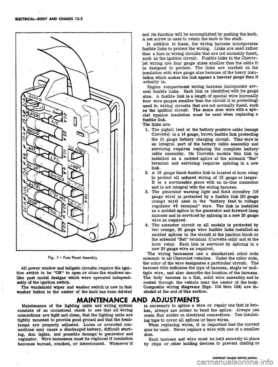
clips for the appropriate circuits (fig. 1).
Chevrolet and Chevelle headlamp installation is all
new in that the headlamps are located in the radiator
support with adjusting screws and springs. Eliminating
the need for having separate headlamp housings. Chev-
rolet and Chevelle headlamp retainers and springs are
interchangeable.
Chevy n headlamp housings are new because of revised
front end styling and Corvette front end lighting is basi-
cally carryover.
Front fender lamps have been added as an option for
Chevrolet models and as standard equipment on Caprice
series.
Camaro models use single headlamps and the Rally
Sport model headlamps are covered by a retractable
section of the grille when lamps are not used. The sec-
tion of the grille covering the headlamps folds back when
lights are required; the headlamps are stationary. The
covering is retracted by a small electric motor mounted
to the headlamp housing. The headlamps are automat-
ically uncovered when the headlight switch is pulled "ON"
for illumination. If at any time the electrical circuit
becomes inoperative, the lamps can be uncovered manu-
ally. The ignition switch must be
"ON"
in order to close
the headlamp doors.
Parking lamp for Chevelle and Chevrolet models are
new due to revised front end sheet metal and bumper
styling. Parking lamps are located in the bumper on
Chevrolet, Chevelle and Chevy n models
Camaro parking lamps are located in the radiator
grille except for the Rally Sport models on which the
parking lamps are in the valance panel. For styling
reasons, the lens is white and an amber glass bulb is
used. All Camaro parking lamps require a separate
ground wire to assure a good ground contact because of
the plastic grille and painted contact surfaces.
The Chevrolet tail, stop, and directional lamps are in
one housing with a three section lens design on Impala
and Caprice sedans. The center lens for Impala series
is the back-up lamp. The center lens on the Caprice is
a tail lamp with the back-up lamps being located in the
rear bumper. Chevrolet station wagons have three indi-
vidual housings with three lenses, the center lamp being
the back-up. Biscayne and Bel-Air sedans have a single
housing and lens for tail, stop, and directional lamp with
a similarly constructed back-up lamp inboard and adja-
cent to it.
Chevelle tail, stop, and directional lamps are a single
lens design that follows through with the rear fender
styling. The back-up lamp is located in r.ear bumper.
Camaro models except Rally Sport have tail lamps
with integral back-up lamps mounted inboard of the rear
fenders between the trunk opening and bumper. The
Rally Sport model has dual tail lamps in the rear housing
and valance mounted back-up lamps.
Corvette, Chevy n, and Corvair tail and directional
signal lights are carryover. The Corvette has new back-
up lamps center mounted above the license plate opening.
CHEVROLET CHASSIS SERVICE
Page 514 of 659
ELECTRICAL-BODY AND CHASSIS 12-2
FJg.
1 - Fuse Panel Assembly
All power window and tailgate circuits require the igni-
tion switch to be "ON" to open or close the windows un-
like past model designs which were operated independ-
ently of the ignition switch.
The windshield wiper and washer switch is new in that
washer button in the center of the knob has been deleted
and its function will be accomplished by pushing the knob.
A set screw is used to retain the knob to the shaft.
In addition to fuses, the wiring harness incorporates
fusible links to protect the wiring. Links are used rather
than a fuse in wiring circuits that are not normally fused,
such as the ignition circuit. Fusible links in the Chevro-
let wiring are four gauge sizes smaller than the cable it
is designed to protect. The links are marked on the
insulation with wire gauge size because of the heavy insu-
lation which makes the link appear a heavier gauge than it
actually is.
Engine compartment wiring harness incorporate sev-
eral fusible links. Each link is identified with its gauge
size.
A fusible link is a length of special wire (normally
four wire gauges smaller than the circuit it is protecting)
used in wiring circuits that are not normally fused, such
as the ignition circuit. The same size wire with a spe-
cial hypalon insulation must be used when replacing a
fusible link.
The links are:
1.
The pigtail lead at the battery positive cable (except
Corvette) is a 14 gauge, brown fusible link protecting
the 10 gange battery charging circuit. This wire is
an integral part of the battery cable assembly and
servicing requires replacing the complete battery
cable assembly. On Corvette models this link is
installed as a molded splice at the solenoid "Bat"
terminal and servicing requires splicing in a new
link.
2.
A 16 gauge black fusible link is located at horn relay
to protect all unfused wiring of 12 gauge or larger.
It is a serviceable piece with an in-line connector
and is not integral with the wiring harness.
3.
The generator warning light and field circuitry (16
gauge wire) is protected by a fusible link (20 gauge
orange wire) used in the "battery feed to voltage
regulator #3 terminal" wire. The link is installed
as a molded splice in the generator and forward lamp
harness and is serviced by splicing in a new 20 gauge
wire as required.
4.
The ammeter circuit on all models is protected by
two orange, 20 gauge wire fusible links installed as
molded splices in the circuit at the junction block or
the solenoid "Bat" terminal (Corvette only) and at the
horn relay. Each link is serviced by splicing in a
new 20 gauge wire as required.
The wiring harnesses use a standarized. color code
common to all Chevrolet vehicles. Under the color code,
the color of the wire designates a particular circuit. The
harness title indicates the type of harness, single of mul-
tiple wire, and also describe the location of the harness.
The body harness is a flat, solid wire assembly and is
routed through the vehicle near the center of the body.
Composite wiring diagrams (figs. 104 thru 124) are in-
cluded at the end of this section.
MAINTENANCE AND ADJUSTMENTS
Maintenance of the lighting units and wiring system
consists of an occasional check to see that all wiring
connections are tight and clean, that the lighting units are
tightly mounted to provide good ground and that the head-
lamps are properly adjusted. Loose or corroded con-
nections may cause a discharged battery, difficult start-
ing, dim lights, and possible damage to generator and
regulator. Wire harnesses must be replaced if insulation
becomes burned, cracked, or deteriorated. Whenever it
is necessary to splice a wire or repair one that is bro-
ken, always use solder to bond the splice. Always use
rosin flux solder on electrical connections. Use insulat-
ing tape to cover all splices or bare wires.
When replacing wires, it is important that the correct
size be used. Never replace a wire with one of a smaller
size.
Each harness and wire must be held securely in place
by clips or other holding devices to prevent chafing or
CHEVROLET CHASSIS SERVICE MANUAL
Page 617 of 659

ACCESSORIES
15-8
BROWN
BRAKE
SWITCH
+12V *
BLACK
CONNECTOR
AT FUSE BLOCK
CRUISE POSITION
BUTTON RELEASED
ENGAGE POSITION
BUTTON PARTIALLY DEPRESSED^ N. ENOAOi SWITCH
TRIM POSITION N. N. I
BUHON FULLY DEPRESSED. \ ^
BROWN
BLUE
ENGAGE SWITCH
CONFIGURATION
BLACK
BLUE
REGULATOR
- SOLENOID COIL
(5 a RESISTANCE)
9 BLACK
BLUE
REGULATOR
Fig.
10 - Wiring Diagram
Replacement
1.
Insert the switch into the turn signal knob, push the
retaining ring firmly against the switch, and push the
operating button onto the switch plunger. " .
SERVO
Service
—
H the Servo unit is found to be defective, re-
placement is required. Note the condition of the hoses
and replace any which are cracked or deteriorated.
CHEVROLET CHASSIS SERVICE MANUAL