key CHEVROLET CAMARO 1967 1.G Chassis Workshop Manual
[x] Cancel search | Manufacturer: CHEVROLET, Model Year: 1967, Model line: CAMARO, Model: CHEVROLET CAMARO 1967 1.GPages: 659, PDF Size: 114.24 MB
Page 3 of 659
SECTION O
INFORMATION AND LUBRICATION
CONTENTS OF THIS SECTION
Page
General Information o-l
Lubrication 0-13
GENERAL INFORMATION
Model Identification and Vehicle Dimensions
Chevrolet
Chevelle
Chevy n
Corvette
Camaro
Page
0-1
0-1
0-2
0-2
0-3
0-3
Page
Unit and Serial Numbers o-3
Engine Number o-3
Vehicle Serial Number 0r3
Keys and Locks 0-4
Pushing,Towing and Lifting 0-7
Series
Biscayne
Bel Air
Tmpala.
Impala
Super Sport
Caprice
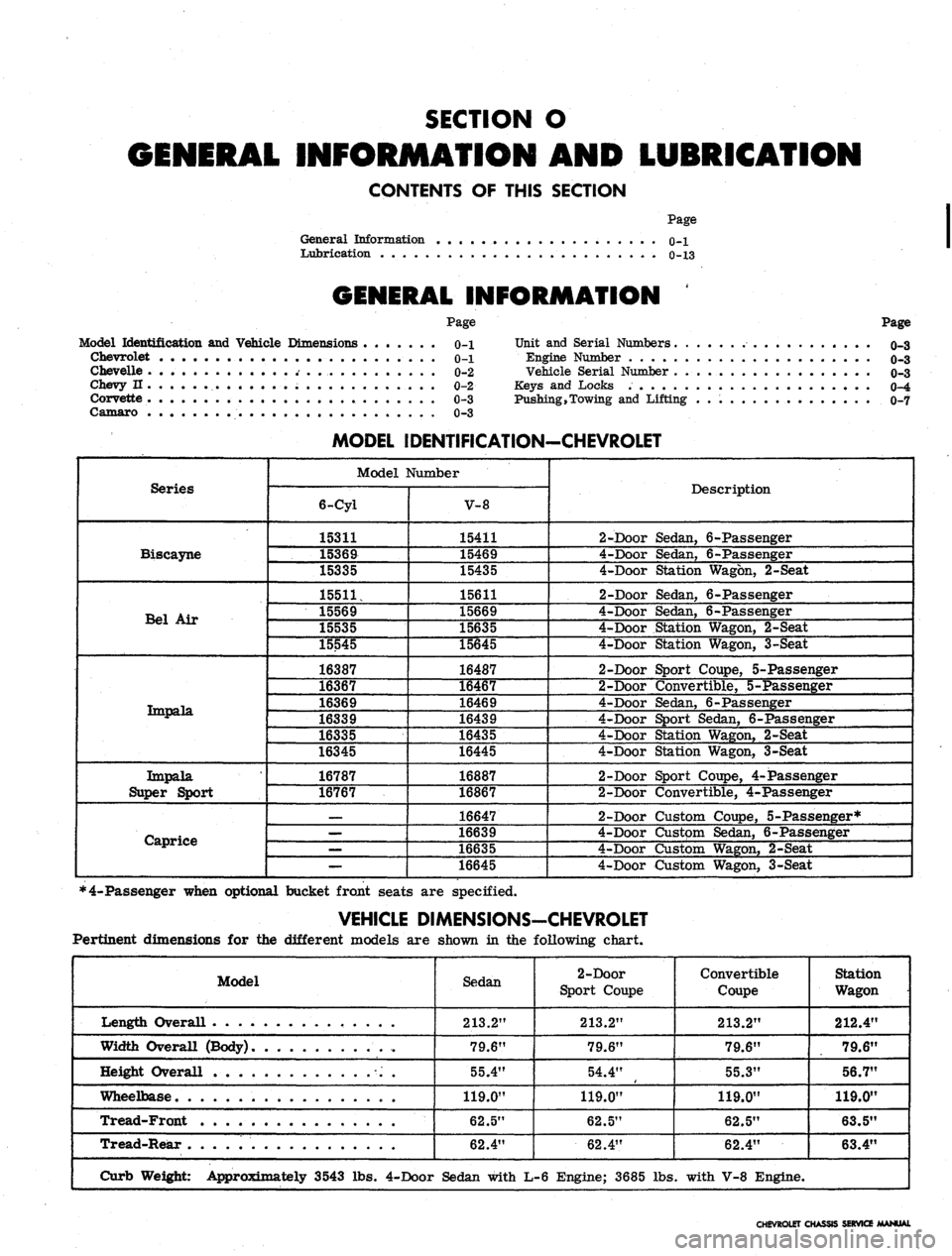
MODEL IDENTIFICATION-CHEVROLET
Model Number
6-Cyl
15311
15369
15335
15511,
15569
15535
15545
16387
16367
16369
16339
16335
16345
16787
16767
—
—
—
—
V-8
15411
15469
15435
15611
15669
15635
15645
16487
16467
16469
16439
16435
16445
16887
16867
16647
16639
16635
16645
Description
2-Door Sedan, 6-Passenger
4-Door Sedan, 6-Passenger
4-Door Station Wagon, 2-Seat
2-Door Sedan, 6-Passenger
4-Door Sedan, 6-Passenger
4-Door Station Wagon, 2-Seat
4-Door Station Wagon, 3-Seat
2-Door Sport Coupe, 5-Passenger
2-Door Convertible, 5-Passenger
4-Door Sedan, 6-Passenger
4-Door Sport Sedan, 6-Passenger
4-Door Station Wagon, 2-Seat
4-Door Station Wagon, 3-Seat
2-Door Sport Coupe, 4-Passenger
2-Door Convertible, 4-Passenger
2-Door Custom Coupe, 5-Passenger*
4-Door Custpm Sedan, 6-Passenger
4-Door Custom Wagon, 2-Seat
4-Door Custom Wagon, 3-Seat
*4-Passenger when optional bucket front seats are specified.
VEHICLE DIMENSIONS-CHEVROLET
Pertinent dimensions for the different models are shown in the following chart.
Model
Length Overall . .
Width Overall (Body)
Height Overall
Wheelbase
Tread-Front
Tread-Rear
Curb Weight: Approximately 3543 lbs.
Sedan
213.2"
79.6"
55.4"
119.0"
62.5"
62.4"
4-Door Sedan with
2-Door
Sport Coupe
213.2"
79.6"
54.4"
119.0"
62.5"
62.4"
L-6 Engine; 3685 lbs
Convertible
Coupe
213.2"
79.6"
55.3"
119.0"
62.5"
62.4"
. with V-8 Engine.
Station
Wagon
212.4"
79.6"
56.7"
119.0"
63.5"
63.4"
CHEVROLET CHASSIS SERVICE MANUAL
Page 6 of 659
GENERAL INFORMATION 0-4
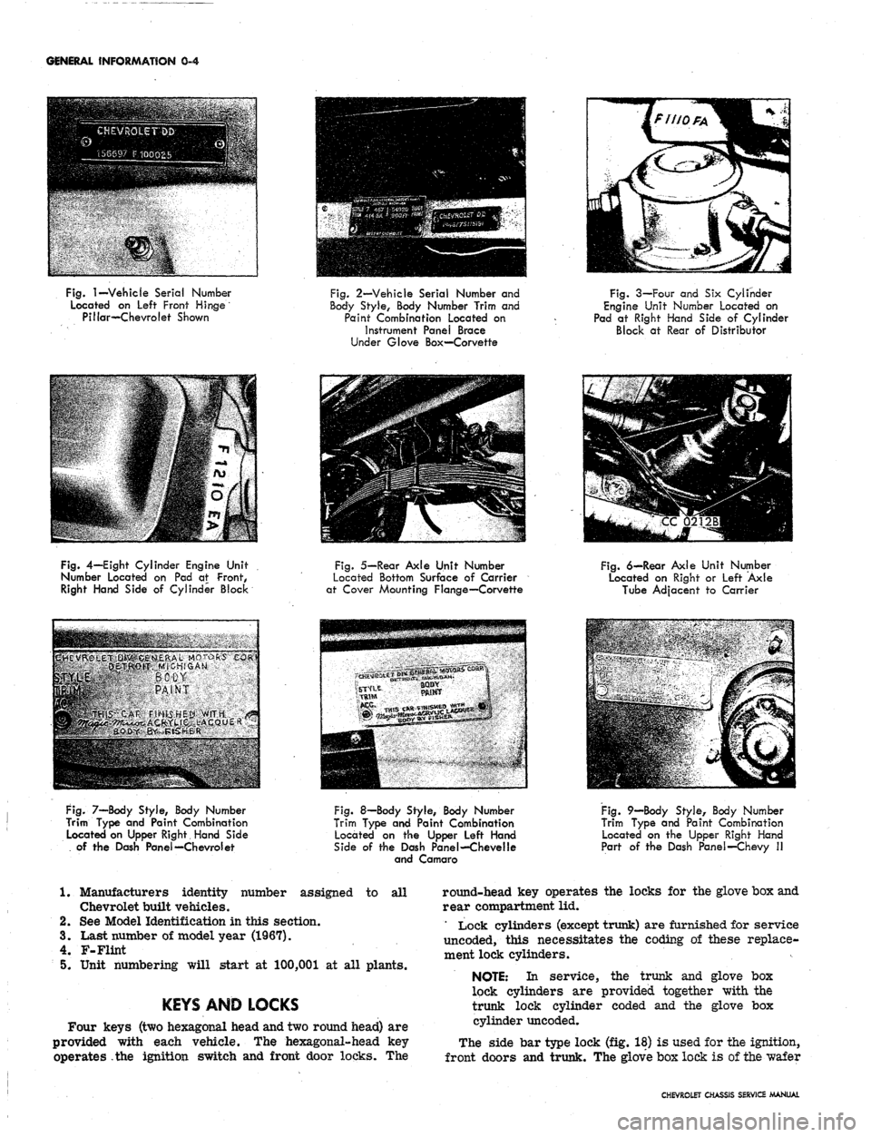
Fig.
1—Vehicle
Serial Number
Located on Left Front Hinge
Pillar—Chevrolet Shown
Fig.
2—Vehicle Serial Number and
Body Style, Body Number Trim and
Paint Combination Located on
Instrument Panel Brace
Under Glove Box—Corvette
Fig. 3—Four and Six Cylinder
Engine Unit Number Located on
Pad at Right Hand Side of Cylinder
Block at Rear of Distributor
Fig.
4—Eight Cylinder Engine Unit
Number Located on Pad at Front,
Right Hand Side of Cylinder Block
Fig.
5—Rear Axle Unit Number
Located Bottom Surface of Carrier
at Cover Mounting Flange—Corvette
Fig.
6—Rear Axle Unit Number
Located on Right or Left Axle
Tube Adjacent to Carrier
BSHfi^;^
PAINT
HRIKI5"tM>
fIHIsS
HE|St.>MfT*
^^ * *•'"
•<"'
Fig.
7—Body Style, Body Number
Trim Type and Paint Combination
Located on Upper Right Hand Side
of the Dash Panel—Chevrol et
Fig.
8—Body Style, Body Number
Trim Type and Paint Combination
Located on the Upper Left Hand
Side of the Dash Panel—Chevelle
and Camaro
Fig.
9—Body Style, Body Number
Trim Type and Paint Combination
Located on the Upper Right Hand
Part of the Dash Panel—Chevy II
1. Manufacturers identity number assigned to all
Chevrolet built vehicles.
2.
See Model Identification in this section.
3.
Last number of model year (1967).
4.
F-Flint
5.
Unit numbering will start at 100,001 at all plants.
KEYS AND LOCKS
Four keys (two hexagonal head and two round head) are
provided with each vehicle. The hexagonal-head key
operates the ignition switch and front door locks. The
round-head key operates the locks for the glove box and
rear compartment lid.
' Lock cylinders (except trunk) are furnished for service
uncoded, this necessitates the coding of these replace-
ment lock cylinders.
NOTE: In service, the trunk and glove box
lock cylinders are provided together with the
trunk lock cylinder coded and the glove box
cylinder uncoded.
The side bar type lock (fig. 18) is used for the ignition,
front doors and trunk. The glove box lock is of the wafer
CHEVROLET CHASSIS SERVICE MANUAL
Page 7 of 659
GENERAL INFORMATION 0-5
Fig.
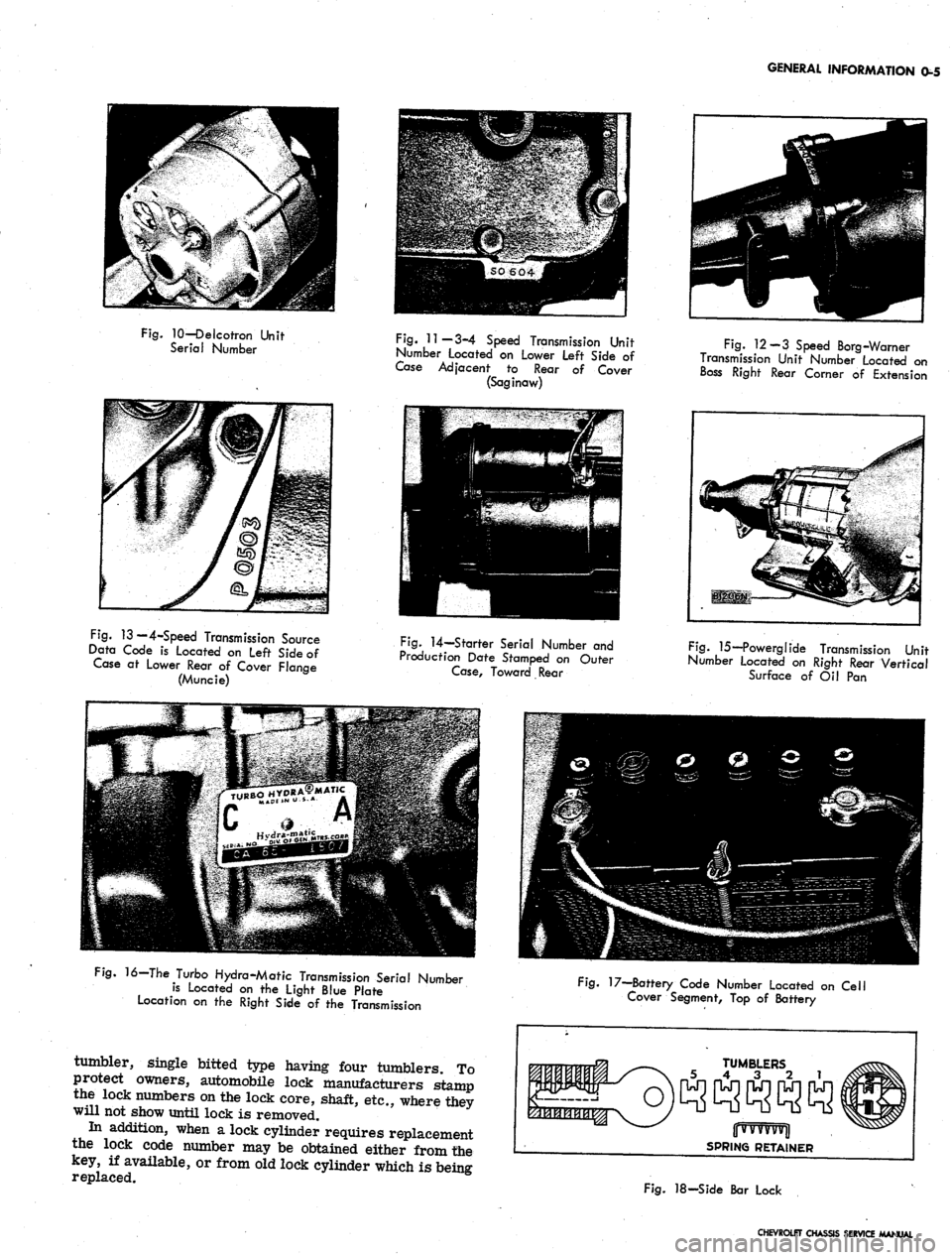
10—Delcotron Unit
Serial Number
Fig.
11—3-4 Speed Transmission Unit
Number Located on Lower Left Side of
Case Adjacent to Rear of Cover
(Saginaw)
Fig.
12-3 Speed Borg-Warner
Transmission Unit Number Located on
Boss Right Rear Comer of Extension
Fig.
13 — 4-Speed Transmission Source
Data Code is Located on Left Side of
Case at Lower Rear of Cover Flange
(Muncie)
Fig.
14—Starter Serial Number and
Production Date Stamped on Outer
Case,
Toward Rear
Fig.
15—Powerglide Transmission Unit
Number located on Right Rear Vertical
Surface of Oil Pan
16—The Turbo Hydra-Matic Transmission Serial Number
is Located on the Light Blue Plate
Location on the Right Side of the Transmission
tumbler, single bitted type having four tumblers. To
protect owners, automobile lock manufacturers stamp
the lock numbers on the lock core, shaft, etc., where they
will not show until lock is removed.
In addition, when a lock cylinder requires replacement
the lock code number may be obtained either from the
key, if available, or from old lock cylinder which is being
replaced.
Fig.
17—Battery Code Number Located on Cell
Cover Segment, Top of Battery
TUMBLERS
5 4 3 2 1
jjwvvvvvjl
SPRING RETAINER
Fig.
18-Side Bar Lock
CHEVROLET CHASSIS SERVICE MANUAL
Page 8 of 659
GENERAL INFORMATION
0-6
Once the code number of the lock is obtained look up
this number in a key cutting book.
All side bar locks (except trunk) furnished to the field
by the Parts' Department are uncoded, that is, they are
furnished without tumblers, springs or spring retainers,
these parts are serviced separately. The tumblers come
in five different depths, indicated by numbers.
The side bar locks have six tumbler positions, and in
looking up the cutting code, the following may be used as
an example. After key code number is determined, either
from key or from number stamped on lock cylinder refer
to your code book and record the key cutting information
as follows:
Key of Lock
Code Number
0V11
Cutting or Tumbler
position from head
of lock
Key Cutting
Code Numerical
545431
123456
NOTE:
Key blanks used for ignition and door
locks are stamped with an "A" while rear com-
partment and glove box blanks are stamped with
a "B".
The number that is written above the cutting or tumbler
position indicates each different tumbler which is to be
dropped into each tumbier slot of the lock.
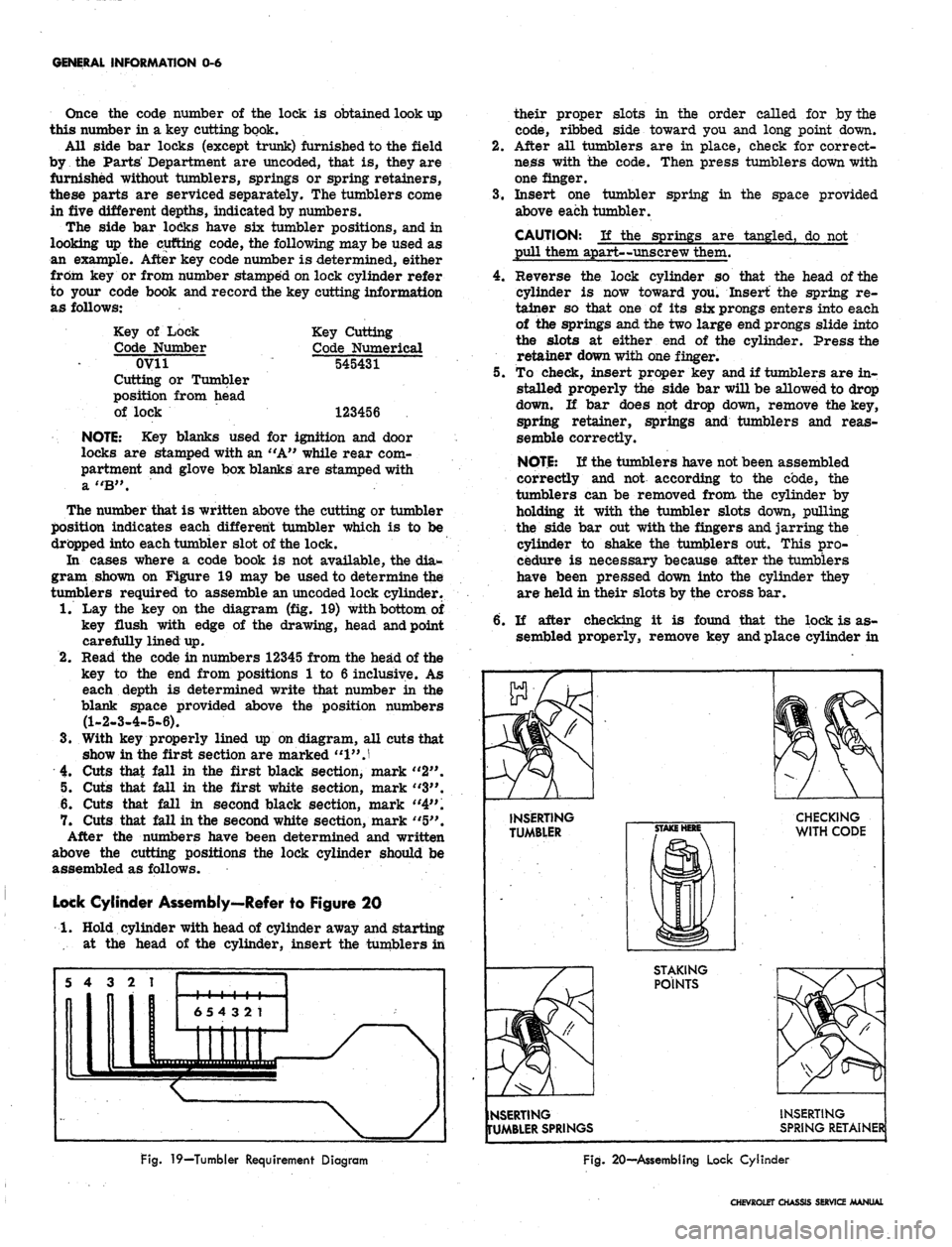
In cases where a code book is not available, the dia-
gram shown on Figure 19 may be used to determine the
tumblers required to assemble an uncoded lock cylinder.
1.
Lay the key on the diagram (fig. 19) with bottom of
key flush with edge of the drawing, head and point
carefully lined up.
2.
Read the code in numbers 12345 from the head of the
key to the end from positions 1 to 6 inclusive. As
each depth is determined write that number in the
blank space provided above the position numbers
(1-2-3-4-5-6).
3.
With key properly lined up on diagram, all cuts that
show in the first section are marked
"1"
J
4.
Cuts that fall in the first black section, mark "2".
5. Cuts that fall in the first white section, mark "3".
6. Cuts that fall in second black section, mark "4".
7. Cuts that fall in the second white section, mark "5".
After the numbers have been determined and written
above the cutting positions the lock cylinder should be
assembled as follows.
Lock Cylinder Assembly—Refer to Figure 20
1.
Hold cylinder with head of cylinder away and starting
•... at the head of the cylinder, insert the tumblers in
their proper slots in the order called for by the
code, ribbed side toward you and long point down.
2.
After all tumblers are in place, check for correct-
ness with the code. Then press tumblers down with
one finger.
3.
Insert one tumbler spring in the space provided
above each tumbler.
CAUTION: If the springs are tangled, do not
pull them apart—unscrew them.
4.
Reverse the lock cylinder so that the head of the
cylinder is now toward you. Insert the spring re-
tainer so that one of its six prongs enters into each
of the springs and the two large end prongs slide into
the slots at either end of the cylinder. Press the
retainer down with one finger.
5. To check, insert proper key and if tumblers are in-
stalled properly the side bar will be allowed to drop
down. If bar does not drop down, remove the key,
spring retainer, springs and tumblers and reas-
semble correctly.
NOTE:
If the tumblers have not been assembled
correctly and not according to the code, the
tumblers can be removed from the cylinder by
holding it with the tumbler slots down, pulling
the side bar out with the fingers and jarring the
cylinder to shake the tumblers out. This pro-
cedure is necessary because after the tumblers
have been pressed down into the cylinder they
are held in their slots by the cross bar.
6. If after checking it is found that the lock is as-
sembled properly, remove key and place cylinder in
INSERTING
TUMBLER
CHECKING
WITH CODE
STAKING
POINTS
NSERTING
TUMBLER SPRINGS
INSERTING
SPRING RETAINER
Fig.
19—Tumbler Requirement Diagram
Fig.
20—Assembling Lock Cylinder
CHEVROLET CHASSIS SERVICE MANUAL
Page 9 of 659
GENERAL INFORMATION 0-7
a vise using leather or wood on each side to prevent
damage to the cylinder,
7. Stake the retainer securely in place by staking the
cylinder metal over both edges of the retainer ends
using a suitable staking tool at right angles to the
top of the retainer and from the cast metal of the
cylinder over the retainer at each corner.
PUSHING, TOWING AND LIFTING
Pushing
NOTE:
Towing car to start is not recommended
due to the possibility of the disabled car ac-
celerating into tow car.
AUTOMATIC TRANSMISSION
Do not attempt to start the engine by pushing the car.
Should the battery become discharged, it will be neces-
sary to use an auxiliary battery with jumper cables to
start the engine.
CAUTION: To prevent damage to electrical
system, never connect booster batteries in ex-
cess of 12 volts and connect positive to positive
and negative to negative.
Manual Transmission
When a push start is necessary turn off all electrical
loads such as heater, radio, and if possible, lights, turn
on the key, depress the clutch, and place the shift lever
in high gear. Release the clutch when your speed reaches
10 to 15 miles per hour.
TOWING
The car may be towed safely on its rear wheels with
the (selector lever in "N" (Neutral) position at speeds
of 35 miles per hour or less under most conditions.
However, the drive shaft must be disconnected or the
car towed on its front wheels if 1) Tow speeds in excess
of 35 MPH are necessary, 2) Car must be towed for ex-
tended distances (over 50 miles) or, 3) Transmission is
not operating properly. If car is towed on its front
wheels, the steering wheel should be secured to maintain
a straight ahead position.
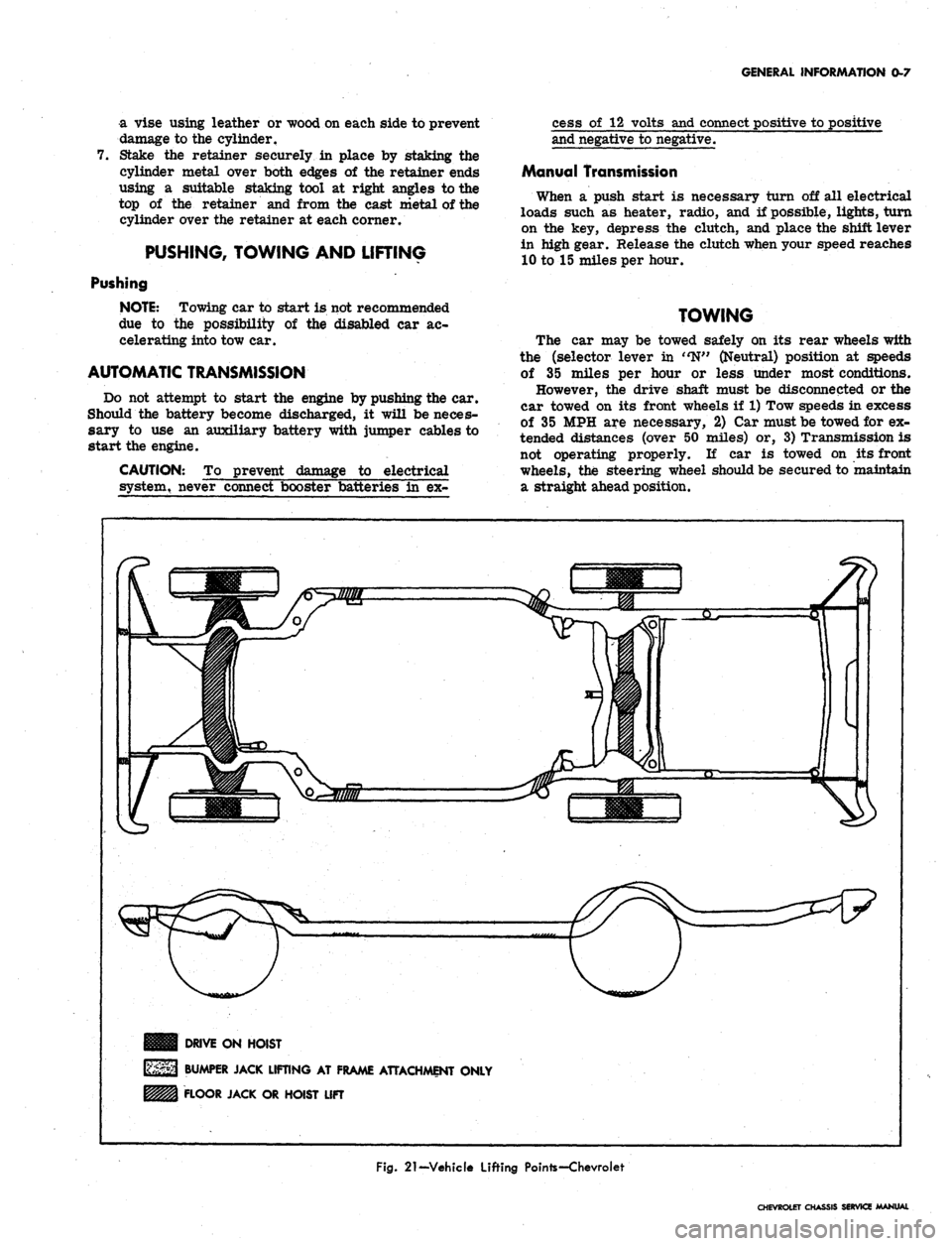
DRIVE ON HOIST
BUMPER JACK LIFTING AT FRAME ATTACHMENT ONLY
FLOOR JACK OR HOIST LIFT
Fig.
21-Vehicle Lifting Pointe-Chevroiet
CHEVROLET CHASSIS SERVICE MANUAL
Page 179 of 659
FRONT SUSPENSION 3-15
4.
Insert Spring Compressor J-
6874-
4-
5 with Adapters
J-6874-8-9 into upp^r spring tower so that lower
MU"
bolt fits into shock absorber mounting holes in
spring seat (fig. 23). Secure the two lower studs to
the spring seat with nuts.
5.
Fit the tool upper pilot to top of spring and compress
spring by tightening upper nut (fig. 24). Compress
spring until screw is bottomed out.
6. Remove lower spring seat retaining nuts, lift spring
and seat assembly from control arm and guide it
down and out through fender skirt (fig. 25).
Spring Seat Replacement (Fig. 26)
1.
Release spring tension and disconnect spring com-
pressor from spring seat.
2.
Install new spring seat to spring compressor.
Installation
1.
If spring is to be replaced, install new spring into
tool and compress spring until screw is bottomed
out.
NOTE: Spring coil ends must be against spring
stops in upper and lower seats.
2.
Lift spring and tool assembly into place and position
so that the upper spring stop is inboard.
NOTE: Locating tab on upper spring seat may
be flattened before reinstalling spring.
3.
Install lower spring seat to control arm and torque
nuts as shown in the Specifications.
4.
Loosen spring compressor until spring is properly
seated in upper spring tower and remove.
5.
Install shock abosrber as outlined under Shock Ab-
sorber—Installation in this section.
Corvette
Removal
1.
With car on suitable hoist or jack, (support vehicle
by frame so control arms may swing free) remove
wheel and tire assembly, stabilizer bar and shock
absorber. Loosen the lower ball joint to steering
knuckle nut, and the' two lower control arm cross
shaft bushing bolts.
2.
Place Tool J-6874-1 across top of sixth coil (ap-
prox.),
then loosely secure Tool J-6874-2 to the up-
per shoe, with attaching capscrews and lock washers.
The upper shoe "V" notch and lower shoe raised land
should contact spring.
3.
Insert Tool J-6874 up through center of spring and
attach to upper and lower shoe assembly.
4.
Position spacers under shock absorber mounting hole
and against bottom of lower control arm. Install
special bearing washer and Tool J-6874-5. Locate
bearing against spacer and large washer against
bearing. Feed screw up through large washer bear-
ing and spacer and thread into Tool J-6874 and
tighten snugly (fig. 22).
5.
Center shoe assembly on spring and tighten screw
until a very slight compression is placed on spring
(fig. '22). Then firmly tighten down the two cap-
screws securing the upper and lower shoes to lock
these shoes to spring.
6. Turn head of screw until spring is compressed just
enough to clear the spring tower, then remove the
lower ball joint to steering knuckle nut (fig. 22).
NOTE: It may be necessary to assist the
spring out of the spring tower with a pry bar or
a similar tool.
7.
Disconnect the lower ball joint from the steering
knuckle and lower the control arm with the com-
pressed spring. Immediately release compression
on spring by backing off long screw. Release spring
and tool and withdraw spring.
CAUTION: The spring force under compres-
sion is very large. Exercise every safety pre-
caution when performing this operation to see
that individuals and materials subject to damage
are removed from the path of the spring when
the control arm is being lowered. Also, the
compressed spring
be relaxed immedi-
ately after lowering the control arm to reduce
the time of exposure to the large compressive
force.
Installation
1.
Position spring with closely coiled end up. Place
Tool J-6874-1 across the top of the sixth coil (ap-
prox.) then loosely secure Tool J-6874-2 to the
upper shoe with attaching capscrews and lock wash-
ers.
The upper shoe MV" notch and lower shoe
raised land should contact spring.
2.
Insert Tool J-6874 up through center of spring and
attach to upper and lower shoe assembly with bolt
and nut.
3.
Set spring in its seat on the lower control arm.
4.
Position spacers centrally under shock absorber
mounting hole and against bottom of lower control
arm. Install bearing, large washer and Tool
J-6874-5.
Locate bearing against spacer and large
washer against bearing. Feed the screw up through
large washer, bearing and spacer and thread into
yoke rod. Tighten snugly, but do not start to draw
down yet
5.
Center the shoe assembly on the spring and tighten
the lag screw until a very slight compression is
placed on spring, then firmly tighten down the two
capscrews securing the upper and lower shoes. This
will lock the shoes to the coil spring.
6. Turn head of screw until spring is compressed just
enough to clear the spring tower.
NOTE: It may be necessary to assist the
spring into the spring tower with a pry bar or
similar tool.
7.
Immediately install the lower ball joint into steering
knuckle and secure in place with attaching nut.
8. Release compression on spring and at the same time
use a drift to guide the coil spring into its proper
seat. End of coils must be 3/8" from coil stops in
spring seat.
9. Tighten the lower ball joint to steering knuckle nut
and lock with cotter key.
10.
Install shock absorber and stabilizer bar.
11.
Install wheel, tire and drum assembly.
12.
Remove car from hoist or jack stands.
13.
Tighten the two lower control cross shaft bushing
bolts to 45-55 lbs. ft. torque.
NOTE: If a suitable adjustable jack-stand is
CHEVROLET CHASSIS SERVICE MANUAL
Page 284 of 659
ENGINE 6-19
OIL SEAL (REAR MAIN)
Replacement
The rear main bearing oil seal can be replaced (both
halves) without removal of the crankshaft.
NOTE:
Always replace the upper and lower
seal as a unit. Install with the lip facing toward
the front of the engine.
1.
With the oil pan removed, remove the rear main
bearing cap.
2.
Remove oil seal from the groove by lifting the end
tab (fig. 7L) then clean seal groove.
3.
Lubricate the lip and O.D. of a new seal with engine
oil. Keep oil off the parting line surface. Insert
seal in cap and roll it into place with finger and
thumb,
using light pressure so beads on seal O.D.
are not cut by seal groove at cap parting line. Be
sure tabs on seal are properly located in cross
grooves.
4.
To remove the upper half of the seal, use a small
hammer to tap a brass pin punch on one end of seal
until it protrudes far enough to be removed with
pliers (fig. 8L).
NOTE:
Always clean crankshaft surface re-
moving all foreign deposits before installing a
new seal. Also clean seal groove.
5. Lubricate the lip and O.D. of a new seal with engine
oil. Keep oil off the parting line surface. Gradually
push with a hammer handle, while turning crank-
shaft, until seal is rolled into place. (Similar to in-
stalling a main bearing.) Be careful that seal bead
on O.D. is not cut. Compress seal towards crank-
shaft as much as possible.
6. Install the rear main bearing cap (with new seal) and
torque to specifications. Be sure cross seal tabs
are in place and properly seated.
CRANKSHAFT PULLEY AND HUB
(Chevy II with L4 Engine)
Removal
1.
Drain radiator and disconnect upper and lower radi-
ator hoses at radiator.
2.
Remove radiator core as outlined in Section 13.
3.
Remove fan belt. Remove crankshaft pulley from
pulley hub.
4.
Install puller Tool J-6978 to pulley hub with two
3/8"
x 2" and one 5/16" x 2" bolts and remove hub
then remove puller tool.
Installation
1.
Coat oil seal contact area on hub with engine oil
position hub over crankshaft and key and start hub
into position with a mallet. Using Tool J-5590 drive
onto crankshaft until it bottoms against crankshaft
gear.
NOTE:
Crankshaft extends slightly through hub
and a tool is necessary to drive hub completely
into bottomed position.
2.
Install pulley onto hub.
NOTE:
There are two 3/8" holes and one
5/16" hole that must be matched on hub in order
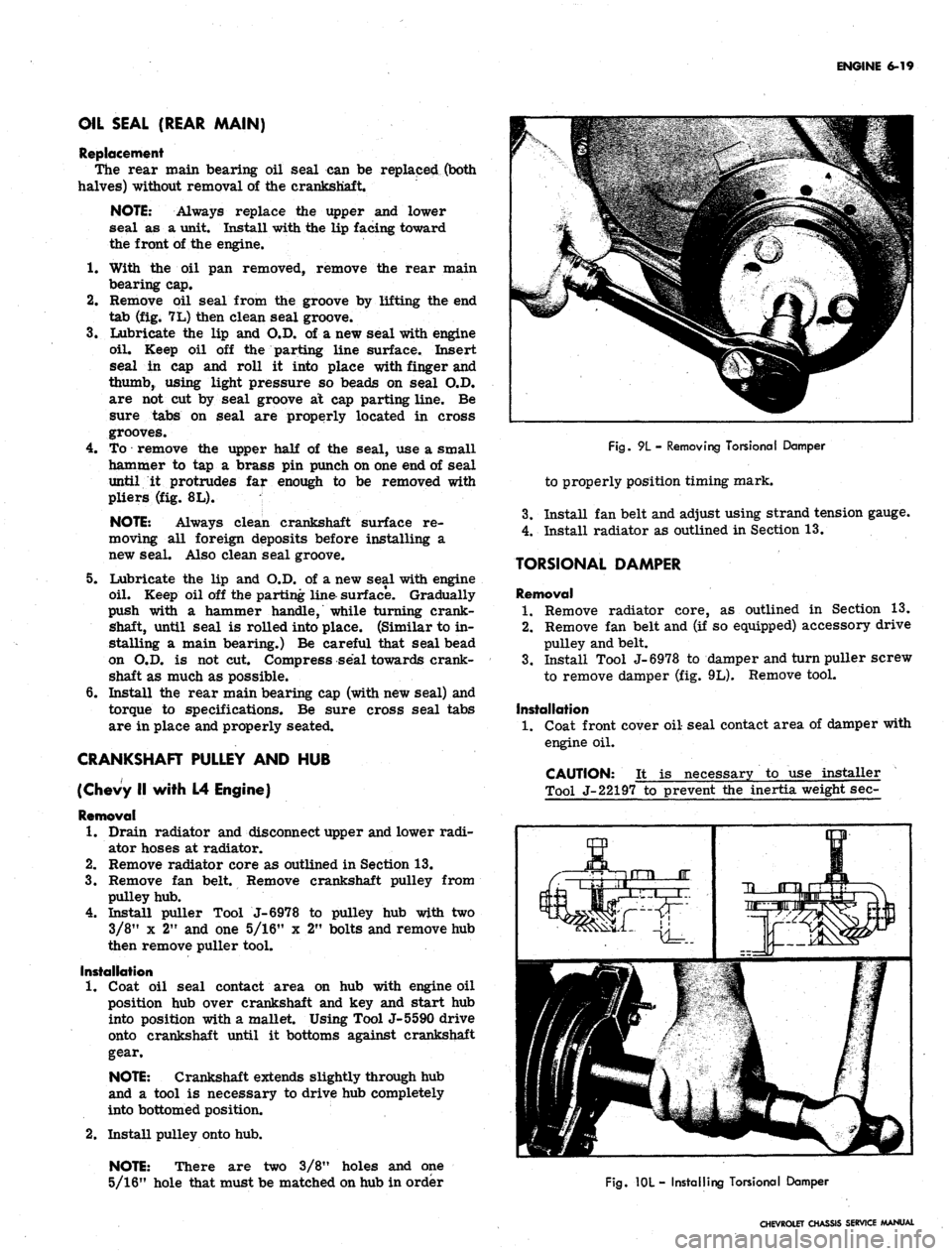
Fig.
9L - Removing Torsional Damper
to properly position timing mark.
3.
Install fan belt and adjust using strand tension gauge.
4.
Install radiator as outlined in Section 13.
TORSIONAL DAMPER
Removal
1.
Remove radiator core, as outlined in Section 13.
2.
Remove fan belt and (if so equipped) accessory drive
pulley and belt.
3.
Install Tool J-6978 to damper and turn puller screw
to remove damper (fig. 9L). Remove tool.
Installation
1.
Coat front cover oil seal contact area of damper with
engine oil.
CAUTION: It is necessary to use installer
Tool J-22197 to prevent the inertia weight sec-
Fig.
10L - Installing Torsional Damper
CHEVROLET CHASSIS SERVICE MANUAL
Page 298 of 659
ENGINE 6-33
Fig.
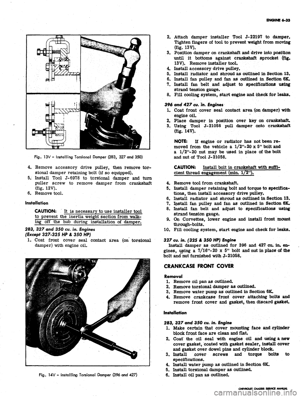
13V - Installing TorsionaI Damper (283, 327 and 350)
4.
Remove accessory drive pulley, then remove tor-
sional damper retaining bolt (if so equipped).
5. Install Tool J-6978 to torsional damper and turn
puller screw to remove damper from crankshaft
(fig. 12V).
6. Remove tool.
Installation
CAUTION: It is necessary to use installer tool
to prevent the inertia weight section from walk-
ing off the hub during installation of damper.
283, 327 and 350 cu. in. Engines
(Except 327-325 HP & 350 HP)
1.
Coat front cover seal contact area (on torsional
damper) with engine oil.
Fig.
14V - Installing Torsional Damper (396 and 427)
2.
Attach damper installer Tool J-22197 to damper.
Tighten fingers of tool to prevent weight from moving
(fig. 13V).
3.
Position damper on crankshaft and drive into position
until it bottoms against crankshaft sprocket (fig.
13V).
Remove installer tool.
4.
Install accessory drive pulley.
5. Install radiator and shroud as outlined in Section 13.
6. Install fan pulley and fan as outlined in Section 6K.
7. Install fan belt and adjust to specifications using
strand tension gauge.
8. Fill cooling system, start engine and check for leaks.
396 and 427
cu.
in.
Engines
1.
Coat front cover seal contact area (on damper) with
engine oil.
2.
Place damper in position over key on crankshaft.
3.
Using Tool J-21058 pull damper onto crankshaft
(fig. 14V).
NOTE:
If engine or radiator has not been re-
moved from the vehicle a 1/2"- 20 x 5" bolt and
a
1/2"-20
nut may be used in place of the bolt
and nut of Tool J-21058.
CAUTION: Install bolt in crankshaft with suffi-
cient thread engagement (min. 1/2").
4.
Remove tool from crankshaft.
5. Install damper retaining bolt and torque to specifica-
tions,
then install accessory drive pulley.
6. Install radiator and shroud as outlined in Section 13.
7. Install fan pulley and fan as outlined in Section 6K.
8. Install fan belt and adjust to specifications using
strand tension gauge.
9. On Corvettes, lower engine and install front mount
through-bolts.
10.
Fill cooling system, start engine and check for leaks.
327
cu.
in. (325 & 350 HP)
Engine
Install damper as outlined for 396 and 427 cu. in. en-
gines,
using a 7/16"-20 x 5" bolt and nut in place of the
bolt and nut furnished with J-21058.
CRANKCASE FRONT COVER
Removal
1.
Remove oil pan as outlined.
2.
Remove torsional damper as outlined.
3.
Remove water pump as outlined in Section 6K.
4.
Remove crankcase front cover attaching bolts and
remove front cover and gasket, then discard gasket
Installation
283, 327 and 350 cu. in.
Engine
1.
Make certain that cover mounting face and cylinder
block front face are clean and flat.
2.
Coat the oil seal with engine oil and using a new
cover gasket, coated with gasket sealer, install cover
and gasket over dowel pins and cylinder block.
3.
Install cover screws and torque bolts to
specifications.
4.
Install water pump as outlined in Section 6K.
5. Install torsional damper as outlined.
6. Install oil pan as outlined.
CHEVROLET CHASSIS SOVKZ MANUAL
Page 332 of 659
ENGINE-ELECTRICAL 6Y-7
CHARGING SYSTEM
INDEX
Page
General Description . 6Y-7
Maintenance and Adjustments 6Y-9
Static Checks . 6Y-10
System Condition Check and Voltage
•Regular Adjustment. 6Y-10
General Output 6Y-11
Generator Diode and Field Test 6Y-12
Indicator Lamp-Initial Field Excitation
Circuit Tests . 6Y-12
Page
Field Circuit Resistance Wire Tests 6Y-13
Field Relay Test and Adjustment 6Y-14
Other Harness Checks 6Y-14
Service Operations 6Y-14
Generator 6Y-14
Removal and Installation 6Y-14
Pulley Replacement. 6Y-14
Brush Replacement (6" Delcotron). 6Y-15
Double Contact Regulator . . . . . . 6Y-16
GENERAL DESCRIPTION
The charging system includes the battery, generator,
regulator, telltale light, and necessary wiring to connect
these components. The Delcotron is offered as standard
equipment, although there are various capacities avail-
able on all models.
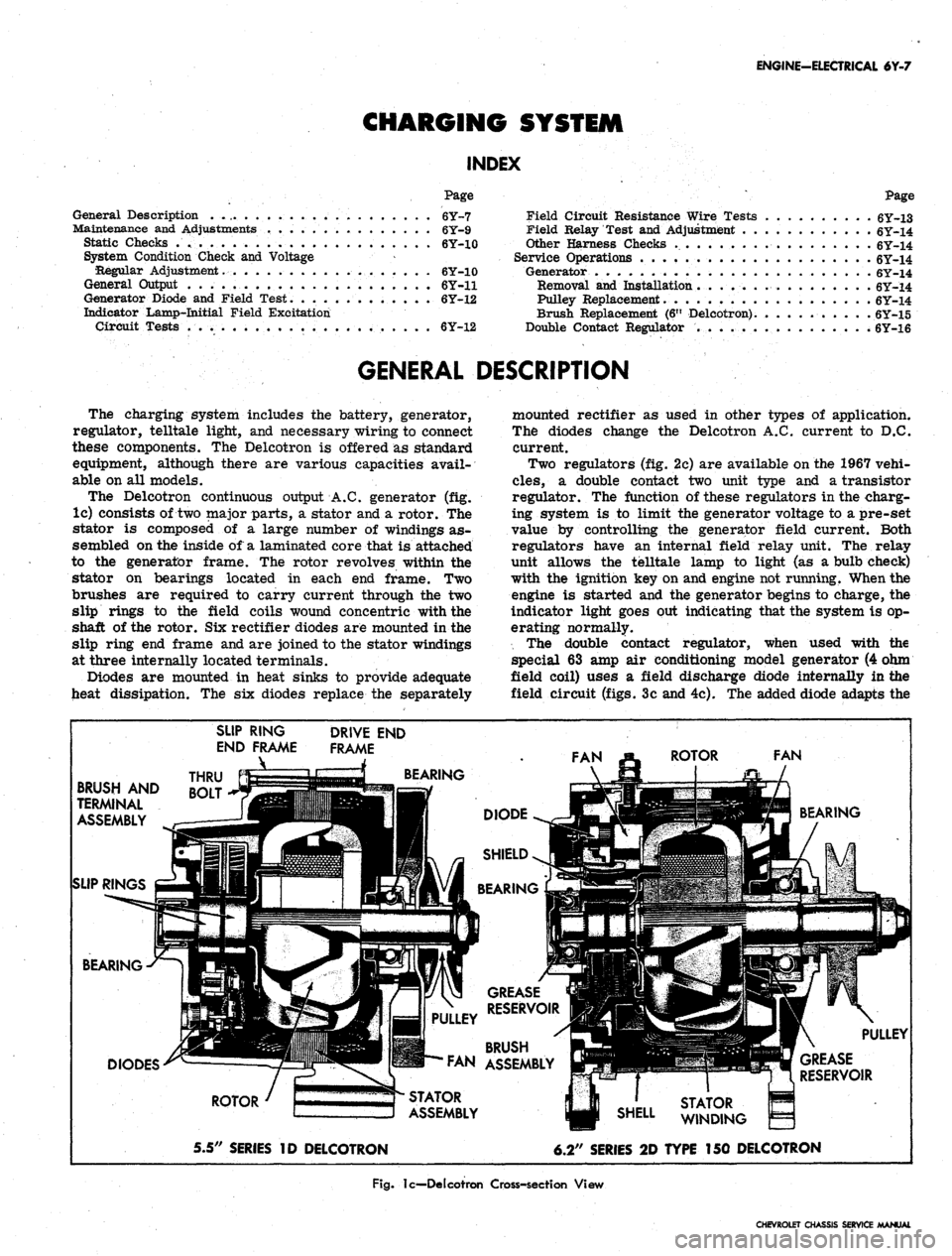
The Delcotron continuous output A.C. generator (fig.
lc) consists of two major parts, a stator and a rotor. The
stator is composed of a large number of windings as-
sembled on the inside of a laminated core that is attached
to the generator frame. The rotor revolves within the
stator on bearings located in each end frame. Two
brushes are required to carry current through the two
slip rings to the field coils wound concentric with the
shaft of the rotor. Six rectifier diodes are mounted in the
slip ring end frame and are joined to the stator windings
at three internally located terminals.
Diodes are mounted in heat sinks to provide adequate
heat dissipation. The six diodes replace the separately
mounted rectifier as used in other types of application.
The diodes change the Delcotron A.C. current to D.C.
current.
Two regulators (fig. 2c) are available on the 1967 vehi-
cles,
a double contact two unit type and a transistor
regulator. The function of these regulators in the charg-
ing system is to limit the generator voltage to a pre-set
value by controlling the generator field current. Both
regulators have an internal field relay unit. The relay
unit allows the telltale lamp to light (as a bulb check)
with the ignition key on and engine not running. When the
engine is started and the generator begins to charge, the
indicator light goes out indicating that the system is op-
erating normally.
The double contact regulator, when used with the
special 63 amp air conditioning model generator (4 ohm
field coil) uses a field discharge diode internally in the
field circuit (figs. 3c and 4c). The added diode adapts the
BRUSH AND
TERMINAL
ASSEMBLY
SLIP RINGS
SLIP RING
END FRAME
_\
THRU
BOLT
DRIVE END
FRAME
BEARING
BEARING
DIODES
ROTOR
5.5" SERIES ID DELCOTRON
STATOR
ASSEMBLY
GREASE
RESERVOIR
BRUSH
FAN ASSEMBLY
6.2" SERIES 2D TYPE 150 DELCOTRON
Fig.
lc—Delcotron Cross-section View
CHEVROLET CHASSIS SERVICE MANUAL
Page 354 of 659
ENGINE-ELECTRICAL 6Y-29
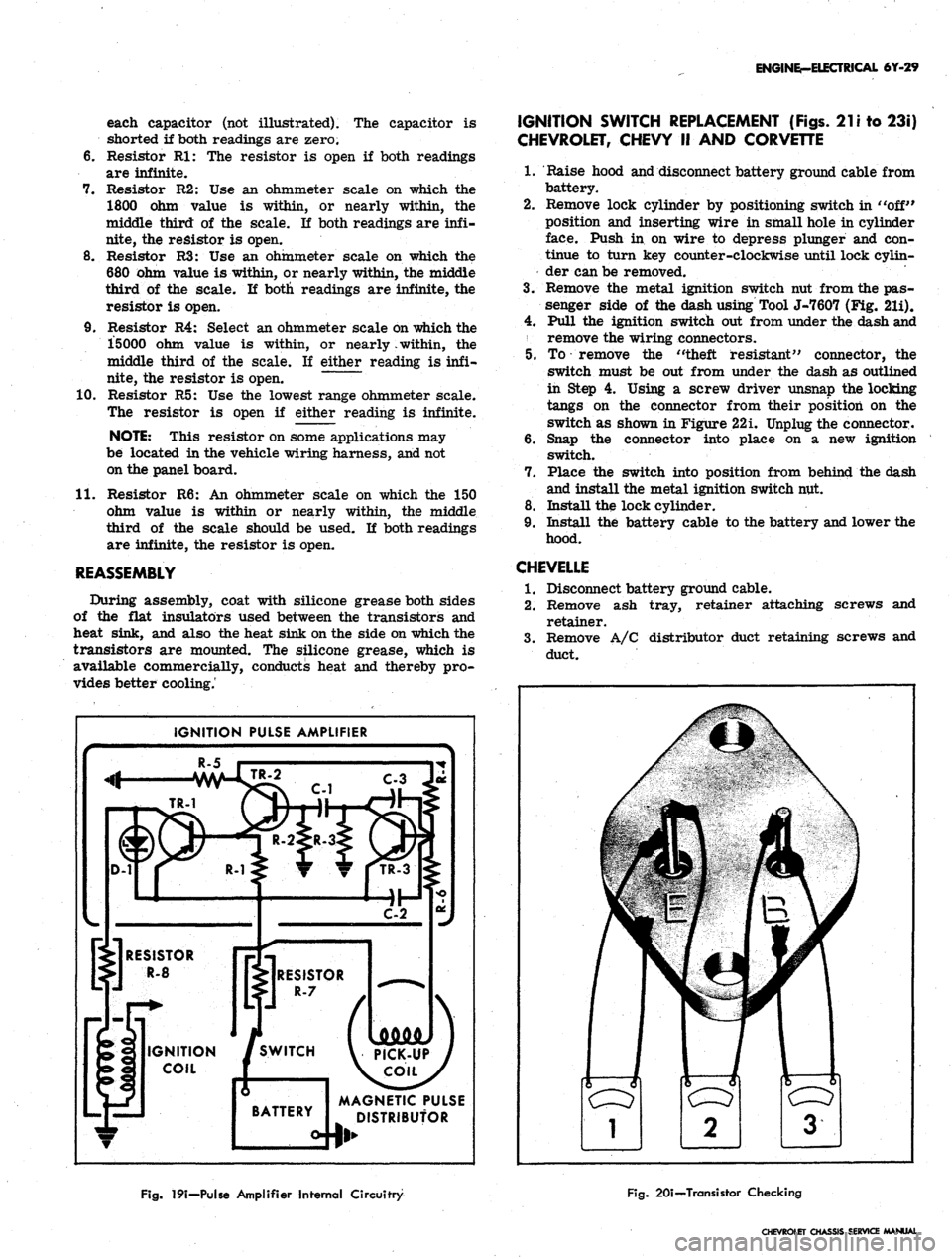
each capacitor (not illustrated). The capacitor is
shorted if both readings are zero.
6. Resistor Rl: The resistor is open if both readings
are infinite.
7. Resistor R2: Use an ohmmeter scale on which the
1800 ohm value is within, or nearly within, the
middle third of the scale. If both readings are infi-
nite, the resistor is open.
8. Resistor R3: Use an ohmmeter scale on which the
680 Ohm value is within, or nearly within, the middle
third of the scale. If both readings are infinite, the
resistor is open.
9. Resistor R4: Select an ohmmeter scale on which the
15000 ohm value is within, or nearly .within, the
middle third of the scale. If either reading is infi-
nite, the resistor is open. ~
10.
Resistor R5: Use the lowest range ohmmeter scale.
The resistor is open if either reading is infinite.
NOTE:
This resistor on some applications may
be located in the vehicle wiring harness, and not
on the panel board.
11.
Resistor R6: An ohmmeter scale on which the 150
ohm value is within or nearly within, the middle
third of the scale should be used. If both readings
are infinite, the resistor is open.
REASSEMBLY
During assembly, coat with silicone grease both sides
of the flat insulators used between the transistors and
heat sink, and also the heat sink on the side on which the
transistors are mounted. The silicone grease, which is
available commercially, conducts heat and thereby pro-
vides better cooling.'
IGNITION PULSE AMPLIFIER
R-5
C-3 Ju
MAGNETIC PULSE
DISTRIBUTOR
IGNITION SWITCH REPLACEMENT (Figs.
21
i to 23i)
CHEVROLET, CHEVY II AND CORVETTE
1.
Raise hood and disconnect battery ground cable from
battery.
2.
Remove lock cylinder by positioning switch in "off"
position and inserting wire in small hole in cylinder
face. Push in on wire to depress plunger and con-
tinue to turn key counter-clockwise until lock cylin-
der can be removed.
3.
Remove the metal ignition switch nut from the pas-
senger side of the dash using Tool J-7607 (Fig. 21i).
4.
Pull the ignition switch out from under the dash and
remove the wiring connectors.
5. To remove the "theft resistant" connector, the
switch must be out from under the dash as outlined
in Step 4. Using a screw driver unsnap the locking
tangs on the connector from their position on the
switch as shown in Figure 22i. Unplug the connector.
6. Snap the connector into place on a new ignition
switch.
7. Place the switch into position from behind the dash
and install the metal ignition switch nut.
8. Install the lock cylinder.
9. Install the battery cable to the battery and lower the
hood.
CHEVELLE
1.
Disconnect battery ground cable.
2.
Remove ash tray, retainer attaching screws and
retainer.
3.
Remove A/C distributor duct retaining screws and
duct.
Fig.
19i—Pulse Amplifier Internal Circuitry
Fig.
20i—Transistor Checking
CHEVROLET Oi