overheating CHEVROLET CAMARO 1967 1.G Chassis Workshop Manual
[x] Cancel search | Manufacturer: CHEVROLET, Model Year: 1967, Model line: CAMARO, Model: CHEVROLET CAMARO 1967 1.GPages: 659, PDF Size: 114.24 MB
Page 220 of 659

REAR SUSPENSION AND DRIVE LINE 4-30
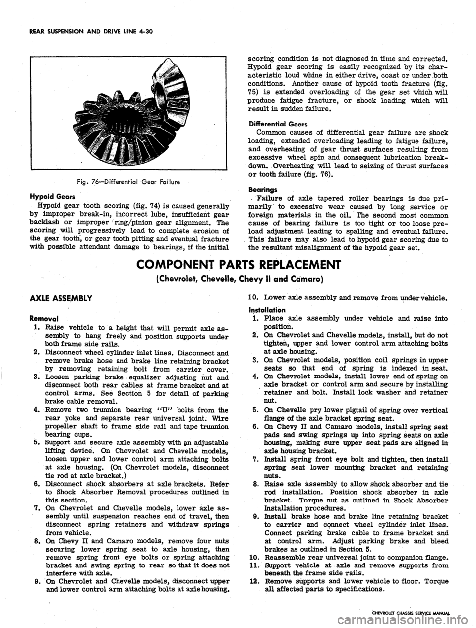
Fig.
76—Differential Gear Failure
Hypoid Gears
Hypoid gear tooth scoring (fig. 74) is caused generally
by improper break-in, incorrect lube, insufficient gear
backlash or improper 'ring/pinion gear alignment. The
scoring will progressively lead to complete erosion of
the gear tooth, or gear tooth pitting and eventual fracture
with possible attendant damage to bearings, if the initial
scoring condition is not diagnosed in time and corrected.
Hypoid gear scoring is easily recognized by its char-
acteristic loud whine in either drive, coast or under both
conditions. Another cause of hypoid tooth fracture (fig.
75) is extended overloading of the gear set which will
produce fatigue fracture, or shock loading which will
result in sudden failure.
Differential Gears
Common causes of differential gear failure are shock
loading, extended overloading leading to fatigue failure,
and overheating of gear thrust surfaces resulting from
excessive wheel spin and consequent lubrication break-
down. Overheating will lead to seizing of thrust surfaces
or tooth failure (fig. 76).
Bearings
• Failure of axle tapered roller bearings is due pri-
marily to excessive wear caused by long service or
foreign materials in the oil. The second most common
cause of bearing failure is too tight or too loose pre-
load adjustment leading to spalling and eventual failure.
This failure may also lead to hypoid gear scoring due to
the resultant misalignment of the hypoid gear set.
COMPONENT PARTS REPLACEMENT
(Chevrolet, Cheveile, Chevy II and Camaro)
AXLE ASSEMBLY
Removal
1.
Raise vehicle to a height that will permit axle as-
sembly to hang freely and position supports under
both frame side rails.
2.
Disconnect wheel cylinder inlet lines. Disconnect and
remove brake hose and brake line retaining bracket
by removing retaining bolt from carrier cover.
3.
Loosen parking brake equalizer adjusting nut and
disconnect both rear cables at frame bracket and at
control arms. See Section 5 for detail of parking
brake cable removal.
4.
Remove two trunnion bearing "U" bolts from the
rear yoke and separate rear universal joint. Wire
propeller shaft to frame side rail and tape trunnion
bearing cups.
5. Support arid secure axle assembly with an adjustable
lifting device. On Chevrolet and Cheveile models,
loosen upper and lower control arm attaching bolts
at axle housing. (On Chevrolet models, disconnect
tie rod at axle bracket.)
6. Disconnect shock absorbers at axle brackets. Refer
to Shock Absorber Removal procedures outlined in
this section.
7. On Chevrolet and Cheveile models, lower axle as-
sembly until suspension reaches end of travel, then
disconnect spring retainers and withdraw springs
from vehicle.
8. On Chevy II and Camaro models, remove four nuts
securing lower spring seat to axle housing, then
remove spring front eye bolts or spring attaching
bracket and swing spring to rear so that it does not
interfere with axle.
9. On Chevrolet and Cheveile models, disconnect upper
and lower control arm attaching bolts at axle housing*
10.
Lower axle assembly and remove from under vehicle.
Installation
1.
Place axle assembly under vehicle and raise into
position.
2.
On Chevrolet and Cheveile models, install, but do not
tighten, upper and lower control arm attaching bolts
at axle housing.
3.
On Chevrolet models, position coil springs in upper
seats so that end of spring is indexed in seat.
4.
On Chevrolet models, install lower end of spring on
axle bracket or control arm and secure by installing
retainer and bolt. Install lock washer and retainer
nut.
5. On Cheveile pry lower pigtail of spring over vertical
flange of the axle bracket spring seat.
6. On Chevy II and Camaro models, install spring seat
pads and swing springs up into spring seats on axle
housing, making sure upper seat pads are aligned in
axle housing bracket.
7. Install spring front eye bolt and tighten, then install
spring seat lower mounting bracket and retaining
nuts.
8. Raise axle assembly to allow shock absorber and tie
rod installation. Position shock absorber in axle
bracket. Torque nut as outlined in Shock Absorber
Installation procedures.
9. Install brake hose and brake line retaining bracket
to carrier and connect wheel cylinder inlet lines.
Connect parking brake cable to frame bracket and
at control arm. Adjust parking brake and bleed
brakes as outlined in Section 5.
10.
Reassemble rear universal joint to companion flange.
11.
Support vehicle at axle and remove supports from
beneath the frame side rails.
12.
Remove supports and lower vehicle to floor. Torque
all affected parts to specifications.
CHEVROLET CHASSIS SERVICE MANUAL
Page 358 of 659

ENGINE-ELECTRICAL 6Y-33
O
V-8 ENGINE
STARTING MOTOR
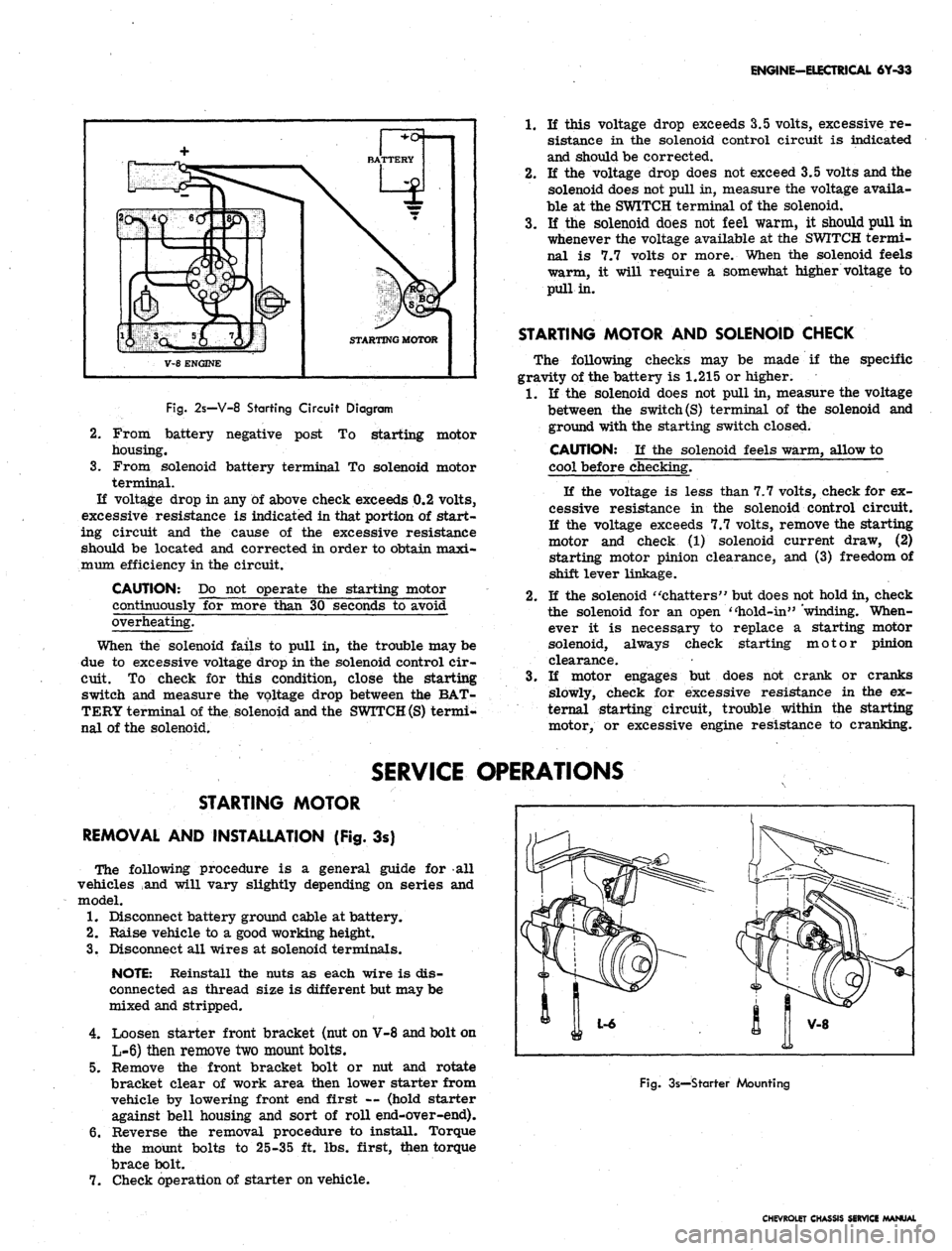
Fig.
2s—V-8 Starting Circuit Diagram
2.
3.
From battery negative post
To
starting motor
housing.
From solenoid battery terminal
To
solenoid motor
terminal.
If voltage drop
in
any
of
above check exceeds 0.2 volts,
excessive resistance
is
indicated in that portion
of
start-
ing circuit
and the
cause
of the
excessive resistance
should
be
located
and
corrected
in
order to obtain maxi-
mum efficiency in the circuit.
CAUTION:
Do not
operate
the
starting motor
continuously
for
more than
30
seconds
to
avoid
overheating.
When
the
solenoid fails
to
pull
in, the
trouble may be
due
to
excessive voltage drop in the solenoid control cir-
cuit.
To
check
for
this condition, close
the
starting
switch
and
measure
the
voltage drop between
the
BAT-
TERY terminal of the solenoid and the
SWITCH (S)
termi-
nal
of
the solenoid.
1.
If
this voltage drop exceeds 3.5 volts, excessive
re-
sistance
in the
solenoid control circuit
is
indicated
and should be corrected.
2.
If the
voltage drop does not exceed 3.5 volts and the
solenoid does not pull in, measure the voltage availa-
ble
at
the SWITCH terminal
of
the solenoid.
3.
If the
solenoid does
not
feel warm,
it
should pull
in
whenever the voltage available
at
the SWITCH termi-
nal
is 7.7
volts
or
more. When
the
solenoid feels
warm,
it
will require
a
somewhat higher voltage
to
pull in.
STARTING MOTOR AND SOLENOID CHECK
The following checks
may be
made
if the
specific
gravity of the battery
is
1.215
or
higher.
1.
If the
solenoid does
not
pull in, measure the voltage
between
the
switch
(S)
terminal
of the
solenoid
and
ground with the starting switch closed.
CAUTION:
If the
solenoid feels warm, allow
to
cool before checking.
If
the
voltage
is
less than 7.7 volts, check for ex-
cessive resistance
in the
solenoid control circuit.
If
the
voltage exceeds 7.7 volts, remove the starting
motor
and
check
(1)
solenoid current draw,
(2)
starting motor pinion clearance,
and (3)
freedom of
shift lever linkage.
2.
If
the solenoid "chatters" but does not hold in, check
the solenoid
for an
open "hold-in" 'winding. When-
ever
it is
necessary
to
replace
a
starting motor
solenoid, always check starting motor pinion
clearance.
3.
If
motor engages
but
does
not
crank
or
cranks
slowly, check
for
excessive resistance
in the ex-
ternal starting circuit, trouble within
the
starting
motor,
or
excessive engine resistance
to
cranking.
SERVICE OPERATIONS
STARTING MOTOR
REMOVAL AND INSTALLATION (Fig.
3s)
The following procedure
is a
general guide
for all
vehicles
and
will vary slightly depending
on
series
and
model.
1.
Disconnect battery ground cable at battery.
2.
Raise vehicle
to a
good working height.
3.
Disconnect all wires
at
solenoid terminals.
NOTE: Reinstall
the
nuts
as
each wire
is
dis-
connected
as
thread size
is
different but may be
mixed and stripped.
4.
Loosen starter front bracket (nut on V-8 and bolt on
L-6) then remove two mount bolts.
5.
Remove
the
front bracket bolt
or nut and
rotate
bracket clear
of
work area then lower starter from
vehicle
by
lowering front end first
—
(hold starter
against bell housing
and
sort
of
roll end-over-end).
6. Reverse
the
removal procedure
to
install. Torque
the mount bolts
to
25-35
ft.
lbs. first, then torque
brace bolt.
7.
Check operation
of
starter on vehicle.
Fig.
3s—Starter Mounting
CHEVROLET CHASSIS SERVICE MANUAL
Page 383 of 659

CLUTCH AND TRANSMISSIONS 7-24
is at the full mark on the dip stick, it is just slightly be-
low the planetary gear unit. If additional oil is added,
bringing the oil level above the full mark, the planetary
unit will run in the oil, foaming and aerating the oil. This
aerated oil carried through the various oil pressure pas-
sages (low servo, reverse servo, clutch apply, converter,
etc.) may cause malfunction of the transmission assem-
bly, resulting in cavitation noise in the converter and
improper band or clutch application. Overheating may
also occur.
If the transmission is found consistently low on oil, a
thorough inspection should be made to find and correct
all external oil leaks.
PERIODIC OIL CHANGE
The transmission oil should be changed periodically as
recommended in Section 0, and whenever transmission is
to be removed from the vehicle for repairs.
1.
Run engine for one minute in neutral prior to chang-
ing.
2.
Be sure vehicle is level or raise from the rear only.
3.
Remove the oil pan drain plug and allow oil to drain
thoroughly into a pan or can.
Replace drain plug and refill with approximately two
quarts of oil specified in Section 0.
NOTE: To refill the transmission, remove dip
stick from oil filler tube and refill transmission
with oil specified in Section 0 using filler tube
and funnel J-4264. Then, after shifting into all
ranges at idle speed to fill all oil passages, the
engine should be run at 800-1000 rpm with the
transmission in Neutral until the oil warms up,
then add oil as required to raise the fluid level
to the full mark on the dip stick. Refill capacity
is approximately 2 qts.
4.
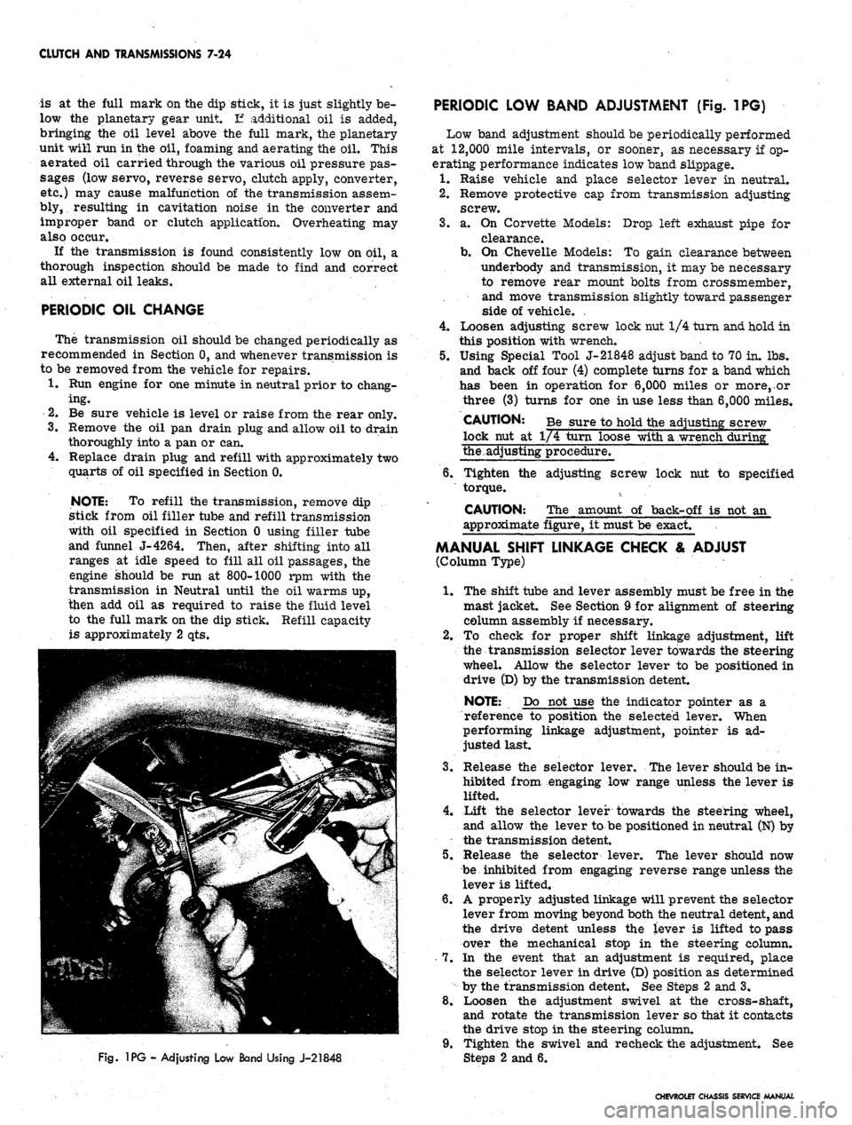
Fig.
1PG - Adjusting Low Band Using J-21848
PERIODIC LOW BAND ADJUSTMENT (Fig. 1PG)
Low band adjustment should be periodically performed
at 12,000 mile intervals, or sooner, as necessary if op-
erating performance indicates low band slippage.
1.
Raise vehicle and place selector lever in neutral.
2.
Remove protective cap from transmission adjusting
screw.
3.
a. On Corvette Models: Drop left exhaust pipe for
clearance.
b.
On Chevelle Models: To gain clearance between
underbody and transmission, it may be necessary
to remove rear mount bolts from crossmember,
and move transmission slightly toward passenger
side of vehicle. .
4.
Loosen adjusting screw lock nut 1/4 turn and hold in
this position with wrench.
5.
Using Special Tool J-21848 adjust band to 70 in. lbs.
and back off four (4) complete turns for a band which
has been in operation for 6,000 miles or more,.or
three (3) turns for one in use less than 6,000 miles.
CAUTION: Be sure to hold the adjusting screw
lock nut at 1/4 turn loose with a wrench during"
the.adjusting procedure.
6. Tighten the adjusting screw lock nut to specified
torque.
CAUTION: The amount of back-off is not an
approximate figure, it must be exact.
MANUAL SHIFT LINKAGE CHECK & ADJUST
(Column Type)
1.
The shift tube and lever assembly must be free in the
mast jacket. See Section 9 for alignment of steering
column assembly if necessary.
2.
To check for proper shift linkage adjustment, lift
the transmission selector lever towards the steering
wheel. Allow the selector lever to be positioned in
drive (D) by the transmission detent.
NOTE: Do not use the indicator pointer as a
reference to position the selected lever. When
performing linkage adjustment, pointer is ad-
justed last.
3.
Release the selector lever. The lever should be in-
hibited from engaging low range unless the lever is
lifted.
4.
Lift the selector lever towards the steering wheel,
and allow the lever to be positioned in neutral (N) by
the transmission detent.
5.
Release the selector lever. The lever should now
be inhibited from engaging reverse range unless the
lever is lifted.
6. A properly adjusted linkage will prevent the selector
lever from moving beyond both the neutral detent, and
the drive detent unless the lever is lifted to pass
over the mechanical stop in the steering column.
7.
In the event that an adjustment is required, place
the selector lever in drive (D) position as determined
by the transmission detent. See Steps 2 and 3.
8. Loosen the adjustment swivel at the cross-shaft,
and rotate the transmission lever so that it contacts
the drive stop in the steering column.
9. Tighten the swivel and recheck the adjustment. See
2 and 6.
CHEVROLET CHASSIS SERVICE MANUAL
Page 569 of 659

ELECTRICAL-BODY AND CHASSIS 12-57
15.
Connect positive lead to battery terminal, lower hood
and test wiper and washer assembly for proper
operation.
WIPER TRANSMISSION
REMOVAL AND INSTALLATION
1.
Remove wiper block and arm assembly from trans-
mission.
2.
Remove glove box door and compartment assembly.
Refer to Section 1 for removal procedures.
3.
Remove three transmission-td-cowl retaining
screws.
4.
Remove wiper transmission retaining clip and re-
move transmission from crank arm. Then remove
transmission through the glove box opening.
5.
Reverse removal procedure to install wiper trans-
mission.
Fig.
94 - Wiper and Trans Installed
WIPER ASSEMBLY REPAIRS
The overhaul procedures for the wiper are broken down
into three major areas: The motor section, gear box
section and washer pump section. Each section may be
serviced independently of the other.
MOTOR SECTION
Disassembly
1.
Remove the two motor tie bolts.
2.
Remove the armature end-play adjusting screw (fig.
91).
3.
Strike the steel case lightly with a mallet to partiaUy
loosen it from the die casting housing and motor
field.
4.
Insert a tool through the armature adjusting screw
opening and push against the end of the armature
shaft to back off the case. This will retain the ar-
mature commutator in position between the brushes
until ready to separate the armature from the case.
5.
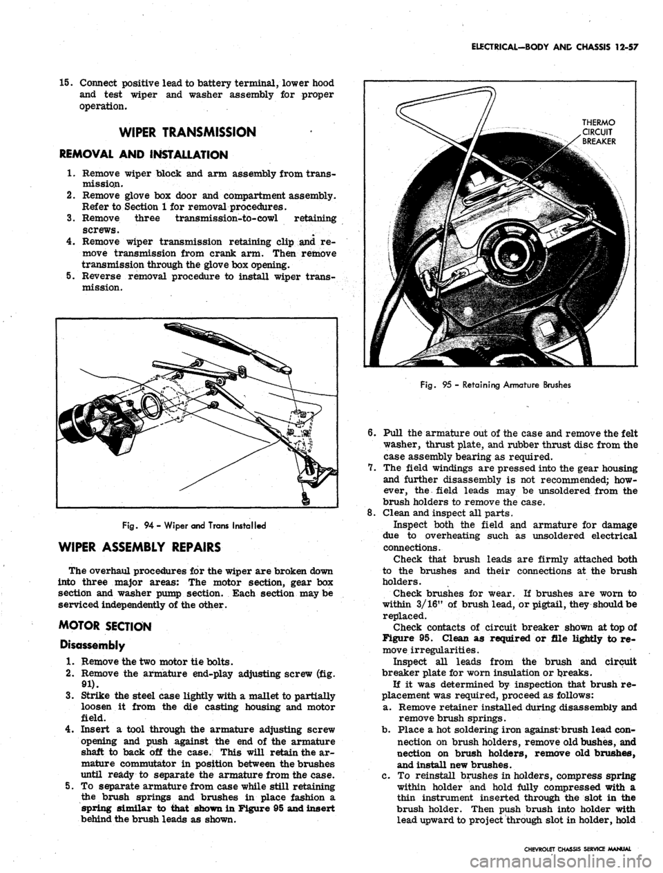
To separate armature from case while still retaining
the brush springs and brushes in place fashion a
spring similar to that shown in Figure 95 and insert
behind the brush leads as shown.
Fig.
95 - Retaining Armature Brushes
6. Pull the armature out of the case and remove the felt
washer, thrust plate, and rubber thrust disc from the
case assembly bearing as required.
7.
The field windings are pressed into the gear housing
and further disassembly is not recommended; how-
ever, the field leads may be unsoldered from the
brush holders to remove the case.
8. Clean and inspect all parts.
Inspect both the field and armature for damage
due to overheating such as unsoldered electrical
connections.
Check that brush leads are firmly attached both
to the brushes and their connections at the brush
holders.
Check brushes for wear. If brushes are worn to
within 3/16" of brush lead, or pigtail, they should be
replaced.
Check contacts of circuit breaker shown at top of
Figure 95. Clean as required or file lightly to re-
move irregularities.
Inspect all leads from the brush and circuit
breaker plate for worn insulation or tjreaks.
If it was determined by inspection that brush re-
placement was required, proceed as follows:
a. Remove retainer installed during disassembly and
remove brush springs.
b.
Place a hot soldering iron against*brush lead con-
nection on brush holders, remove old bushes, and
nection on brush holders, remove old brushes,
and install new brushes.
c. To reinstall brushes in holders, compress spring
within holder and hold fully compressed with a
thin instrument inserted through the slot in the
brush holder. Then push brush into holder with
lead upward to project through slot in holder, hold
CHEVROLET CHASSIS SERVICE MANUAL