sealed beam CHEVROLET CAMARO 1967 1.G Chassis Workshop Manual
[x] Cancel search | Manufacturer: CHEVROLET, Model Year: 1967, Model line: CAMARO, Model: CHEVROLET CAMARO 1967 1.GPages: 659, PDF Size: 114.24 MB
Page 516 of 659
ELECTRICAL-BODY AND CHASSIS 12-4
b.
hand lamp until the string is positioned over the
crossarm centerline. Turn the screw clockwise
in making the final adjustment to take up play in
the headlamp mechanism.
Repeat the above procedure on the right-hand
lamp to complete the horizontal adjustment of the
headlamps.
VERTICAL ADJUSTMENT
8. a. Numeral "2" (fig. 5) should appear in the "down"
window of each aimer. If not, loosen knob at
underside of aimer arm and slide back and forth
until the numeral does appear.
NOTE:
This setting will give a 2" drop of the
headlamp high beam spot centerline on a screen
placed 25 feet forward of the vehicle. Check
state laws for proper vertical setting.
b.
Turn headlamp vertical aim screw (fig. 5) on left-
hand unit counter-clockwise until the bubble is at
the inner end of the glass tube. Then turn screw
clockwise until bubble is centered in tube.
c. Repeat this procedure on right-hand headlamp
unit to complete vertical adjustment of lamps.
9. Recheck the string at the ends of each crossarm for
correct setting and the bubble on each aimer for
centered position.
10.
Remove the aimers by pulling on the suction cup tabs
through the openings in the aimers (fig. 6).
11.
With headlamps properly aimed, replace headlamp
bezels.
HOW TO SELECT A LEVEL AIMING AREA
1.
Select area you believe to be level.
2.
Remove headlamp bezels and install Aimers on each
headlamp (fig. 3) making sure aiming lugs engage
smoooth inner ring of the Aimer.
"
To install Aimer,
press firmly on the knob extending out from the cen-
ter of the Aimer base. This forces the suction cup
into place on the Sealed Beam unit.:
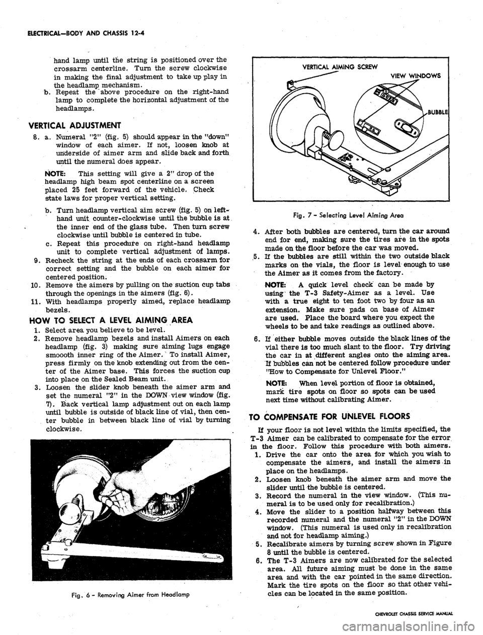
3.
Loosen the slider knob beneath the aimer arm and
set the numeral "2" in the DOWN view window (fig.
7).
Back vertical lamp adjustment out on each lamp
until bubble is outside of black line of vial, then cen-
ter bubble in between black line of vial by turning
clockwise.
VERTICAL AIMING SCREW
VIEW WINDOWS
BUBBLE
Fig.
6 - Removing Aimer from Headlamp
Fog.
7- Selecting Level Aiming Area
4.
After botli bubbles are centered, turn the car around
end for end, making sure the tires are in the spots
made on the floor before the car was moved.
.5.
If the bubbles are still within the two outside black
marks on the vials, the floor is level enough to use
the Aimer as it comes from the factory.
NOTE:
A quick level check can be made by
using the T-3 Safety-Aimer as a level. Use
with a true eight to ten foot two by four as an
extension. Make sure pads on base of Aimer
are used. Place the board where you expect the
wheels to be and take readings as outlined above.
6. If either bubble moves outside the black lines of the
vial there is too much slant to the floor. Try driving
the car in at different angles onto the aiming area.
If bubbles can
not
be centered follow procedure under
"How to Compensate for Unlevel Floor."
NOTE:
When level portion of floor is obtained,
mark tire spots on floor so spots can be used
next time without calibrating Aimer.
TO COMPENSATE FOR UNLEVEL FLOORS
If your floor is not level within the limits specified, the
T-3 Aimer can be calibrated to compensate for the error
in the floor. Follow this procedure with both aimers.
1.
Drive the car onto the area for which you wish to
compensate the aimers, and install the aimers in
place on the headlamps.
2.
Loosen knob beneath the aimer arm and move the
slider until the bubble is centered.
3.
Record the numeral in the view window. (This nu-
meral is to be used only for recalibration.)
4.
Move the slider to a position halfway between this
recorded numeral and the numeral "2" in the
DOWN
window. (This numeral is used only in recalibration
and not for headlamp aiming.)
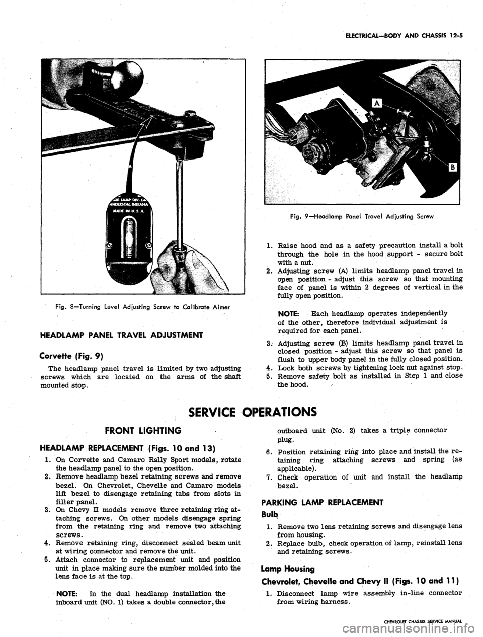
5.
Recalibrate aimers by turning screw shown in Figure
8 until the bubble is centered.
6. The T-3 Aimers are now calibrated for the selected
area. All future aiming must be done in the same
area and with the car pointed in the same direction.
Mark the tire spots on the floor so that other vehi-
cles can be located in the same position.
CHEVROLET CHASSIS SERVICE MANUAL
Page 517 of 659
ELECTRICAL-BODY AND CHASSIS 12-5
Fig.
8—Turning Level Adjusting Screw to Calibrate Aimer
HEADLAMP PANEL TRAVEL ADJUSTMENT
Corvette (Fig. 9)
The headlamp panel travel is limited by two adjusting
screws which are located on the arms of the shaft
mounted stop.
Fig.
9—Headlamp Panel Travel Adjusting Screw
1.
Raise hood and as a safety precaution install a bolt
through the hole in the hood support - secure bolt
with a nut.
2.
Adjusting screw (A) limits headlamp panel travel in
open position - adjust this screw so that mounting
face of panel is within 2 degrees of vertical in the
fully open position.
NOTE: Each headlamp operates independently
of the other, therefore individual adjustment is
required for each panel.
3.
Adjusting screw (B) limits headlamp panel travel in
closed position - adjust this screw so that panel is
flush to upper body panel in the fully closed position.
4.
Lock both screws by tightening lock nut against stop.
5.
Remove safety bolt as installed in Step 1 and close
the hood.
SERVICE OPERATIONS
FRONT LIGHTING
HEADLAMP REPLACEMENT (Figs. 10 and 13)
1.
On Corvette and Camaro Rally Sport models, rotate
the headlamp panel to the open position.
2.
Remove headlamp bezel retaining screws and remove
bezel. On Chevrolet, Chevelle and Camaro models
lift bezel to disengage retaining tabs from slots in
filler panel.
3.
On Chevy n models remove three retaining ring at-
taching screws. On other models disengage spring
from the retaining ring and remove two attaching
screws.
4.
Remove retaining ring, disconnect sealed beam unit
at wiring connector and remove the unit.
5.
Attach connector to replacement unit and position
unit in place making sure the number molded into the
lens face is at the top.
NOTE: In the dual headlamp installation the
inboard unit (NO. 1) takes a double connector, the
outboard unit (No. 2) takes a triple connector
plug.
6. Position retaining ring into place and install the re-
taining ring attaching screws and spring (as
applicable).
7.
Check operation of unit and install the headlamp
bezel.
PARKING LAMP REPLACEMENT
Bulb
1.
Remove two lens retaining screws and disengage lens
from housing.
2.
Replace bulb, check operation of lamp, reinstall lens
and retaining screws.
Lamp Housing
Chevrolet, Chevelle and Chevy II (Figs. 10 and 11)
1.
Disconnect lamp wire assembly in-line connector
from wiring harness.
CHEVROLET CHASSIS SERVICE MANUAL
Page 520 of 659
ELECTRICAL-BODY AND CHASSIS 12-8
is inserted through radiator support opening.
Remove two screws retaining lamp assembly to
lower sheet metal.
Remove three screws retaining lamp assembly to
lender.
To replace lamp assembly, reverse removal proce-
dure and check operation of the unit.
is aligned with flat on pivot shaft. Install stop lock
bolt and torque bolt to 45-60 in, lbs. Make sure that
side-to-side panel alignment is not changed when in-
stalling and tightening the stop.
CAUTION: Do not exceed specified torque
when tightening stop lock bolt.
HEADLAMP PANEL REPLACEMENT-CORVETTE
Refer to Figure 13 for Panel Mounting details.
1.
Remove engine compartment hood as outlined in
Section 1.
2.
Actuate headlamp panel to the open position.
NOTE:
In the event headlamp motor is inop-
erative, manual positioning of the panel can be
accomplished by turning the knurled knob at in-
board end of motor. As an assist in manual
operation of panel, apply light hand pressure to
panel in desired direction of rotation.
3.
Remove positive lead from battery terminal.
4.
Remove headlamp bezel retaining screws and bezel.
5. Remove the sealed beam housing unit as an assem-
bly - disconnect sealed beam leads at harness con-
nector and remove connector from sealed beam
leads;
remove the housing-to-panel retaining screws
and remove housing unit and wiring from panel.
6. Remove motor from panel pivot shaft - see motor
removal procedure. Then remove the panel stop
from panel inboard pivot shaft, and disconnect switch
lead wires from panel, support-mounted motor
switch.
7. Remove the panel retaining bolt access hole plugs
from inside the panel then rotate panel as required
and remove the retaining bolts and slide supports
from ends of panel pivot shaft. Remove bearing, felt
seal, retainer and washer from inboard pivot shaft.
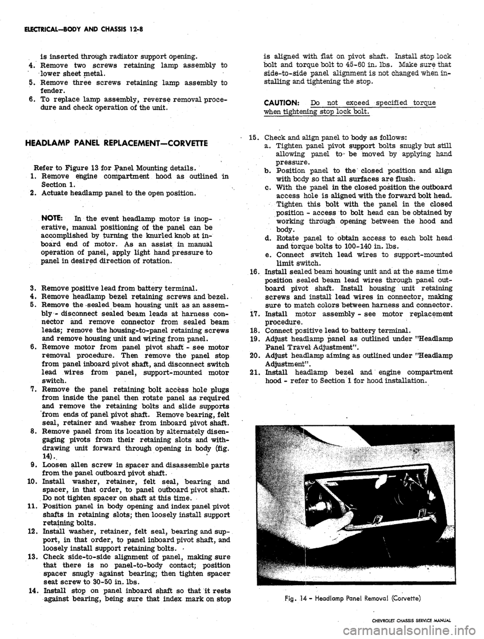
8. Remove panel from its location by alternately disen-
gaging pivots from their retaining slots and with-
drawing unit forward through opening in body (fig.
14).
9. Loosen alien screw in spacer and disassemble parts
from the panel outboard pivot shaft.
10.
Install washer, retainer, felt seal, bearing and
spacer, in that order, to panel outboard pivot shaft.
Do not tighten spacer on shaft at this time.
11.
Position panel in body opening and index panel pivot
shafts in retaining slots; then loosely install support
retaining bolts.
12.
Install washer, retainer, felt seal, bearing and sup-
port, in that order, to panel inboard pivot shaft, and
loosely install support retaining bolts. -
13.
Check side-to-side alignment of panel, making sure
that there is no panel-to-body contact; position
spacer snugly against bearing; then tighten spacer
seat screw to 30-50 in. lbs.
14.
Install stop on panel inboard shaft so that it rests
against bearing, being sure that index mark on stop
15.
Check and align panel to body as follows:
a. Tighten panel pivot support bolts snugly but still
allowing panel to" be moved by applying hand
pressure.
b.
Position panel to the closed position and align
with body so that all surfaces are flush.
c. With the panel in the closed position the outboard
access hole is aligned with the forward bolt head.
Tighten this bolt with the panel in the closed
position - access to bolt head can be obtained by
working through opening between the hood and
body.
d. Rotate panel to obtain access to each bolt head
and torque bolts to 100-140 in. lbs.
e. Connect switch lead wires to support-mounted
limit switch.
16.
Install seaLed beam housing unit and at the same time
position sealed beam lead wires through panel out-
board pivot shaft. Install housing unit retaining
screws and install lead wires in connector, making
sure to match colors between harness and connector.
17.
Install motor assembly - see motor replacement
procedure.
18.
Connect positive lead to battery terminal.
19.
Adjust headlamp panel as outlined under "Headlamp
Panel Travel Adjustment".
20.
Adjust headlamp aiming as outlined under "Headlamp
Adjustment".
21.
Install headlamp bezel and engine compartment
hood - refer to Section 1 for hood installation.
Fig.
14
- Headlamp Panel Removal (Corvette)
CHEVROLET CHASSIS SERVICE MANUAL