boot CHEVROLET CAMARO 1982 Repair Guide
[x] Cancel search | Manufacturer: CHEVROLET, Model Year: 1982, Model line: CAMARO, Model: CHEVROLET CAMARO 1982Pages: 875, PDF Size: 88.64 MB
Page 112 of 875

GM – CAMARO 1982-1992 – Repair Guide (Checked by WxMax) 112
4. Position a C-clamp a
nd tighten until the piston bottoms in the base of the
caliper housing. Make sure 1 end of the C-clamp rests on the inlet fitting bolt
and the other against the outboard disc brake pad.
It is not necessary to remove the parki ng brake caliper lever return spring to
replace the disc brake pads.
5. Remove the upper caliper guide pin bolt and discard.
6. Rotate the caliper housing. Be careful not to strain the hose or cable conduit.
7. Remove the disc brake pads.
To install:
8. Clean all residue from the pad guide surfaces on the mounting bracket and
caliper housing. Inspect the guide pins for free movement in the mounting
bracket. Replace the guide pins or boot s, if they are corroded or damaged.
9. Install the disc brake pads. The out board pad with insulator is installed
toward the caliper housing. The inboard pad with the w ear sensor is installed
nearest the caliper piston. The wear sens or must be in the trailing position
with forward wheel rotation.
10. Rotate the caliper housing into it 's operating position. The springs on the
outboard brake pad must not stick through the inspection hole in the caliper
housing. If the springs are sticking thr ough the inspection hole in the caliper
housing, lift the caliper housing and make the necessary corrections to the
outboard brake pad positions.
11. Install a new upper cali per guide pin bolt and tight en to 26 ft. lbs. (35 Nm).
Tighten the lower caliper guide pin bolt to 16 ft. lbs. (22 Nm).
12. With the engine runni ng, pump the brake pedal slo wly and firmly to seat the
brake pads.
13. Check the caliper parking brake levers to make sure they are against the
stops on the caliper housing. If the leve rs are not on their stops, check the
parking brake adjustment.
14. Remove the 2 wheel nuts from t he rotor and install the wheel and tire
assembly.
15. Lower the vehicle, che ck the master cylinder fluid level and road test the
vehicle.
BRAKE CALIPER
REMOVAL & INSTALLATION
CAUTION - Brake pads contain asbestos, which has been determined to be a
cancer causing agent. Never clean the brake surfaces with compressed air!
Avoid inhaling any dust from any brake surface! When cleaning brake surfaces,
use a commercially available brake cleaning fluid.
1982-88 MODELS
Page 114 of 875
GM – CAMARO 1982-1992 – Repair Guide (Checked by WxMax) 114
9. Inspect the guide pins and boots and re
place if corroded, worn or damaged.
Check the inlet fitting bolt for blockage.
10. Install the caliper housing over t he rotor and into the mounting bracket.
Install the 2 caliper guide pin bolts. Tighten the upper caliper guide pin bolt
to 26 ft. lbs. (35 Nm) and the lower gui de pin bolt to 16 ft. lbs. (22 Nm).
11. Connect the parking brake cable to t he caliper bracket and caliper lever.
Install the caliper lever return spring, if removed.
12. Install the inlet fitting, bolt and 2 new washers to the caliper housing. Tighten
the bolt to 22 ft. lbs. (30 Nm).
13. Bleed the brake system.
14. Adjust the parking brake free trav el if the caliper was overhauled.
15. Lower the vehicle and cycle the parking brake.
16. Raise and safely support the vehicle.
17. Inspect the caliper parking brake levers and ensure they are against the
stops on the caliper housing. If the levers are not on their stop, refer to the
parking brake adjustment.
18. Remove the 2 nuts securing the roto r and then install the wheel and tire
assembly. Lower the vehicle.
19. With the engine running, pump the br ake pedal slowly and firmly 3 times to
seat the disc brake pads. Check the hydraulic system for leaks.
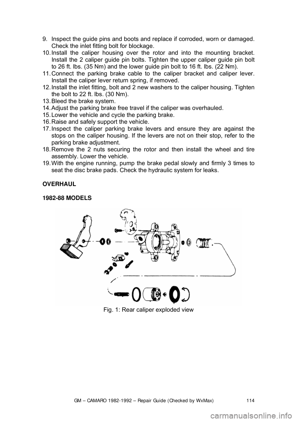
OVERHAUL
1982-88 MODELS
Fig. 1: Rear caliper exploded view
Page 115 of 875
GM – CAMARO 1982-1992 – Repair Guide (Checked by WxMax) 115
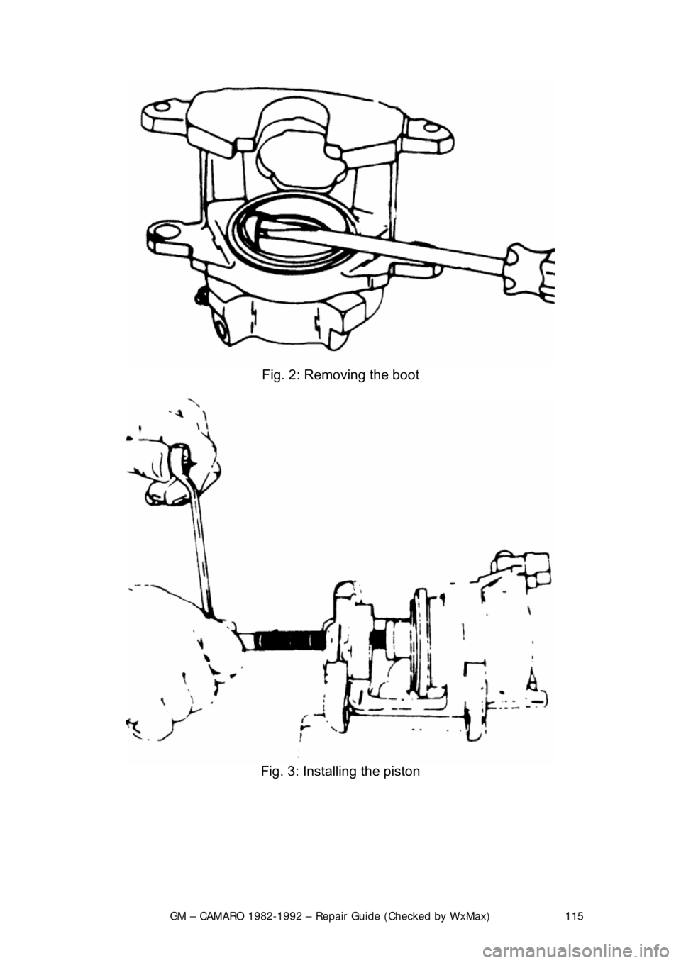
Fig. 2: Removing the boot
Fig. 3: Installing the piston
Page 116 of 875
GM – CAMARO 1982-1992 – Repair Guide (Checked by WxMax) 116
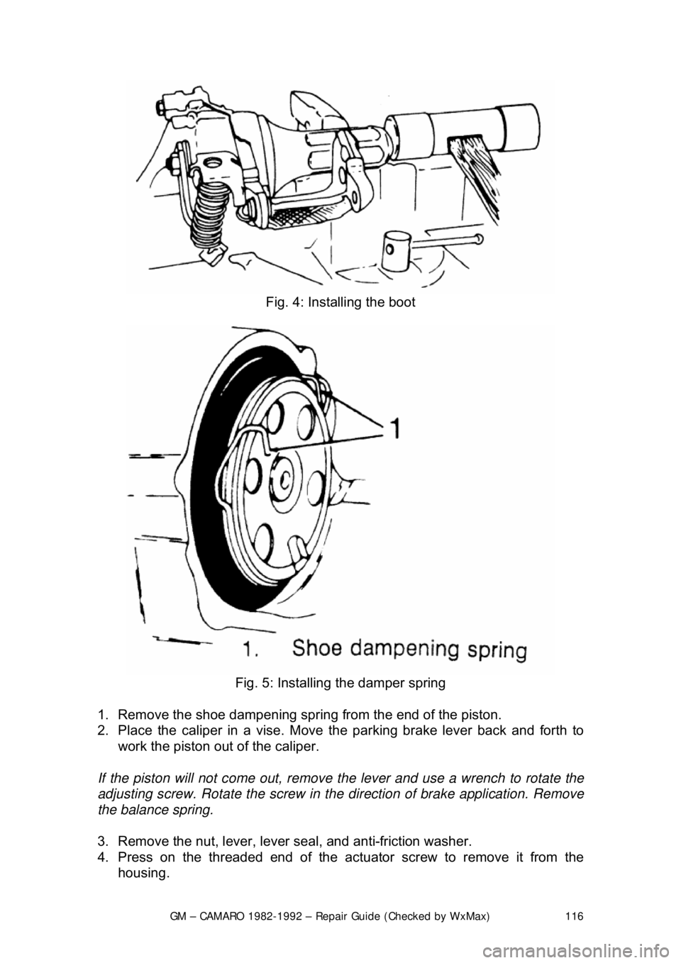
Fig. 4: Installing the boot
Fig. 5: Installing the damper spring
1. Remove the shoe dampening spring from the end of the piston.
2. Place the caliper in a vise. Move the parking brake lever back and forth to
work the piston out of the caliper.
If the piston will not come out, remove the lever and use a wrench to rotate the
adjusting screw. Rotate the screw in t he direction of brake application. Remove
the balance spring.
3. Remove the nut, lever, lever seal, and anti-friction washer.
4. Press on the threaded end of the act uator screw to remove it from the
housing.
Page 117 of 875

GM – CAMARO 1982-1992 – Repair Guide (Checked by WxMax) 117
5. Remove the shaft seal and washer.
6. Remove the dust boot. Be careful not to scratch the housing bore.
7. Remove the locator retainer if so
equipped. Remove the piston locator if so
equipped.
8. Remove the piston seal usi ng a wooden or plastic tool.
9. Remove the bleeder screw, bolt, fi tting, and copper washer. Remove the
bracket only if it is damaged.
10. Inspect caliper bore for scoring, nicks, corrosion, and wear. Use crocus cloth
for light corrosion. Replace caliper if bore will not clean up.
To install:
11. Replace the bleeder screw, bolt, fitting, and copper washer.
12. Install the piston. Lubricate seal s and piston with brake fluid prior to
reinstallation.
13. Install the locator retainer if so equi pped. Install the piston locator if so
equipped.
14. Install the dust boot.
15. Install the shaft seal and washer.
16. Install actuator scr ew to the housing.
17. Install the nut, lever, lever seal, and anti-friction washer. It may be necessary
to rotate the parking brake lever away from the stop to install the nut. Torque
the nut 30-40 ft. lbs. (41-54 Nm) and ro tate the lever back to the stop.
18. Install the shoe dampening spri ng to the end of the piston.
It may be necessary to move the parking brake lever off the stop, extending the
piston slightly, making the dampening spring groove acce ssible. If the piston is
extended, push it back into the caliper before installing the caliper on the car.
1989-92 MODELS
1. Remove the caliper assembly. Remove the 2 collar return springs from the
actuating collar. Remove the actuator collar assembly with parts attached
out of the housing.
2. Remove the clamp rod and compliance bushing.
3. Remove the boot retainers, 2 boots and pushrod from the compliance
bushing. Discard the retainers and boots.
4. Remove the preload spring from the retainer.
5. Using compressed air directed into the brake hose port, carefully extract
piston.
CAUTION - Do not place fingers between piston and brake shoe flange, or
personal injury may occur when piston breaks free from bore. Cover caliper
assembly with a rag to prevent brake fluid from spraying when piston is
extracted
6. Inspect and clean piston and bore a ssembly for cracks or scoring.
7. Remove the piston seal.
8. Remove the bleeder valve.
Page 118 of 875

GM – CAMARO 1982-1992 – Repair Guide (Checked by WxMax) 118
9. Remove the caliper lever pivot pin s
eal, sprag clip, spring and lever. Discard
the clip.
10. Inspect the caliper lever for worn spots, replace as necessary.
11. Remove the 2 guide pins from the mounting bracket.
12. Clean all parts not included in the r ebuild kit in denatured alcohol. Use only
dry filtered compressed air to dry parts . Replace the caliper housing if badly
scored or corroded.
To install:
13. Lubricate the new piston s eal with clean brake fluid. Place the seal into the
caliper groove, making sure t he seal is not twisted.
14. Install the piston. Lubricate seal s and piston with brake fluid prior to
reinstallation.
15. Assemble the pushrod, 2 new boots and new retainers to the actuating
collar.
16. Lightly coat the actuat ing collar with the lubricant provided in the rebuild kit.
Do not use any other type of lubricant.
17. Install the clamp retainers firmly agains t the actuating collar. Bend the tabs
on the retainer to hold the assembly together.
18. Install the preload spring into the boot retainers.
19. Install the clamp rod to the actuati ng collar and boot. Lubricate the clamp rod
with the lubricant supplied in the kit.
20. Slide the clamp rod th rough the holes in the boot and actuating collar. The
boot must be against the reacti on plate on the clamp rod.
21. Lubricate and install t he new compliance bushing with the lubricant supplied
in the kit.
22. Install the clamp rod with assembled parts into the connecting hole in the
caliper piston.
23. Install a new bleeder valve.
24. Install the pivot pin and new nut into the housing, if removed.
25. Install the caliper pivot pin seal, parking brake lever, new sprag clip and
spring, in that order. The teeth of the sprag clip mu st face away from the
lever.
26. Install the 2 collar return springs to the retainer. The retainer must enter the
return springs at the end of the second coil.
27. Install the adjuster screw into the cali per housing until the actuating collar is
parallel to the piston bore face of the caliper housing.
28. Lubricate and then install the guide pi ns and boots. Install the pads and
caliper assembly.
29. Bleed the brake system.
BRAKE DISC (ROTOR)
REMOVAL & INSTALLATION
CAUTION - Brake pads contain asbestos, which has been determined to be a
cancer causing agent. Never clean the brake surfaces with compressed air!
Avoid inhaling any dust from any brake surface! When cleaning brake surfaces,
use a commercially available brake cleaning fluid.
Page 135 of 875
GM – CAMARO 1982-1992 – Repair Guide (Checked by WxMax) 135
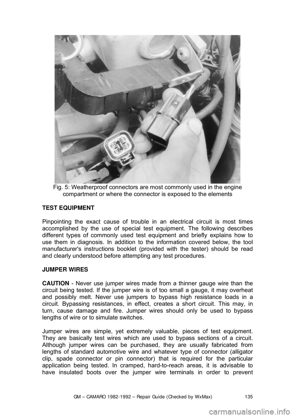
Fig. 5: Weatherproof connectors ar e most commonly used in the engine
compartment or where the connecto r is exposed to the elements
TEST EQUIPMENT
Pinpointing the exact cause of trouble in an electrical circuit is most times
accomplished by the use of special te st equipment. The following describes
different types of commonly used test eq uipment and briefly explains how to
use them in diagnosis. In addition to t he information covered below, the tool
manufacturer's instructions booklet (pro vided with the tester) should be read
and clearly understood before atte mpting any test procedures.
JUMPER WIRES
CAUTION - Never use jumper wires made from a thinner gauge wire than the
circuit being tested. If the jumper wire is of too small a gauge, it may overheat
and possibly melt. Never use jumpers to bypass high resistance loads in a
circuit. Bypassing resistances, in effect, cr eates a short circuit. This may, in
turn, cause damage and fire. Jumper wi res should only be used to bypass
lengths of wire or to simulate switches.
Jumper wires are simple, yet extremel y valuable, pieces of test equipment.
They are basically test wir es which are used to bypass sections of a circuit.
Although jumper wires can be purchased, they are usually fabricated from
lengths of standard automot ive wire and whatever type of connector (alligator
clip, spade connector or pin connector) that is required for the particular
application being tested. In cramped, hard- to-reach areas, it is advisable to
have insulated boots over the jumper wire terminals in order to prevent
Page 291 of 875

GM – CAMARO 1982-1992 – Repair Guide (Checked by WxMax) 291
6. Remove the console cover.
7. Remove the shifter boot.
8. Remove the shifter mounting bolt
s and remove the shifter assembly.
9. Installation is the reverse of the removal procedure. Adjust the linkage as
detailed earlier.
BACK-UP LIGHT SWITCH
REMOVAL & INSTALLATION 1. Disconnect the negative battery terminal from the battery.
2. At the left-rear of the transmission, the back-up light switch is threaded
into the transmission case. The speed sensor is held in with a separate
bracket. Disconnect the electrical co nnector from the back-up light
switch.
3. Remove the back-up light swit ch from the transmission.
4. To install, reverse the remova l procedures. Coat the threads with
Teflon® tape. Please refer to the to rque chart for specifications. Place
the gear shift lever in the revers e position and check that the back-up
lights work.
EXTENSION HOUSING SEAL
REMOVAL & INSTALLATION
This seal controls transmission oil leakage around the driveshaft. Continued
failure of this seal usually indicates a worn output shaft bushing. If so, there will
be signs of the same wear on the driveshaft where it contacts the seal and
bushing. The seal is available and is fairly simple to install, with the proper tool.
1. Raise and safely support the rear of the vehicle to minimize transmission
oil loss when the driveshaft is removed.
2. Unbolt the driveshaft fr om the differential and center support bearing, if
equipped. Wrap tape around the bearing cu ps to keep them in place on
the universal joint and slide the sh aft out of the transmission.
3. Use an small pry tool to carefully pry out the old seal. Be careful not to
insert the tool too far into the hous ing or the bushing will be damaged.
Page 292 of 875
GM – CAMARO 1982-1992 – Repair Guide (Checked by WxMax) 292
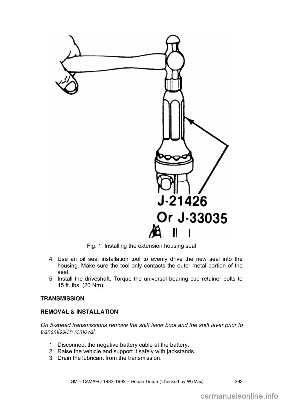
Fig. 1: Installing the extension housing seal
4. Use an oil seal installation tool to evenly drive the new seal into the
housing. Make sure the tool only cont acts the outer metal portion of the
seal.
5. Install the driveshaft. Torque the uni versal bearing cup retainer bolts to
15 ft. lbs. (20 Nm).
TRANSMISSION
REMOVAL & INSTALLATION
On 5-speed transmissions remove the shif t lever boot and the shift lever prior to
transmission removal.
1. Disconnect the negative batte ry cable at the battery.
2. Raise the vehicle and support it safely with jackstands.
3. Drain the lubricant from the transmission.
Page 299 of 875
GM – CAMARO 1982-1992 – Repair Guide (Checked by WxMax) 299
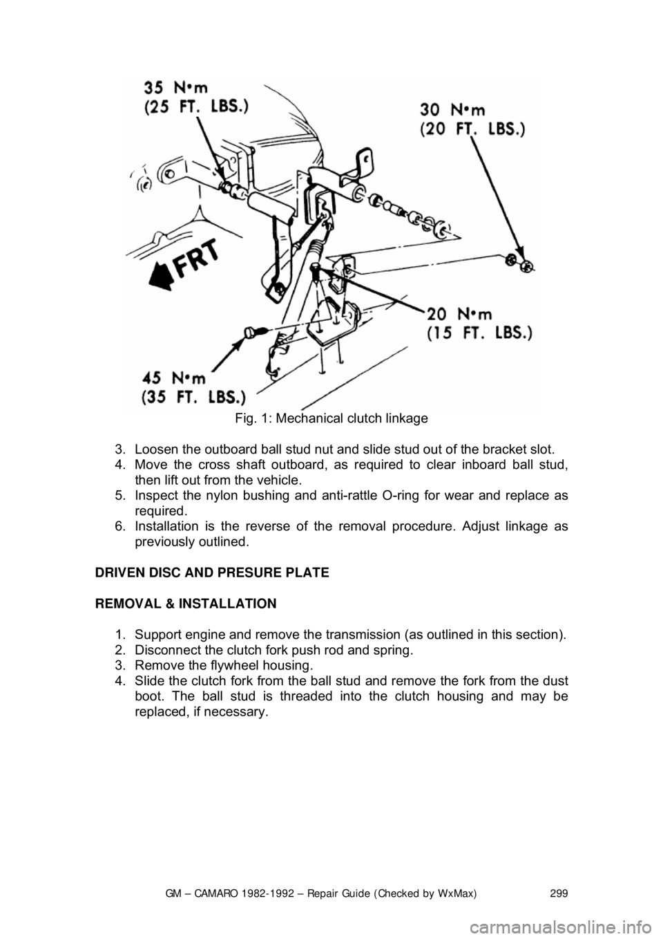
Fig. 1: Mechanical clutch linkage
3. Loosen the outboard ball stud nut and slid e stud out of the bracket slot.
4. Move the cross shaft outboard, as required to clear inboard ball stud,
then lift out from the vehicle.
5. Inspect the nylon bushing and anti-ra ttle O-ring for wear and replace as
required.
6. Installation is the reverse of th e removal procedure. Adjust linkage as
previously outlined.
DRIVEN DISC AND PRESURE PLATE
REMOVAL & INSTALLATION 1. Support engine and remove the transmissi on (as outlined in this section).
2. Disconnect the clutch fork push rod and spring.
3. Remove the flywheel housing.
4. Slide the clutch fork from the ball stud and remove the fork from the dust
boot. The ball stud is threaded into the clutch housing and may be
replaced, if necessary.