boot CHEVROLET CAMARO 1982 Repair Guide
[x] Cancel search | Manufacturer: CHEVROLET, Model Year: 1982, Model line: CAMARO, Model: CHEVROLET CAMARO 1982Pages: 875, PDF Size: 88.64 MB
Page 48 of 875

GM – CAMARO 1982-1992 – Repair Guide (Checked by WxMax) 48
BRAKES
BASIC OPERATING PRINCIPLES
Hydraulic systems are used to actuate t he brakes of all modern automobiles.
The system transports the power required to force the frictional surfaces of the
braking system together from the pedal to the individual brake units at each
wheel. A hydraulic system is used for two reasons.
First, fluid under pressure can be carried to all parts of an automobile by small
pipes and flexible hoses without taking up a significant amount of room or
posing routing problems.
Second, a great mechanical advantage can be given to the brake pedal end of
the system, and the foot pressure requi red to actuate the brakes can be
reduced by making the surface area of t he master cylinder pistons smaller than
that of any of the pistons in t he wheel cylinders or calipers.
The master cylinder consists of a flui d reservoir along with a double cylinder
and piston assembly. Double type master cylinders are designed to separate
the front and rear braking systems hydraulic ally in case of a leak. The master
cylinder coverts mechanical motion from t he pedal into hydraulic pressure within
the lines. This pressure is translated back into mechanical motion at th\
e wheels
by either the wheel cylinder (drum brak es) or the caliper (disc brakes).
Steel lines carry the brake fluid to a po int on the vehicle's frame near each of
the vehicle's wheels. The fluid is then ca rried to the calipers and wheel cylinders
by flexible tubes in order to allow for suspension and steering movements.
In drum brake systems, each wheel cylinde r contains two pistons, one at either
end, which push outward in opposite direct ions and force the brake shoe into
contact with the drum.
In disc brake systems, the cylinders ar e part of the calipers. At least one
cylinder in each caliper is used to fo rce the brake pads against the disc.
All pistons employ some type of seal, us ually made of rubber, to minimize fluid
leakage. A rubber dust boot seals the outer end of the cylinder against dust and
dirt. The boot fits around the outer end of the piston on disc brake calipers, and
around the brake actuating rod on wheel cylinders.
The hydraulic system operates as follows : When at rest, the entire system, from
the piston(s) in the master cylinder to t hose in the wheel cylinders or calipers, is
full of brake fluid. Upon app lication of the brake pedal, fluid trapped in front of
the master cylinder piston(s) is forced through the lines to the wheel cylinders.
Here, it forces the pistons outward, in the case of drum brakes, and inward
toward the disc, in the case of disc brakes. The motion of the pistons is
opposed by return springs mounted outside the cylinders in drum brakes, and
by spring seals, in disc brakes.
Page 57 of 875
GM – CAMARO 1982-1992 – Repair Guide (Checked by WxMax) 57
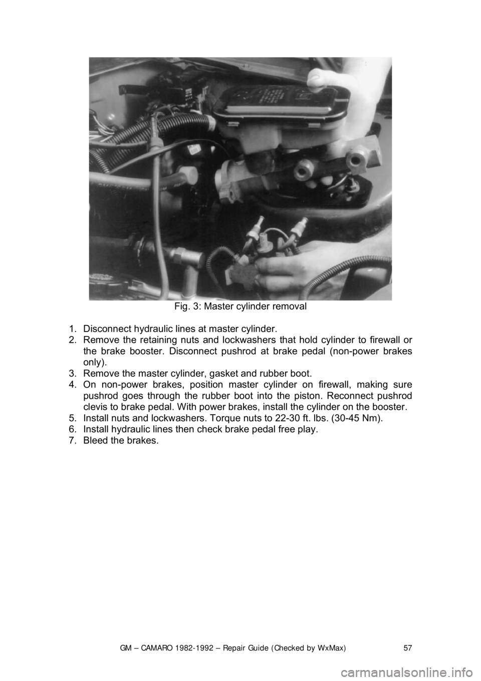
Fig. 3: Master cylinder removal
1. Disconnect hydraulic lines at master cylinder.
2. Remove the retaining nuts and lockwasher s that hold cylinder to firewall or
the brake booster. Disconnect pushrod at brake pedal (non-power brakes
only).
3. Remove the master cylinder, gasket and rubber boot.
4. On non-power brakes, position master cylinder on firewall, making sure pushrod goes through the rubber boot in to the piston. Reconnect pushrod
clevis to brake pedal. With power brakes, install the cylinder on the bo\
oster.
5. Install nuts and lockwashers. Torque nut s to 22-30 ft. lbs. (30-45 Nm).
6. Install hydraulic lines t hen check brake pedal free play.
7. Bleed the brakes.
Page 82 of 875

GM – CAMARO 1982-1992 – Repair Guide (Checked by WxMax) 82
Avoid inhaling any dust from
any brake surface! When cleaning brake surfaces,
use a commercially available brake cleaning fluid.
1. Remove
2/3 of the brake fluid from the mast er cylinder. Raise the vehicle and
remove the wheel.
2. Place a C-clamp across the caliper, positioned on the brake pads. Tighten it
until the piston is forced into its bore.
3. Remove the C-clamp. Remove the bolt holding the brake hose to the caliper.
4. Remove the Allen head caliper mounting bolts. Inspect them for corrosion
and replace them if necessary. Remove the caliper.
To install:
5. Position the caliper with the brake pad installed and install Allen head caliper
mounting bolts. Mounting bo lt torque is 21-35 ft. lbs. (28-47 Nm.) for the
caliper.
6. Install the bolt holding the brake hos e to the caliper and tighten to 18-30 ft.
lbs. (24-40 Nm.).
7. Fill the master cylinder with brake fluid.
8. Install the wheels and lower the vehicle.
CAUTION - Before moving the vehicle, pump the brakes several times to seat
the brake pad against the rotor
OVERHAUL
Some vehicles may be equipped dual piston calipers. The procedure to
overhaul the caliper is e ssentially the same with t he exception of multiple
pistons, O-rings and dust boots.
1. Remove the caliper from the ve hicle and place on a clean workbench.
CAUTION - NEVER place your finger s in front of the pistons in an attempt to
catch or protect the pistons when applying compressed air. This could result in
personal injury!
Depending upon the vehicle, there are two different ways to remove the piston
from the caliper. Refer to the brake pad replacement procedure to make sure
you have the correct procedure for your vehicle.
2. The first method is as follows: a. Stuff a shop towel or a block of wood into the caliper to catch the piston.
b. Remove the caliper piston using co mpressed air applied into the caliper
inlet hole. Inspect the piston for scor ing, nicks, corrosion and/or worn or
damaged chrome plating. The piston mu st be replaced if any of these
conditions are found.
Page 84 of 875
GM – CAMARO 1982-1992 – Repair Guide (Checked by WxMax) 84
3. For the second method, you must rota
te the piston to retract it from the
caliper.
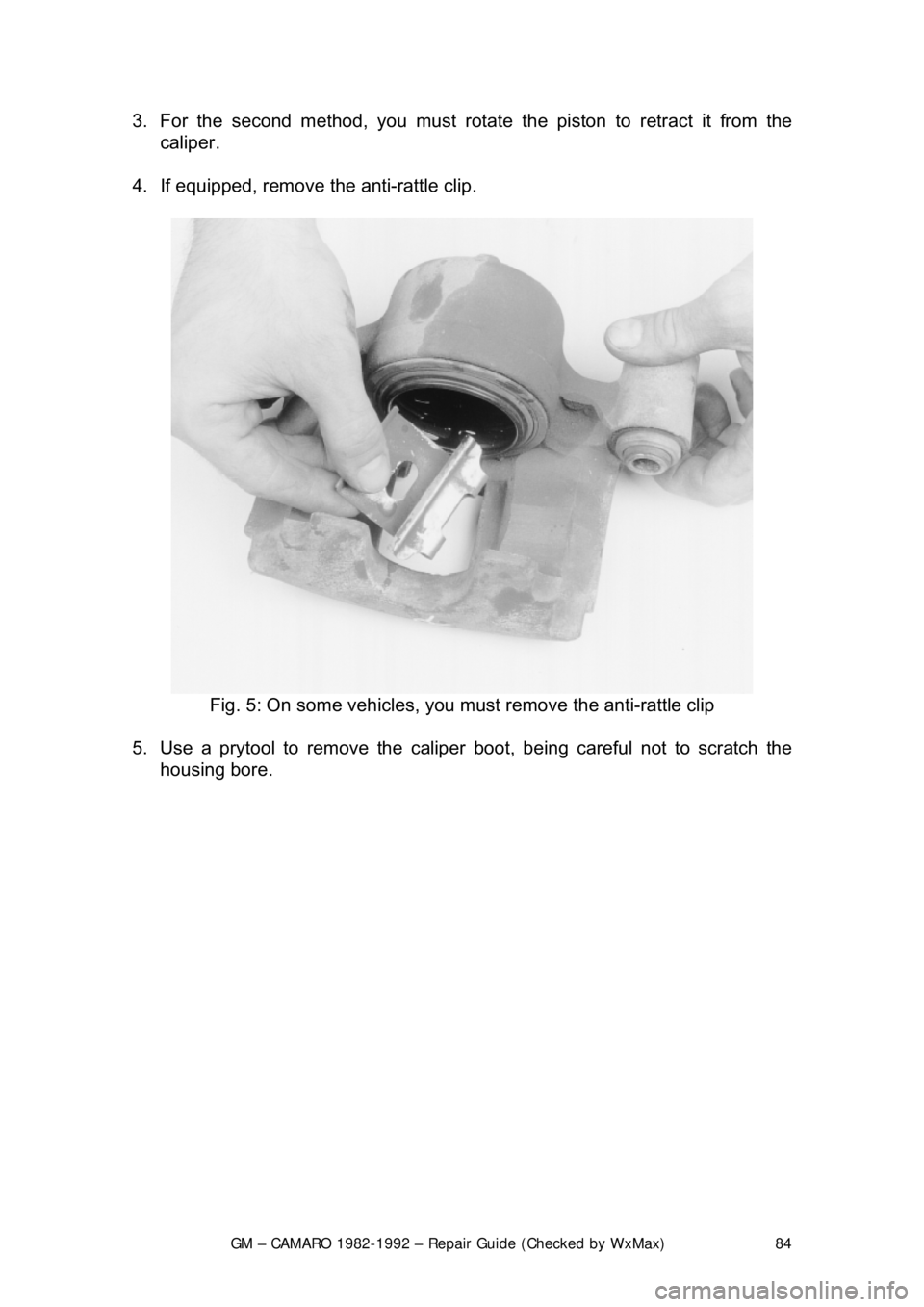
4. If equipped, remove th e anti-rattle clip.
Fig. 5: On some vehicles, you must remove the anti-rattle clip
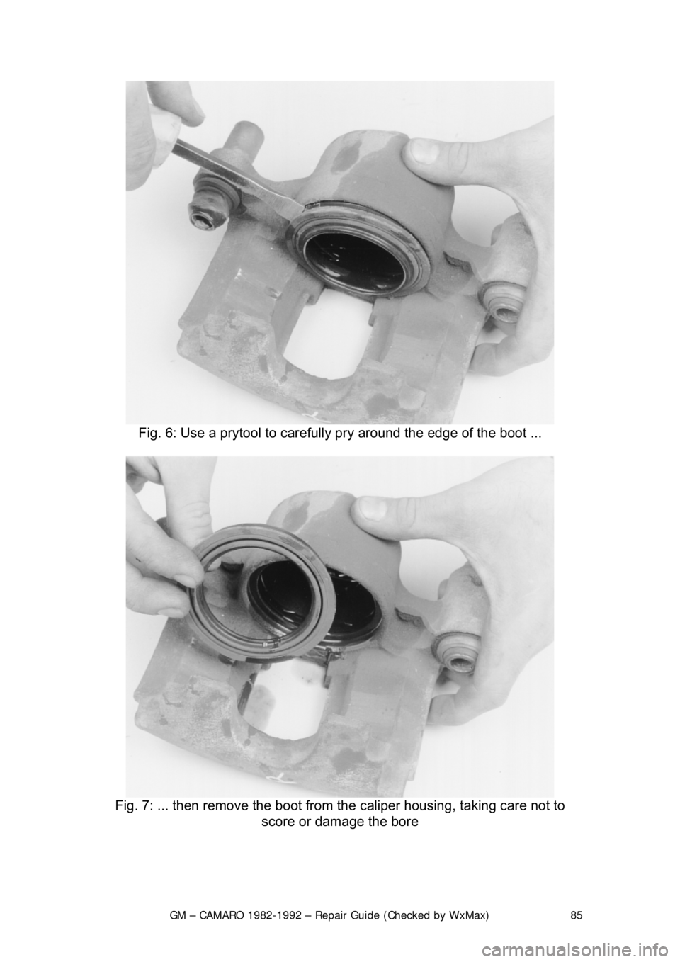
5. Use a prytool to remove the caliper boot, being careful not to scratch the
housing bore.
Page 85 of 875
GM – CAMARO 1982-1992 – Repair Guide (Checked by WxMax) 85
Fig. 6: Use a prytool to carefully pry around the edge of the boot ...
Fig. 7: ... then remo ve the boot from the caliper housing, taking care not to
score or damage the bore
Page 86 of 875
GM – CAMARO 1982-1992 – Repair Guide (Checked by WxMax) 86
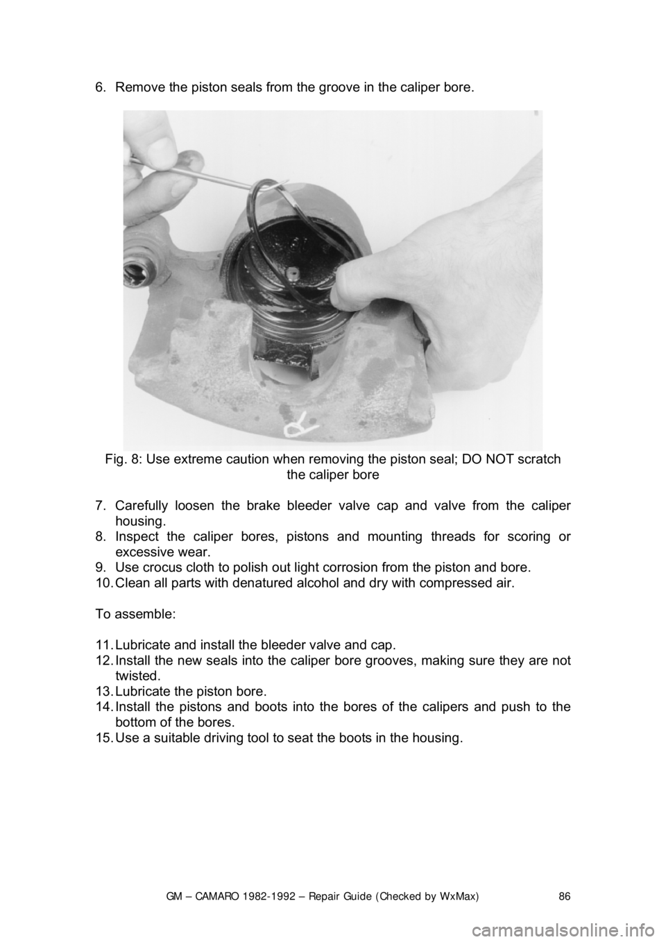
6. Remove the piston seals from
the groove in the caliper bore.
Fig. 8: Use extreme caution when remo ving the piston seal; DO NOT scratch
the caliper bore
7. Carefully loosen the br ake bleeder valve cap and valve from the caliper
housing.
8. Inspect the caliper bores, pistons and mounting threads for scoring or excessive wear.
9. Use crocus cloth to polish out light corrosion from the piston and bore.
10. Clean all parts with denatured alcohol and dry with compressed air.
To assemble:
11. Lubricate and install th e bleeder valve and cap.
12. Install the new seals into the caliper bore grooves, making sure they are not
twisted.
13. Lubricate the piston bore.
14. Install the pistons and boots into the bores of the calipers and push to the
bottom of the bores.
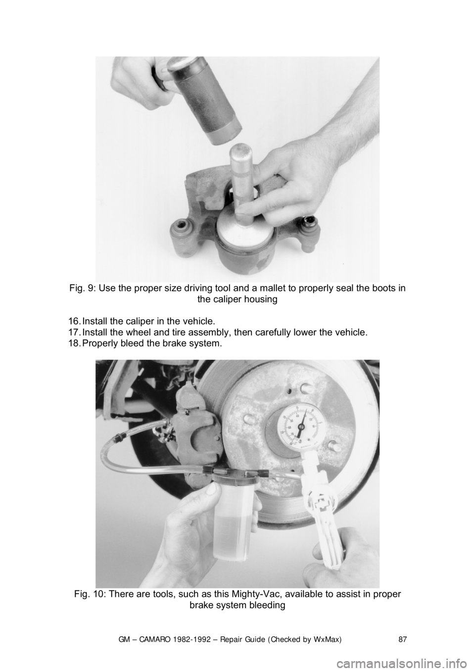
15. Use a suitable driving tool to seat the boots in the housing.
Page 87 of 875
GM – CAMARO 1982-1992 – Repair Guide (Checked by WxMax) 87
Fig. 9: Use the proper size driving tool and a mallet to properly seal the boots in
the caliper housing
16. Install the caliper in the vehicle.
17. Install the wheel and tire assembly , then carefully lower the vehicle.
18. Properly bleed t he brake system.
Fig. 10: There are tools, such as this Mighty-Vac, available to assist in proper
brake system bleeding
Page 102 of 875

GM – CAMARO 1982-1992 – Repair Guide (Checked by WxMax) 102
CAUTION
- Brake shoes may contain asbest os, which has been determined to
be a cancer causing agent. Never clean the brake surfaces with compressed
air! Avoid inhaling any dust from any brake surface! When cleaning brake
surfaces, use a commercially available brake cleaning fluid.
1. Raise and support the car. Remove t he wheel. Remove the brake shoes by
following the Brake Shoe R eplacement procedure.
2. Remove dirt from ar ound the wheel cylinder inle t and pilot. Disconnect the
inlet tube.
3. Using 2 awls,
1/8 in. (3mm) in diameter, or J29839, remove the wheel
cylinder retainer. Insert the awls in to the access slots between the wheel
cylinder pilot and retainer. Simultaneous ly, bend both tabs away from each
other. Remove the wheel cylinder.
To install:
4. Place wheel cylinder into position and place a block of wood between it and
the axle flange. Install a new retainer over the end of the wheel cylinder.
Using a 1
1/8 in. 12-point socket with an extensi on, drive the new retainer into
position.
5. Connect the inlet tube and torque 120-280 inch lbs. (13.6-20 Nm). Complete
installation by reversing the remova l procedure. Bleed the brakes.
OVERHAUL
Wheel cylinder overhaul kits may be available, but often at little or no savings
over a reconditioned wheel cylinder. It often makes sense with these
components to substitute a new or re conditioned part instead of attempting an
overhaul.
If no replacement is availabl e, or you would prefer to overhaul your wheel
cylinders, the following procedure may be used. When rebuilding and installing
wheel cylinders, avoid getting any cont aminants into the system. Always use
clean, new, high quality brake fluid. If di rty or improper fluid has been used, it
will be necessary to drain the entire syst em, flush the system with proper brake
fluid, replace all rubber components , then refill and bleed the system.
1. Remove the wheel cylinder from the vehicle and place on a clean
workbench.
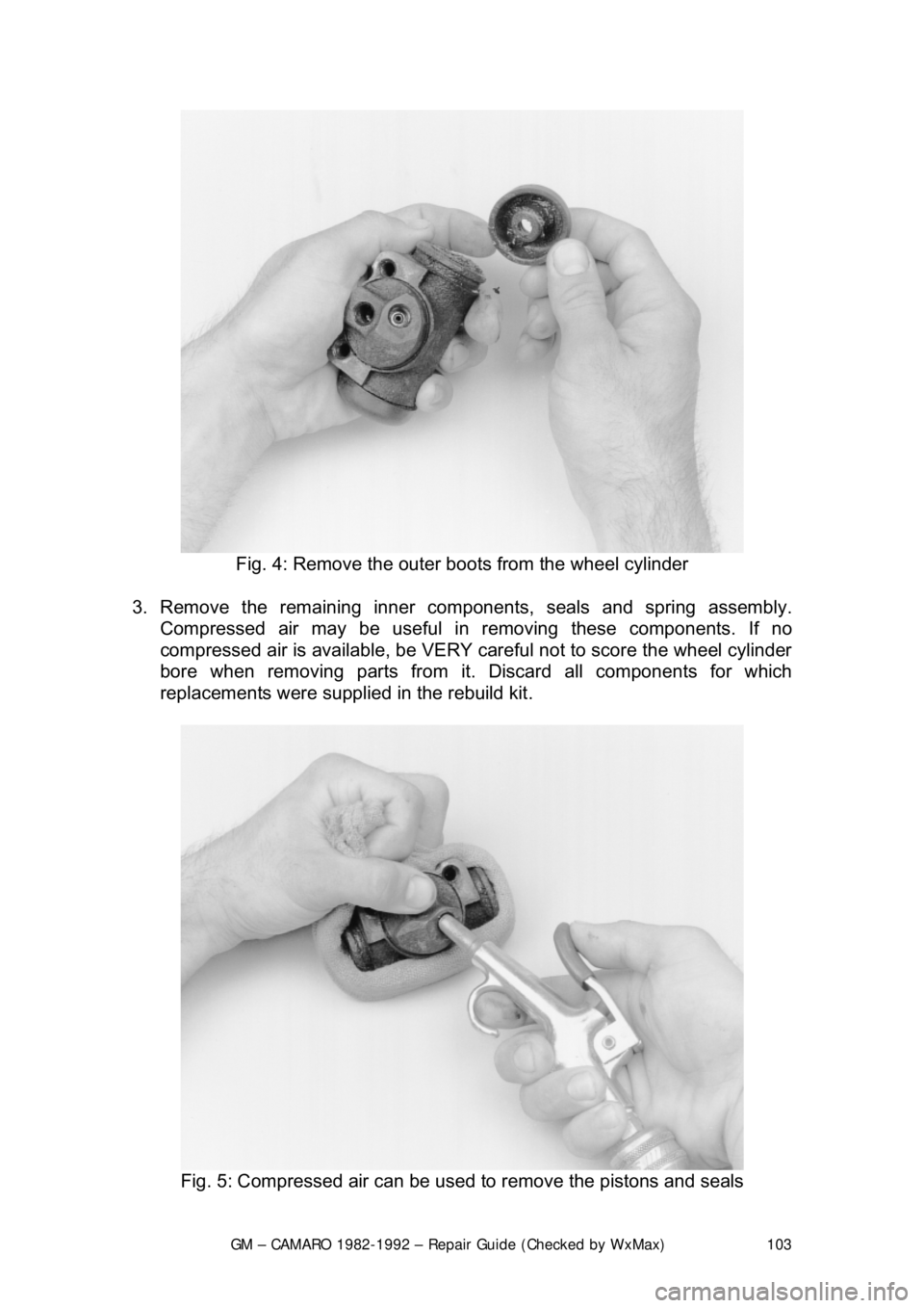
2. First remove and discard the old r ubber boots, then withdraw the pistons.
Piston cylinders are equipped with seals and a spring assembly, all located
behind the pistons in the cylinder bore.
Page 103 of 875
GM – CAMARO 1982-1992 – Repair Guide (Checked by WxMax) 103
Fig. 4: Remove the outer boots from the wheel cylinder
3. Remove the remaining inner com ponents, seals and spring assembly.
Compressed air may be useful in removing these components. If no
compressed air is available, be VERY careful not to score the wheel cylinder
bore when removing parts from i t. Discard all components for which
replacements were supplied in the rebuild kit.
Fig. 5: Compressed air can be used to remove the pistons and seals
Page 107 of 875
GM – CAMARO 1982-1992 – Repair Guide (Checked by WxMax) 107
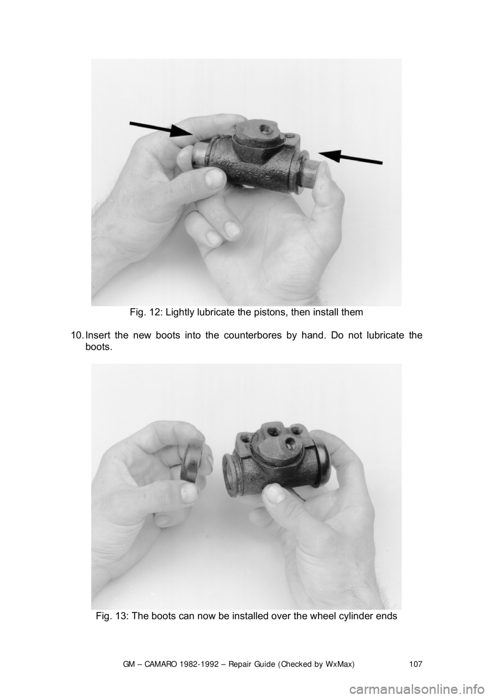
Fig. 12: Lightly lubricate t he pistons, then install them
10. Insert the new boots in to the counterbores by hand. Do not lubricate the
boots.
Fig. 13: The boots can now be installed over the wheel cylinder ends