check transmission fluid CHEVROLET CAMARO 1982 Repair Guide
[x] Cancel search | Manufacturer: CHEVROLET, Model Year: 1982, Model line: CAMARO, Model: CHEVROLET CAMARO 1982Pages: 875, PDF Size: 88.64 MB
Page 295 of 875

GM – CAMARO 1982-1992 – Repair Guide (Checked by WxMax) 295
of the spring bow outward, pushing the pre
ssure plate into closer contact with
the clutch disc. As the disc and plate mo ve closer together, friction between the
two increases and slippage is reduced until, when full spring pressure is applied
(by fully releasing the pedal) the speed of the disc and plate are the same. This
stops all slipping, creating a direct connection between the plate and disc which
results in the transfer of power from t he engine to the transmission. The clutch
disc is now rotating with the pressure plate at engine speed and, because it is
splined to the transmission shaft, the shaft now turns at the same engine speed.
The clutch is operating properly if: 1. It will stall the engine when released with the vehicle held stationary.
2. The shift lever can be moved freel y between 1st and reverse gears when
the vehicle is stationary and the clutch disengaged.
APPLICATION
All 1982-83 vehicles use a mechanical (non-hydraulic) clutch; 1984-92 models
use a hydraulic clutch. With the hydraulic clutch, no adjustment of the clutch
pedal or the linkage is required. On t he mechanical type, the only required
adjustment is to maintain the proper clutch pedal freeplay. The freeplay\
adjustment is very important, for it determines the engaging and disengaging
characteristics of the clutch assembly.
The clutch assembly consists of: a flywheel, a pressure plate, a throwout
bearing and fork, a clutch pedal, and an actuating lever (non-hydraulic) or a
master cylinder/slave cylinder (hydraulic).
The hydraulic system utilizes a remote re servoir which is mounted to the power
brake booster, a master cy linder mounted to the cowl p anel and a slave cylinder
that is mounted to the bell housing. Th e system is operated directly by the
clutch pedal. When adding fl uid to the reservoir, always use a type which meets
DOT 3 specifications.
CAUTION - The clutch driven disc contains asbestos, which has been
determined to be a cancer causing agen t. Never clean clutch surfaces with
compressed air! Avoid inhaling any dus t from any clutch surface! When
cleaning clutch surfaces, use a commercia lly available brake cleaning fluid.
FREE-PLAY ADJUSTMENT
MECHANICAL LINKAGE 1. Disconnect the return sp ring at the clutch fork.
2. Hold the pedal against the rubber bumper on the dash brace.
3. Push the clutch fork so that th e throwout bearing lightly contacts the
pressure plate fingers.
Page 304 of 875

GM – CAMARO 1982-1992 – Repair Guide (Checked by WxMax) 304
Never release a depressed clutch pedal
with the bleeder screw open or air will
be drawn into the system.
AUTOMATIC TRANSMISSION
UNDERSTANDING AUTOMATIC TRANSMISSIONS
The automatic transmission allows eng ine torque and power to be transmitted
to the rear wheels within a narrow range of engine operating speeds. It will
allow the engine to turn fast enough to produce plenty of power and torque at
very low speeds, while keeping it at a s ensible rpm at high vehicle speeds (and
it does this job without driv er assistance). The transmission uses a light fluid as
the medium for the transmission of power. This fluid also works in the operation
of various hydraulic control circui ts and as a lubricant. Because the
transmission fluid performs all of thes e functions, trouble within the unit can
easily travel from one part to another. For this reason, and because of the
complexity and unusual oper ating principles of the transmission, a very sound
understanding of the basic principles of operation will simplify troubleshooting.
TORQUE CONVERTER
The torque converter replaces the convent ional clutch. It has three functions:
1. It allows the engine to idle with t he vehicle at a standstill, even with the
transmission in gear.
2. It allows the transmission to shi ft from range-to-range smoothly, without
requiring that the driver close the throttle during the shift.
3. It multiplies engine torque to an incr easing extent as vehicle speed drops
and throttle opening is increased. This has the effect of making the
transmission more responsive and redu ces the amount of shifting
required.
The torque converter is a metal case which is shaped like a sphere that
has been flattened on opposite sides. It is bolted to the rear end of the
engine's crankshaft. Generally, the ent ire metal case rotates at engine
speed and serves as the engine's flywheel.
The case contains three sets of bl ades. One set is attached directly to
the case. This set forms the torus or pump. Another set is directly
connected to the output shaft, and forms the turbine. The third set is
mounted on a hub which, in turn, is mounted on a stationary shaft
through a one-way clutch. This third set is known as the stator.
A pump, which is driven by the conv erter hub at engine speed, keeps the
torque converter full of transmission fluid at all times. Fluid flows
continuously through the unit to provide cooling.
Under low speed acceleration, the tor que converter functions as follows:
Page 306 of 875
GM – CAMARO 1982-1992 – Repair Guide (Checked by WxMax) 306
As the speed of the turbine increases, th
e fluid spins faster and faster in the
direction of engine rotation. As a result, t he ability of the stator to redirect the
fluid flow is reduced. Under cruising conditions, the stator is eventually forced to
rotate on its one-way clutch in the dire ction of engine rotation. Under these
conditions, the torque converter begins to behave almost like a solid shaft, with
the torus and turbine speeds being almost equal.
PLANETARY GEARBOX
The ability of the torque converter to mult iply engine torque is limited. Also, the
unit tends to be more efficient when the turbine is rotating at relatively high
speeds. Therefore, a planetar y gearbox is used to carry the power output of the
turbine to the driveshaft.
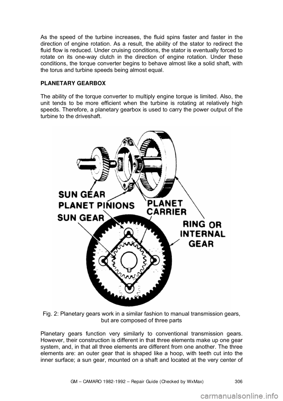
Fig. 2: Planetary gears work in a sim ilar fashion to manual transmission gears,
but are composed of three parts
Planetary gears function very similarly to conventional transmission gears.
However, their construction is different in that three elements make up one gear
system, and, in that all three elements ar e different from one another. The three
elements are: an outer gear that is shaped like a hoop, with teeth cut into the
inner surface; a sun gear, mounted on a sha ft and located at the very center of
Page 308 of 875
GM – CAMARO 1982-1992 – Repair Guide (Checked by WxMax) 308
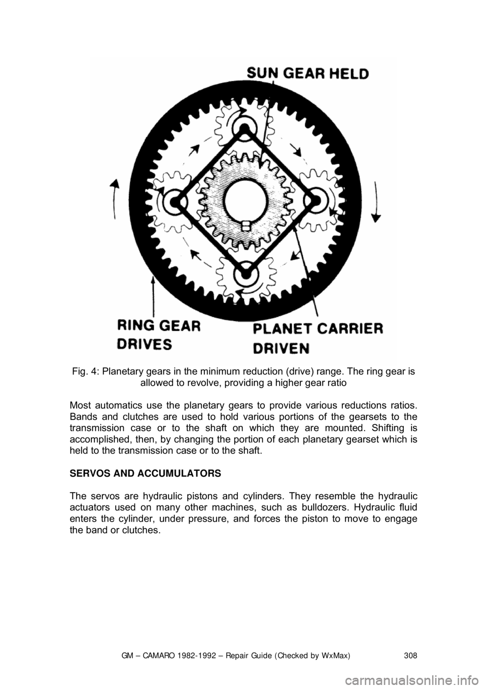
Fig. 4: Planetary gears in the minimum reduction (drive) range. The ring gear is
allowed to revolve, providing a higher gear ratio
Most automatics use the pl anetary gears to provide various reductions ratios.
Bands and clutches are used to hold va rious portions of the gearsets to the
transmission case or to the shaft on which they are mounted. Shifting is\
accomplished, then, by c hanging the portion of each planetary gearset which is
held to the transmission case or to the shaft.
SERVOS AND ACCUMULATORS
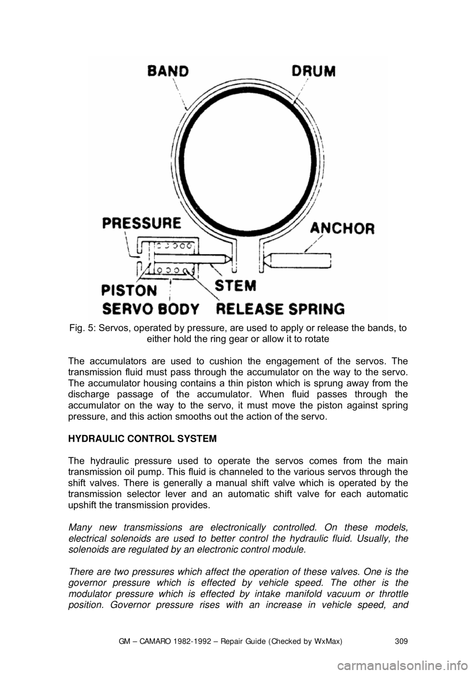
The servos are hydraulic pistons and cylinders. They resemble the hydrau\
lic
actuators used on many other machines, such as bulldozers. Hydraulic fluid
enters the cylinder, under pressure, and fo rces the piston to move to engage
the band or clutches.
Page 309 of 875
GM – CAMARO 1982-1992 – Repair Guide (Checked by WxMax) 309
Fig. 5: Servos, operated by pressure, ar e used to apply or release the bands, to
either hold the ring gear or allow it to rotate
The accumulators are used to cushi on the engagement of the servos. The
transmission fluid must pass through the ac cumulator on the way to the servo.
The accumulator housing contains a thin piston which is sprung away from the
discharge passage of the accumulato r. When fluid passes through the
accumulator on the way to the servo, it must move the piston against spring
pressure, and this action smooths out the action of the servo.
HYDRAULIC CONTROL SYSTEM
The hydraulic pressure used to operat e the servos comes from the main
transmission oil pump. This fluid is channel ed to the various servos through the
shift valves. There is generally a manual shift valve which is operated by the
transmission selector lever and an automat ic shift valve for each automatic
upshift the transmission provides.
Many new transmissions are electroni cally controlled. On these models,
electrical solenoids are used to better control the hydraulic fluid. Usually, the
solenoids are regulated by an electronic control module.
There are two pressures which affect t he operation of these valves. One is the
governor pressure which is effected by vehicle speed. The other is the
modulator pressure which is effected by intake manifold vacuum or throttle
position. Governor pressure rises wit h an increase in vehicle speed, and
Page 310 of 875

GM – CAMARO 1982-1992 – Repair Guide (Checked by WxMax) 310
modulator pressure rises as the thro
ttle is opened wider. By responding to these
two pressures, the shift valves caus e the upshift points to be delayed with
increased throttle opening to make the bes t use of the engine's power output.
Most transmissions also make use of an auxiliary circuit for downshifting. This
circuit may be actuated by the throttle linkage the vacuum line which actuates
the modulator, by a cable or by a solenoid. It applies pressure to a special
downshift surface on the shift valve or valves.
The transmission modulator also governs the line pressure, used to actuate the
servos. In this way, the clutches and bands will be actuated with a force
matching the torque output of the engine.
IDENTIFICATION
Two types of transmissions are used on th e vehicles; Turbo Hydra-Matic 200C
3-speed and Turbo Hydra-Matic 700-R4 4-speed. Beginning in 1991, the 700-
R4 was redesignated the 4L60.
FLUID PAN
REMOVAL, FLUID/FILTER CH ANGE, & INSTALLATION
Refer to General Information & Ma intenance for fluid pan procedures.
ADJUSTMENTS
BANDS
There are no band adjustments possible or required.
Page 317 of 875

GM – CAMARO 1982-1992 – Repair Guide (Checked by WxMax) 317
1. Place the shifter lever in the
P position. Remove the negative battery
cable.
2. Turn the key to RUN.
3. Remove the left side instrument panel sound insulator and kick panels.
4. Remove the floor console.
5. Remove the cable nut and clip. Remove the cable from the bracket, move the button to the UP position and unsnap the cable end from the
lever lock pin.
6. Lower the steering column. Remove the cable clips.
To install: 7. Place the shifter lever into the P position and the ignition key to the RUN
position.
8. After installing the cable ends, push the cable connector nose toward th\
e connector as far as possible and push down the lock button.
9. Complete the installation by reversing the removal procedure.
EXTENSION HOUSING SEAL (IN VEHICLE)
REMOVAL & INSTALLATION
This seal controls transmission oil leakage around the driveshaft. Continued
failure of this seal usually indicates a worn output shaft bushing. If so, there will
be signs of the same wear on the driveshaft where it contacts the seal and
bushing. The seal is available and is fairly simple to install, with the proper tool.
1. Raise and safely support rear of t he vehicle to minimize transmission oil
loss when the driveshaft is removed.
2. Unbolt the driveshaft fr om the differential and center support bearing, if
equipped. Wrap tape around the bearing cu ps to keep them in place on
the universal joint and slide the sh aft out of the transmission.
3. Use a small pry tool to carefully pr y out the old seal. Be careful not to
insert the tool too far into the hous ing or the bushing will be damaged.
4. Use an oil seal installation tool to evenly drive the new seal into the
housing. Make sure the tool only cont acts the outer metal portion of the
seal.
5. Install the driveshaft. Torque the uni versal bearing cup retainer bolts to
15 ft. lbs. (20 Nm). Recheck fluid level.
TRANSMISSION
REMOVAL & INSTALLATION 1. Disconnect the negative batte ry cable at the battery.
2. Remove the air cleaner assembly.
3. Disconnect the throttle valve (TV) control cable at the carburetor.
Page 320 of 875
GM – CAMARO 1982-1992 – Repair Guide (Checked by WxMax) 320
7. Unbolt the universal joint straps fr
om the pinion flange (use care to keep
the universal joint caps in place), lower and remove the driveshaft from
the vehicle. Place a transmission tailshaft plug or rag in place of the \
driveshaft to keep the transmission fluid from draining out.
8. Disconnect the catalytic converter support bracket at the transmission.
9. Disconnect the speedometer cable, electrical connectors and the shift
control cable from the transmission.
CAUTION - During the next step, rear spring force will cause the torque arm to
move toward the floor pan. When disconn ecting the arm from the transmission,
carefully place a piece of wood between the floor pan and the torque arm. This
will prevent possible personal injury and/or floor pan damage
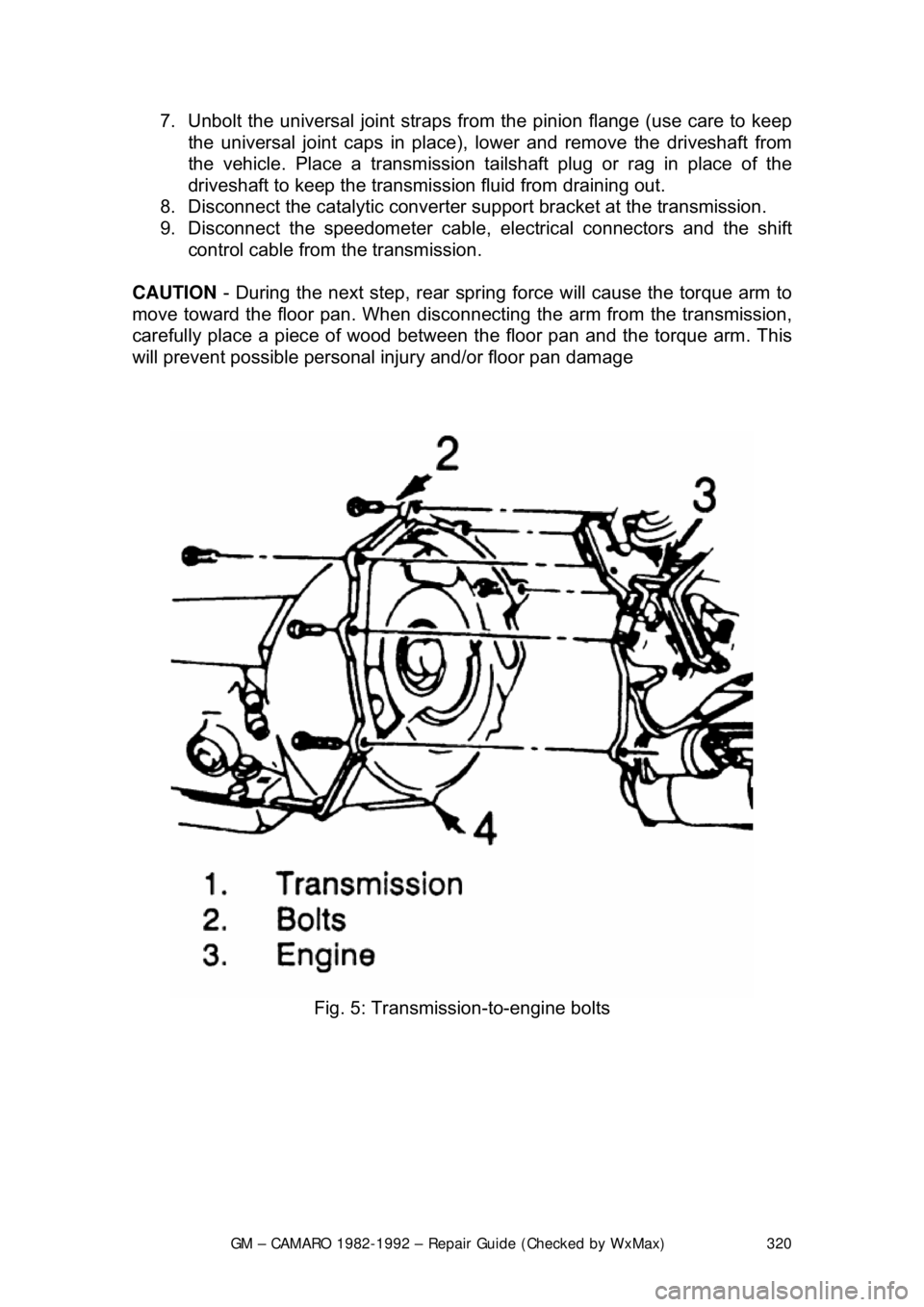
Fig. 5: Transmission-to-engine bolts
Page 364 of 875

GM – CAMARO 1982-1992 – Repair Guide (Checked by WxMax) 364
5. Drain the radiator and remove t
he radiator hoses. Disconnect the heater
hoses and the transmission cooler lines.
6. Remove the upper half of the radi ator shroud, if equipped with a manual
transmission. Remove the radiator and fan shroud assembly, if equipped
with an automatic transmission.
7. Disconnect the throttle linkage, includi ng the cruise control detent cable.
8. Remove the air conditioning compressor and lay aside.
Do not disconnect the air conditioning lines.
9. Disconnect the power steering pump and drain the fluid into a suitable
container. Remove the vacuum brake booster line.
10. Remove the distributor cap and spark plug wires.
11. Disconnect the engine electrical connection at the bulkhead connection
and disconnect any necessary vacuum hoses.
12. Working inside the vehicle, re move the right-hand hush panel and
disconnect the ECM harness at the EC M. Raise and safely support the
vehicle. Remove the right fenderwell splash shield and feed the harness
through the fenderwell.
13. Disconnect the exhaust pipes at the exhaust manifolds and remove
exhaust system from the vehicle.
14. Remove the flywheel cover and remo ve the converter bolts, if equipped
with automatic transmission.
15. Disconnect the transmission an d starter wire connections.
16. Remove the bellhousing and t he motor mount through-bolts.
17. Disconnect the clutch fork return spring, if equipped with a manual
transmission. Lower the vehicle.
18. Relieve the fuel system pressu re. Disconnect the fuel lines.
19. Support the transmission with a suit able jack. Attach an engine lifting
device.
20. Remove the engine assembly.
To install: 21. Position the engine assembly in the vehicle.
22. Attach the motor mount to engine br ackets and lower the engine in place.
Remove the engine lifting device and the transmission jack.
23. Raise and support the vehicle safely.
24. Install the motor mount through-bolts and tighten the nuts to specification. Install t he bellhousing bolts and tight en to 35 ft. lbs. (47
Nm).
25. On vehicles with automatic transmissi on, install the converter to flywheel
attaching bolts to 46 ft. lbs. (63 Nm).
26. Install the flywheel splash shield and tighten to 89 inch lbs. (10 Nm).
Install the clutch return spring, if equipped with manual transmission.
27. Connect the starter wires and the fuel lines.
28. Install the exhaust system.
29. Lower the vehicle.
30. Install the power steering pump and the air conditioning compressor.
Page 403 of 875
GM – CAMARO 1982-1992 – Repair Guide (Checked by WxMax) 403
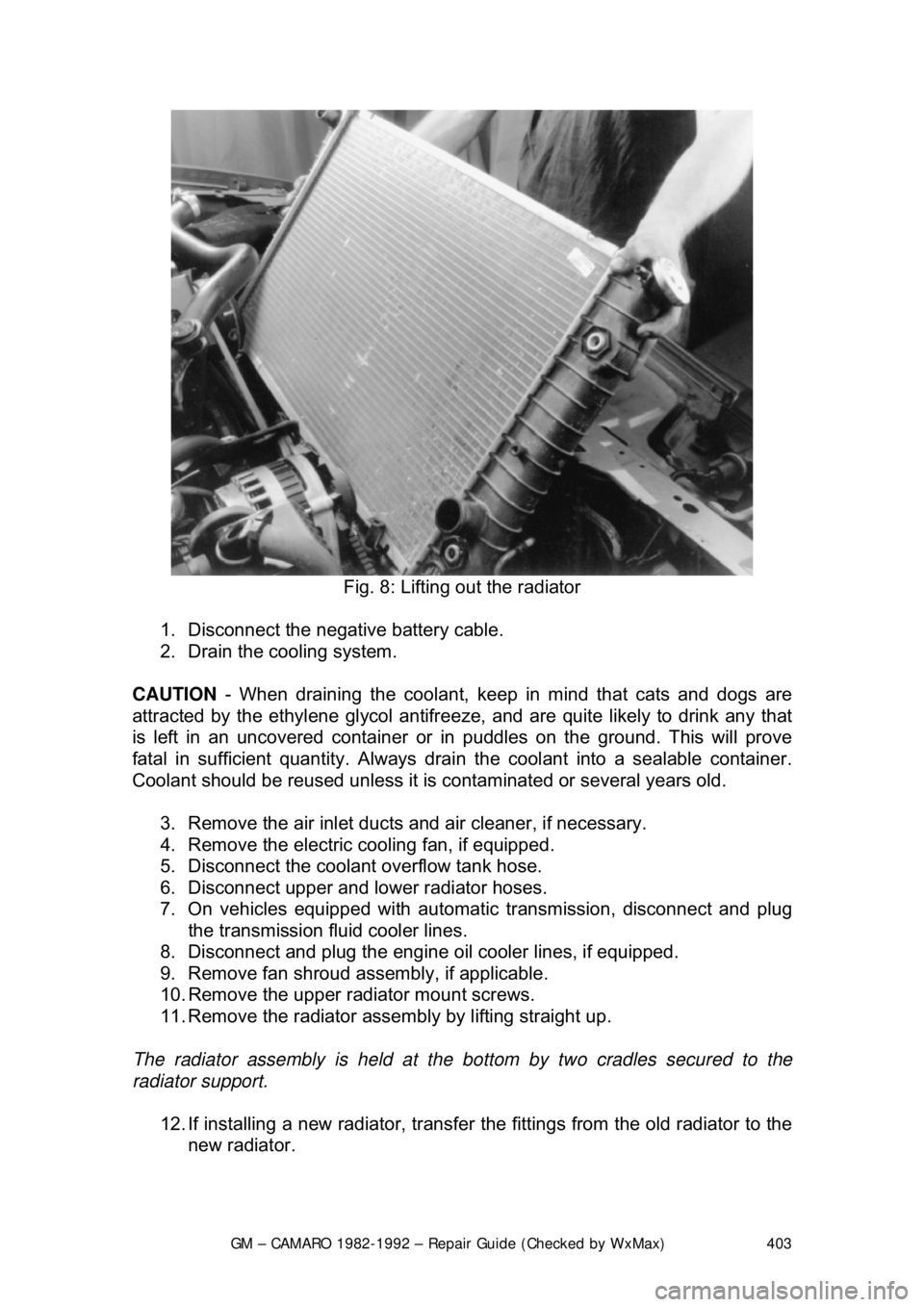
Fig. 8: Lifting out the radiator
1. Disconnect the negative battery cable.
2. Drain the cooling system.
CAUTION - When draining the coolant, keep in mind that cats and dogs are
attracted by the ethylene gl ycol antifreeze, and are quite likely to drink any that
is left in an uncovered container or in puddles on the ground. This will prove
fatal in sufficient quantity. Always drai n the coolant into a sealable container.
Coolant should be reused unless it is contaminated or several years old.
3. Remove the air inlet ducts and air cleaner, if necessary.
4. Remove the electric cooling fan, if equipped.
5. Disconnect the coolant overflow tank hose.
6. Disconnect upper and lower radiator hoses.
7. On vehicles equipped with automat ic transmission, disconnect and plug
the transmission fluid cooler lines.
8. Disconnect and plug the engine oil cooler lines, if equipped.
9. Remove fan shroud a ssembly, if applicable.
10. Remove the upper radiator mount screws.
11. Remove the radiator assembly by lifting straight up.
The radiator assembly is held at the bottom by tw o cradles secured to the
radiator support.
12. If installing a new radiat or, transfer the fittings from the old radiator to the
new radiator.