fuel tank removal CHEVROLET CAMARO 1982 Repair Guide
[x] Cancel search | Manufacturer: CHEVROLET, Model Year: 1982, Model line: CAMARO, Model: CHEVROLET CAMARO 1982Pages: 875, PDF Size: 88.64 MB
Page 217 of 875

GM – CAMARO 1982-1992 – Repair Guide (Checked by WxMax) 217
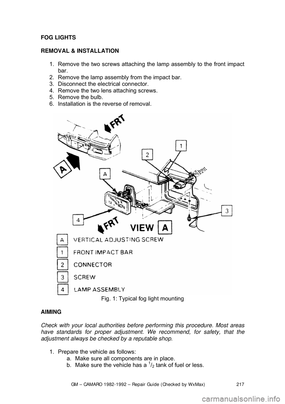
FOG LIGHTS
REMOVAL & INSTALLATION
1. Remove the two screws attaching the lamp assembly to the front impact
bar.
2. Remove the lamp assembly from the impact bar.
3. Disconnect the electrical connector.
4. Remove the two lens attaching screws.
5. Remove the bulb.
6. Installation is the reverse of removal.
Fig. 1: Typical fog light mounting
AIMING
Check with your local authorities before performing this procedure. Most areas
have standards for proper adjustment. We recommend, for safety, that the
adjustment always be checked by a reputable shop.
1. Prepare the vehicle as follows: a. Make sure all com ponents are in place.
b. Make sure the vehicle has a
1/2 tank of fuel or less.
Page 463 of 875

GM – CAMARO 1982-1992 – Repair Guide (Checked by WxMax) 463
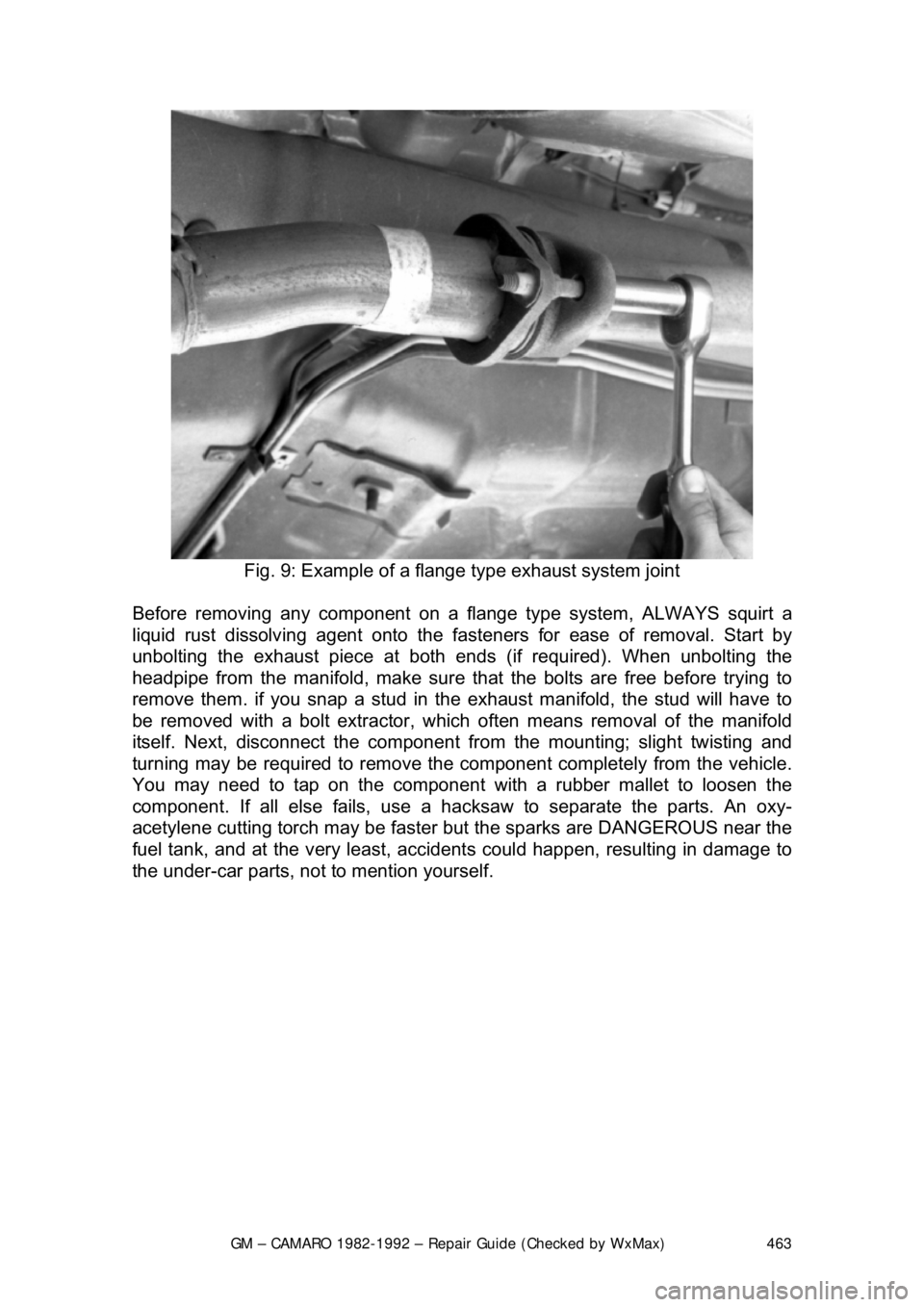
Fig. 9: Example of a fl ange type exhaust system joint
Before removing any component on a fl ange type system, ALWAYS squirt a
liquid rust dissolving agent onto the fast eners for ease of removal. Start by
unbolting the exhaust piece at both ends (if required). When unbolting the
headpipe from the manifold, make sure that the bolts are free before trying to
remove them. if you snap a stud in t he exhaust manifold, the stud will have to
be removed with a bolt extractor, which often means removal of the manifold
itself. Next, disconnect the component fr om the mounting; slight twisting and
turning may be required to remove the co mponent completely from the vehicle.
You may need to tap on the component wit h a rubber mallet to loosen the
component. If all else fails, use a hacksaw to separate the parts. An oxy-
acetylene cutting torch may be faster but the sparks are DANGEROUS near the
fuel tank, and at the very least, accident s could happen, resulting in damage to
the under-car parts, not to mention yourself.
Page 711 of 875

GM – CAMARO 1982-1992 – Repair Guide (Checked by WxMax) 711
THROTTLE BODY INJECTION SYSTEM
SYSTEM DESCRIPTION
The throttle body injection (TBI) system used on 2.5L (VIN 2) and 5.0L (VIN E)
engines is centrally located
on the intake manifold. Its function is to supply the
correct air/fuel mixture to the engine, as directed by the Engine Control Module
(ECM).
The TBI unit consists of two relatively simple casting assemblies: a throttle body
and a fuel metering assembly. Components include, a pressure regulator, idle
air control valve, fuel injector(s), thro ttle position sensor, fuel inlet and a fuel
return fitting.
The Throttle Body Injection identifi cation number is stamped on the lower
mounting flange located near the TPS. Th e number is in alphabetical code and
should be noted before servicing the unit.
An oxygen sensor in the exhaust syst em functions to provide feedback
information to the ECM as to oxygen content in the exhaust. The ECM then
uses this information to modify fuel de livery to achieve as near as possible an
ideal air/fuel ratio of 14.7 :1. This ratio permits the ca talytic converter to become
more effective in reducing emissions wh ile providing acceptable driveability.
Should you encounter any type of engine performance problem, have a
complete CCC system test performed by a qualified, professional technician. If
the fault lies in the injection system, you can use the following procedures to
remove the TBI unit and replace the defective component(s).
RELIEVING FUEL SYSTEM PRESSURE
1. Disconnect the negative battery cable to prevent fuel discharge if the key
is accidentally turned to the RUN position.
2. Loosen the fuel filler cap to relieve fuel tank pressure and do not tighten
until service has been completed.
3. Fuel system pressure is automatic ally relieved when the engine is turned
OFF. No further action is necessary.
When disconnecting fuel lines, there ma y still be a small amount of fuel
released. Cover the fuel line connection wi th a shop cloth to collect the fuel,
then place the cloth in an approved container.
ELECTRIC FUEL PUMP
REMOVAL & INSTALLATION
The fuel pump is part of t he fuel sender assembly located inside the fuel tank.
1. Release the fuel syst em pressure and disconnec t the negative battery
cable.
Page 736 of 875

GM – CAMARO 1982-1992 – Repair Guide (Checked by WxMax) 736
The mass air flow systems measure the
mass of air that is drawn into the
engine cylinders, rather than just the vo lume. The sensor contains a hot-wire
sensing unit, which is made up of an electronic balanced bridge network.
Whenever current is suppli ed to the sensor, the bridge is energized and the
sensing hot-wire is heated. As the air enter s the mass air flow sensor, it passes
over and cools the hot wire. When the hot wire is cooled, it's resistance changes
and additional current is needed to k eep the bridge network balanced. This
increase in current is sent to the computer as a voltage signal and is used to
calculate the mass of the incoming air. The ECM uses this information to\
determine the duration of fuel injection pulse, ignition timing and EGR operation.
The speed density systems calculate the volume of air moving through the
intake. The ECM establishes the speed fact or through a signal from the ignition
module. The Manifold or Intake Air Temperature (MAT/IAT) and the Engine
Coolant Temperature (ECT) sensors work together to assure that proper
temperature information gets to the ECM wh ile the Manifold Absolute Pressure
(MAP) sensor monitors the changes in m anifold pressure which results from
changes in engine loading. These three se nsors contribute to the density factor.
Together, these inputs (engine speed, coolant temperature sensor, etc ...) are
the major determinants of the air/fuel mixture delivered by the fuel injection
system.
The following engines and fuel managem ent systems are covered in this
section:
• 1985-1989 2.8L MPFI - Mass Air Flow
• 1990-1992 3.1L MPFI - Speed Density
• 1985-1989 5.0L and 5.7L TPI - Mass Air Flow
• 1990-1992 5.0L and 5.7L TPI - Speed Density
Relieving Fuel System Pressure
1. Disconnect the negative battery cable to prevent fuel discharge if the key
is accidentally turned to the RUN position.
2. Loosen the fuel filler cap to reliev e the tank pressure and do not tighten
until service has been completed.
3. Connect J-34730-1 fuel pressure gauge or equivalent, to the fuel
pressure test valve. Wrap a shop towel around the fitting while
connecting the gauge to prevent spillage.
4. Place the end of the bleed hose into a suitable container and open the
valve to relieve the fuel system pressure.
ELECTRIC FUEL PUMP
REMOVAL & INSTALLATION
The fuel pump is part of t he fuel sender assembly located inside the fuel tank.
Page 739 of 875

GM – CAMARO 1982-1992 – Repair Guide (Checked by WxMax) 739
3. Make sure the ignition switch has
been in the OFF position for at least 10
seconds and that all accessories are OFF.
4. Turn the ignition switch ON and the pump will run for about 2 seconds.
Note the system pressure with t he pump running, it should be between
40-47 psi.
The ignition switch may have to be cycled to the ON position more than once to
obtain maximum pressure. It is also norma l for the pressure to drop slightly
when the pump first stops, but it should then hold steady.
5. If the pressure is not as specified, verify that fuel pump operation is
heard in the tank.
6. If fuel pump operation is not heard, inspect the fuel pump relay and
wiring.
7. If fuel pump operation is heard, inspect the filter and lines for restriction.
8. Start the engine and make sure the pr essure decreases about 3-10 psi at
idle.
9. If fuel pressure does not decrease, inspect the fuel pressure regulator
and hose.
10. Disconnect the fuel pressure gauge.
THROTTLE BODY
REMOVAL & INSTALLATION 1. Disconnect the negative (-) battery c able and partially drain the radiator.
2. Remove the air inlet duct and unplug the IAC and TPS electrical connectors.
3. Label and disconnect the vacuum and coolant lines.
4. Disconnect the accelerator, thro ttle valve (transmission control) and
cruise control cables, as applicable.
5. Remove the throttle body attaching bolts, then separate the throttle body from the plenum.
6. Discard the gasket.
To install: 7. Install the throttle body to the plenum using a new gasket. Tighten the \
bolts to specification.
8. Engage the accelerator, throttle valve and cruise control cables, as
necessary. Make sure that the link ages do not hold the throttle open.
9. Connect the vacuum and coolant lines.
10. Install the air inlet duct and plug the IAC and TPS electrical connectors
into their sockets.
11. Connect the negative (-) battery cable and refill the radiator.
12. With the engine OFF, check to s ee that the accelerator pedal is free.
Depress the pedal to the floor and release.
Page 754 of 875

GM – CAMARO 1982-1992 – Repair Guide (Checked by WxMax) 754
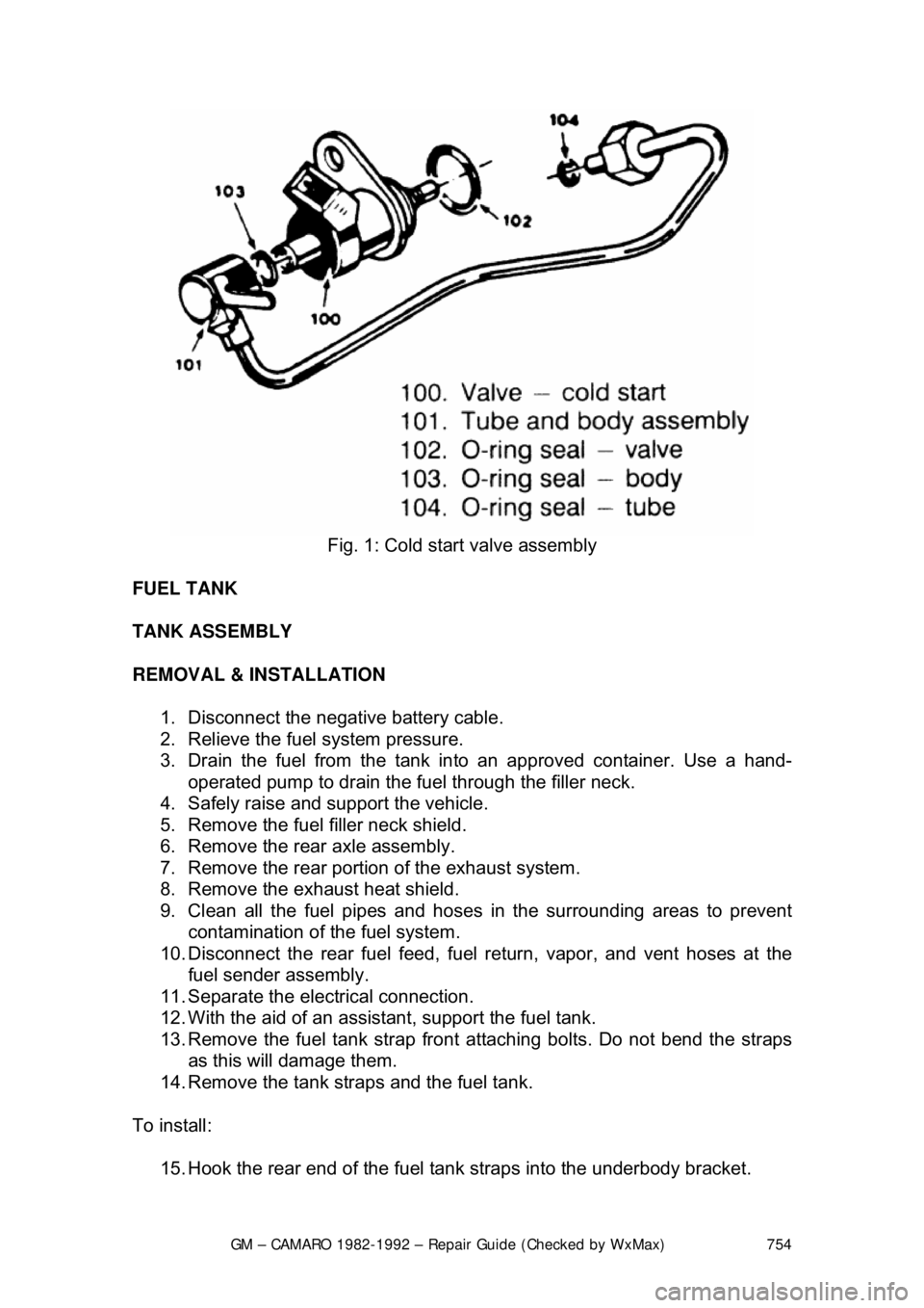
Fig. 1: Cold start valve assembly
FUEL TANK
TANK ASSEMBLY
REMOVAL & INSTALLATION 1. Disconnect the negative battery cable.
2. Relieve the fuel system pressure.
3. Drain the fuel from the tank in to an approved container. Use a hand-
operated pump to drain the fuel through the filler neck.
4. Safely raise and support the vehicle.
5. Remove the fuel filler neck shield.
6. Remove the rear axle assembly.
7. Remove the rear portion of the exhaust system.
8. Remove the exhaust heat shield.
9. Clean all the fuel pipes and hoses in the surrounding areas to prevent
contamination of the fuel system.
10. Disconnect the rear fuel feed, fuel return, vapor, and vent hoses at the
fuel sender assembly.
11. Separate the electrical connection.
12. With the aid of an assist ant, support the fuel tank.
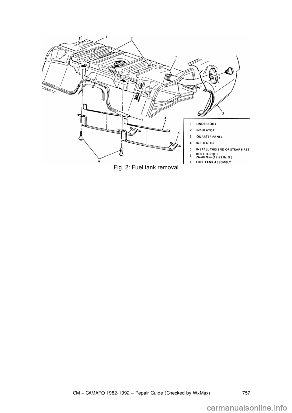
13. Remove the fuel tank strap front attaching bolts. Do not bend the straps
as this will damage them.
14. Remove the tank straps and the fuel tank.
To install: 15. Hook the rear end of the fuel t ank straps into the underbody bracket.
Page 755 of 875

GM – CAMARO 1982-1992 – Repair Guide (Checked by WxMax) 755
16. With the aid of an assistant, posit
ion and support the fuel tank with the
straps. Loosely install the front fuel tank attaching bolts.
17. Engage the electrical connection.
18. Connect the fuel hoses and li nes separated during removal.
19. Install the muffler heat sh ield and the exhaust system.
20. Install the rear axle and the fuel filler neck shield.
21. Lower the vehicle.
22. Add fuel and install the filler cap.
23. Connect the negative battery cable.
24. With the engine OFF, turn the igni tion switch to the ON position for 2
seconds, then turn it to the OFF positi on for 10 seconds. Again turn it to
the ON position and check for fuel leaks.
SENDING UNIT REPLACEMENT 1. Remove the fuel tank.
2. Clean the area surrounding t he sender assembly to prevent
contamination of the fuel system.
3. Using tool J-24187 or equivalent, re move the sending unit retaining cam.
Remove the fuel sender and O-rings fr om the tank. Discard the O-rings.
4. If necessary, separate the fuel pum p from the sending unit assembly.
To install: 5. If removed, install the fuel pump to the sending unit. If the strainer was
removed, it must be re placed with a new one.
6. Inspect and clean the O-ring mating surfaces.
7. Install a new O-ring in the groove around the tank opening. If applicable,
install a new O-ring on t he fuel sender feed tube.
8. Install the fuel sender assembly as follows: a. The fuel pump strainer must be in a horizontal position, and when
installed, must not block the travel of the float arm. Gently fold the
strainer over itself an d slowly position the sending assembly in the
tank so the strainer is not dam aged or trapped by the sump walls.
9. Install the retaining cam us ing tool J-24187 or equivalent.
10. Install the fuel tank assembly.
Page 757 of 875

GM – CAMARO 1982-1992 – Repair Guide (Checked by WxMax) 757
Fig. 2: Fuel tank removal