length CHEVROLET CAMARO 1982 Repair Guide
[x] Cancel search | Manufacturer: CHEVROLET, Model Year: 1982, Model line: CAMARO, Model: CHEVROLET CAMARO 1982Pages: 875, PDF Size: 88.64 MB
Page 23 of 875

GM – CAMARO 1982-1992 – Repair Guide (Checked by WxMax) 23
4. Remove the No. 1 bow garni
sh molding and retainer.
5. Remove the top from the No. 1 bow by applying heat with a heat gun to the
approximately 1 in. (25mm) fr om the adhesive backed bow.
6. Remove the cable screws.
7. Remove the headliner from the No. 2 and 3 bows.
It is not necessary to remove the headliner from the No. 1 bow with the top
folded enough to allow access to the retainer screws.
8. Remove the screws from the under side of the Nos. 2 and 3 top cover
retainers.
9. Remove the No. 2 and 3 bow top cover from the pockets in the top cover.
10. Separate the outer quarter flaps fr om the main pillar post, once again using
the heat gun as necessary to loosen the adhesive.
11. Remove the side retention cables.
12. Remove screws.
13. Remove the elastic stays, folding the top rearward.
14. Remove the No. 5 bow seal.
15. Remove the black covered rive ts from the No. 5 bow using an
1/8 in. (3mm)
drill bit.
16. Remove the top cover from No. 5 bow, using heat as required to loosen th\
e adhesive.
17. Remove the convertible t op cover from the vehicle.
To install:
Use 3M® adhesive No. 8046 or equivalent on cover attaching surfaces where
noted.
18. Install the cover on the v ehicle. Slide the retention cables through the listing
pockets and check cable ends for proper locations.
19. Square the top to the frame; check fo r evenness of quarter flap positions to
the main pillar rail. Fold the t op cover to the windshield header.
20. Apply adhesive to the No . 5 bow and top, raise the No. 5 bow to the full
vertical position.
Glue
1/2 of the top cover to the No. 5 bow first, then lower the bow and check for
evenness. The length of the material ov erhanging should be uniform. Repeat
the procedure, if necessary. Trim the exce ss fabric from the No. 5 bow evenly at
the seal channel to allow atta chment of the seal later.
21. Install new
1/8 in. (3mm) by 3/16 in. (5mm) black aluminum rivets as shown in
illustration.
22. Lower and latch the tonneau cover and No. 5 bow. Raise the No. 1 bow off
the header and install the cable screws.
23. Install the No. 5 bow seal.
24. Connect the elastic stays inside of No . 5 bow seal-to-link arms. Install the
screws.
25. Lower the No. 5 bow. Fold the inner quarter flaps inside of main pillar rails.
Fold the outer quarter flaps around the outs ide of the main pillar rails to the
Page 74 of 875
GM – CAMARO 1982-1992 – Repair Guide (Checked by WxMax) 74
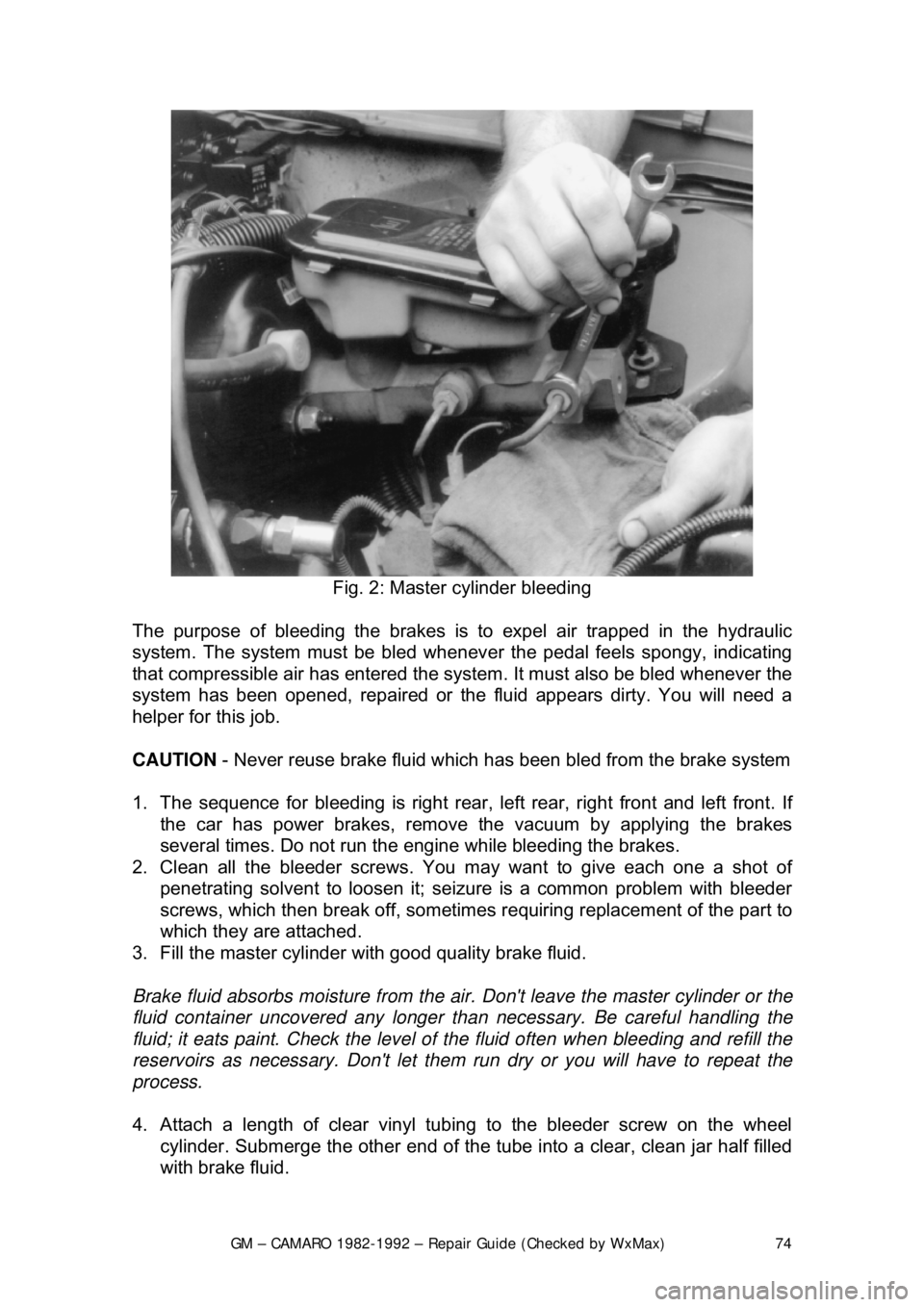
Fig. 2: Master cylinder bleeding
The purpose of bleeding the brakes is to expel air trapped in the hydraulic
system. The system must be bled whenever the pedal feels spongy, indicating
that compressible air has ent ered the system. It must also be bled whenever the
system has been opened, repaired or the fluid appears dirty. You will need a
helper for this job.
CAUTION - Never reuse brake fluid which has been bled from the brake system
1. The sequence for bleeding is right rear , left rear, right front and left front. If
the car has power brakes, remove the vacuum by applying the brakes
several times. Do not run the engine while bleeding the brakes.
2. Clean all the bleeder screws. You ma y want to give each one a shot of
penetrating solvent to loosen it; seiz ure is a common problem with bleeder
screws, which then break off, sometimes requiring replacement of the part to
which they are attached.
3. Fill the master cylinder with good quality brake fluid.
Brake fluid absorbs moisture from the air. Don't leave the master cylinder or the
fluid container uncovered any longer t han necessary. Be careful handling the
fluid; it eats paint. Check the level of the fluid often when bleeding and refill the
reservoirs as necessary. Don't let them run dry or you will have to repeat the
process.
4. Attach a length of clear vinyl t ubing to the bleeder screw on the wheel
cylinder. Submerge the other end of the tube into a clear, clean jar half filled
with brake fluid.
Page 80 of 875

GM – CAMARO 1982-1992 – Repair Guide (Checked by WxMax) 80
4. Remove the mounting bo
lts, if equipped with single piston caliper or the
circlip and pin, if equipped with dual piston ca liper. Inspect the bolts for
corrosion and replace as necessary.
5. Remove the caliper fr om the steering knuckle an d suspend it from the body
of the car with a length of wire. Do not allow the caliper to hang by its hose.
6. Remove the pad retaining springs and remove the pads from the caliper.
7. Remove the plastic sleeves and the rubber bushings from the mounting bolt
holes.
8. Obtain a pad replacem ent kit. Lubricate and install the new sleeves and
bushings with a light coat of silicone grease.
9. Install the retainer spring on the i nboard pad, if equipped with single piston
caliper.
A new spring should be included in the pad replacement kit.
10. Install the new inboard pad into the caliper with the wear sensor at the
leading end of the shoe duri ng forward wheel rotation.
11. Install the outboard pad into the caliper.
12. Use a large pair of slip joint plie rs to bend the outer pad ears down over the
caliper, if equipped with t he single piston caliper.
13. Install the calip er onto the steering knuckle. Tighten the mounting bolts to
21-35 ft. lbs. (28-47 Nm), if equipped. In stall the wheel and lower the car. Fill
the master cylinder to its proper le vel with a good quality brake fluid.
14. Pump the brake pedal slowly a nd firmly 3 times with the engine running
before attempting to move the vehicle; bleed the brakes as required.
BRAKE CALIPER
CAUTION - Some brake pads contain asbest os, which has been determined to
be a cancer causing agent. Never clean the brake surfaces with compressed
air! Avoid inhaling any dust from any brake surface! When cleaning brake
surfaces, use a commercially available brake cleaning fluid.
REMOVAL & INSTALATION
Page 128 of 875

GM – CAMARO 1982-1992 – Repair Guide (Checked by WxMax) 128
•
Size - the larger the wire size being used, the less resistance the wire will
have. This is why components which use large amounts of electricity
usually have large wires suppl ying current to them.
• Length - for a given thickness of wire, the longer the wire, the greater the
resistance. The shorter the wire, the less the resistance. When
determining the proper wire for a circ uit, both size and length must be
considered to design a circuit that can handle the current needs of the
component.
• Temperature - with many materials, the higher the temperature, the
greater the resistance (positive temper ature coefficient). Some materials
exhibit the opposite trait of lower re sistance with higher temperatures
(negative temperature coefficient). Thes e principles are used in many of
the sensors on the engine.
OHM'S LAW
There is a direct relationship between current, voltage and resistance. The
relationship between current, voltage and resistance can be summed up by a
statement known as Ohm's law.
Voltage (E) is equal to amper age (I) times resistance (R): E=I x ROther forms of
the formula are R=E/I and I=E/R
In each of these formulas, E is the voltage in volts, I is the current in amps and
R is the resistance in ohms. The basic point to remember is that as the
resistance of a circuit goes up, the amount of current that flows in the circuit will
go down, if voltage remains the same.
The amount of work that the electricity can perform is expressed as power. The
unit of power is the watt (w). The re lationship between power, voltage and
current is expressed as:
Power (w) is equal to amperage (I) times voltage (E): W=I x EThis is only true
for direct current (DC) circuits; The alte rnating current formula is a tad different,
but since the electrical circuits in mo st vehicles are DC type, we need not get
into AC circuit theory.
ELECTRICAL COMPONENTS
POWER SOURCE
Power is supplied to the vehicle by tw o devices: The battery and the alternator.
The battery supplies electrical power dur ing starting or during periods when the
current demand of the vehicle's electrical system exceeds the output capacity of
the alternator. The alternator supplies electrical current when the engine is
running. Just not does the al ternator supply the current needs of the vehicle, but
it recharges the battery.
Page 131 of 875
GM – CAMARO 1982-1992 – Repair Guide (Checked by WxMax) 131
•
Circuit Breaker - a circuit breaker is basically a self-repairing fuse. It will
open the circuit in the same fashio n as a fuse, but when the surge
subsides, the circuit breaker can be reset and does not need
replacement.
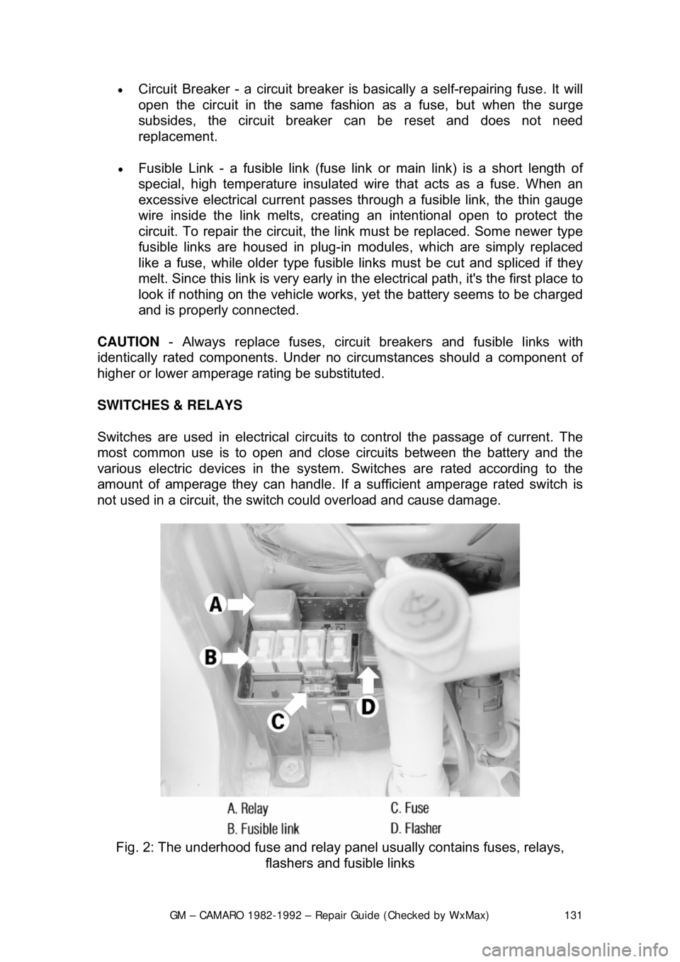
• Fusible Link - a fusible link (fuse link or main link) is a short length of
special, high temperatur e insulated wire that acts as a fuse. When an
excessive electrical current passes th rough a fusible link, the thin gauge
wire inside the link melt s, creating an intentional open to protect the
circuit. To repair the circuit, the link must be replaced. Some newer type
fusible links are housed in plug-in modules, which are simply replaced
like a fuse, while older type fusible lin ks must be cut and spliced if they
melt. Since this link is very early in the electrical path, it's the first place to
look if nothing on the vehicle works, yet the battery seems to be charged
and is properly connected.
CAUTION - Always replace fuses, circ uit breakers and fusible links with
identically rated component s. Under no circumstances should a component of
higher or lower amperage rating be substituted.
SWITCHES & RELAYS
Switches are used in electrical circuits to control the passage of current. The
most common use is to open and close circuits between the battery and the
various electric devices in the system. Switches are rated according to the
amount of amperage they c an handle. If a sufficient amperage rated switch is
not used in a circuit, the switch could overload and cause damage.
Fig. 2: The underhood fuse and relay panel usually contains fuses, relays,
flashers and fusible links
Page 135 of 875
GM – CAMARO 1982-1992 – Repair Guide (Checked by WxMax) 135
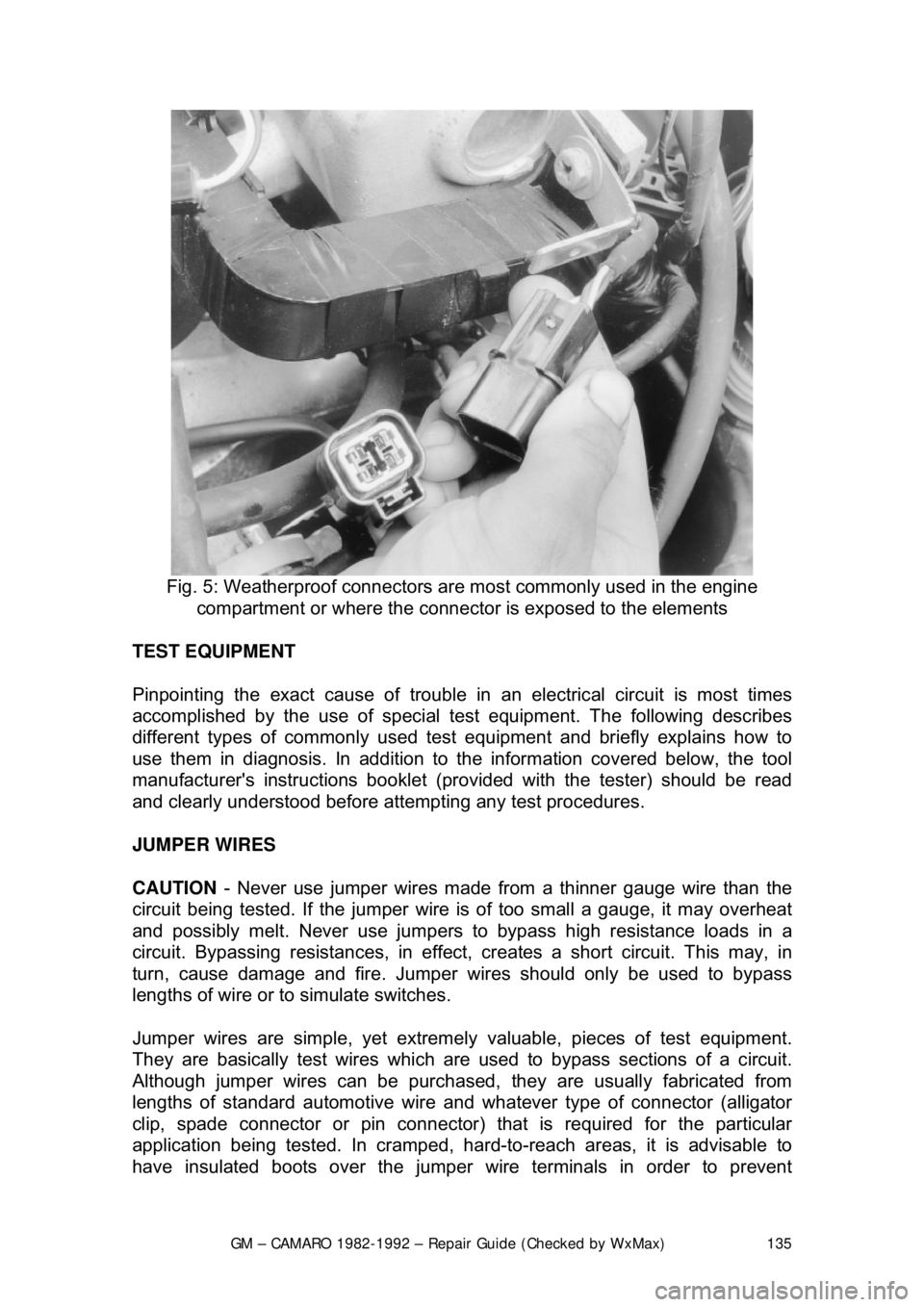
Fig. 5: Weatherproof connectors ar e most commonly used in the engine
compartment or where the connecto r is exposed to the elements
TEST EQUIPMENT
Pinpointing the exact cause of trouble in an electrical circuit is most times
accomplished by the use of special te st equipment. The following describes
different types of commonly used test eq uipment and briefly explains how to
use them in diagnosis. In addition to t he information covered below, the tool
manufacturer's instructions booklet (pro vided with the tester) should be read
and clearly understood before atte mpting any test procedures.
JUMPER WIRES
CAUTION - Never use jumper wires made from a thinner gauge wire than the
circuit being tested. If the jumper wire is of too small a gauge, it may overheat
and possibly melt. Never use jumpers to bypass high resistance loads in a
circuit. Bypassing resistances, in effect, cr eates a short circuit. This may, in
turn, cause damage and fire. Jumper wi res should only be used to bypass
lengths of wire or to simulate switches.
Jumper wires are simple, yet extremel y valuable, pieces of test equipment.
They are basically test wir es which are used to bypass sections of a circuit.
Although jumper wires can be purchased, they are usually fabricated from
lengths of standard automot ive wire and whatever type of connector (alligator
clip, spade connector or pin connector) that is required for the particular
application being tested. In cramped, hard- to-reach areas, it is advisable to
have insulated boots over the jumper wire terminals in order to prevent
Page 207 of 875
GM – CAMARO 1982-1992 – Repair Guide (Checked by WxMax) 207
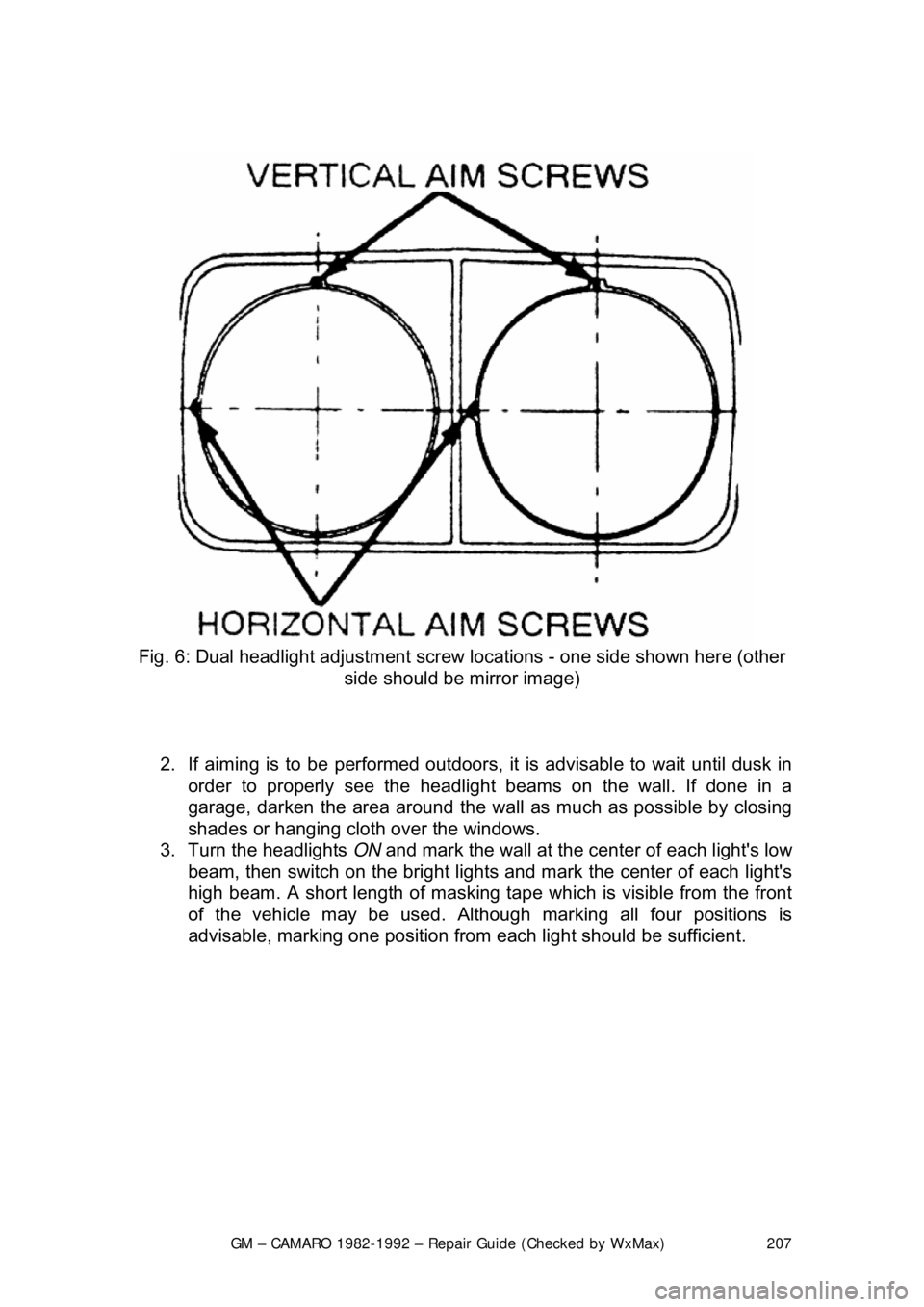
Fig. 6: Dual headlight adjustment screw locations - one side shown here (other
side should be mirror image)
2. If aiming is to be performed outdoors, it is advisable to wait until dusk in
order to properly see t he headlight beams on the wall. If done in a
garage, darken the area around the wall as much as possible by closing
shades or hanging cloth over the windows.
3. Turn the headlights ON and mark the wall at the center of each light's low
beam, then switch on the bright lights and mark the center of each light's
high beam. A short length of masking tape which is visible from the front
of the vehicle may be used. Althoug h marking all four positions is
advisable, marking one position from each light should be sufficient.
Page 296 of 875
GM – CAMARO 1982-1992 – Repair Guide (Checked by WxMax) 296
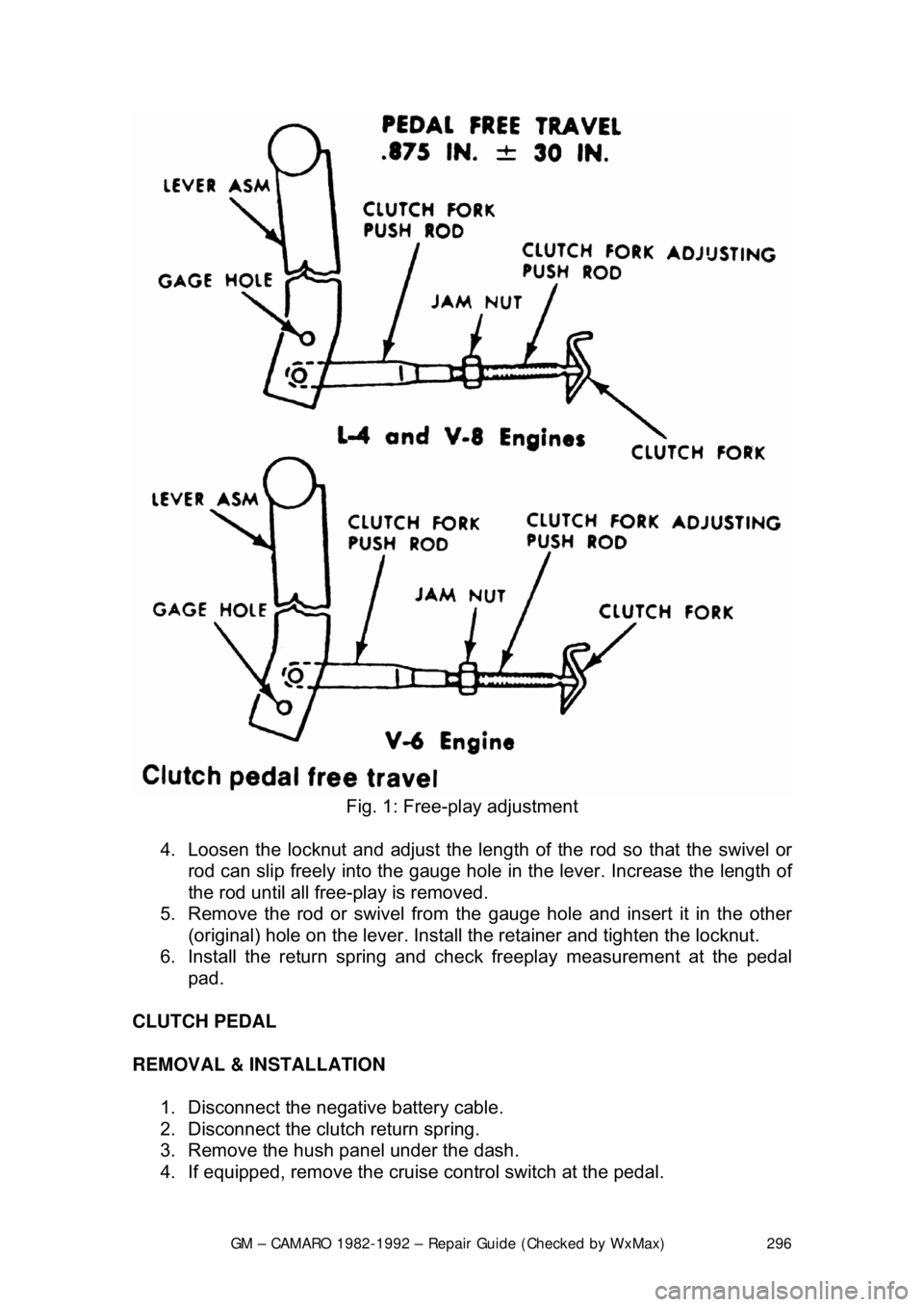
Fig. 1: Free-play adjustment
4. Loosen the locknut and adjust the length of the rod so that the swivel or
rod can slip freely into the gauge hole in the lever. Increase the length of
the rod until all free-play is removed.
5. Remove the rod or swivel from the gauge hole and insert it in the other
(original) hole on the lever. Install the retainer and tighten the loc\
knut.
6. Install the return spring and che ck freeplay measurement at the pedal
pad.
CLUTCH PEDAL
REMOVAL & INSTALLATION 1. Disconnect the negative battery cable.
2. Disconnect the clutch return spring.
3. Remove the hush panel under the dash.
4. If equipped, remove the cruise control switch at the pedal.
Page 456 of 875

GM – CAMARO 1982-1992 – Repair Guide (Checked by WxMax) 456
2. Drain the engine oil and remove the oil pan.
3. Remove the rear main bearing cap.
4. Insert packing tool J-29114-2 or equi
valent, against 1 end of the seal in
the cylinder block. Drive the old seal gently into the groove until it is
packed tight. This will vary from
1/4 in. (6mm) to 3/4 in. (19mm) depending
on the amount of pack required.
5. Repeat the procedure on t he other end of the seal.
6. Measure the amount the seal wa s driven up on one side and add
1/16 in.
(1.6mm). Using a suitable cutting tool, cut that length from the old seal
removed from the rear main beari ng cap. Repeat the procedure for the
other side. Use the rear main bear ing cap as a holding fixture when
cutting the seal.
7. Install guide tool J-29114-1 or equi valent, onto the cylinder block.
8. Using the packing tool, work the shor t pieces cut in Step 6 into the guide
tool and then pack into the cylinder block. The guide tool and packing
tool are machined to provide a built in stop. Use this procedure for both
sides. It may help to use oil on the short pieces of the rope seal when \
packing them into the cylinder block.
9. Remove the guide tool.
10. Apply Loctite® 414 or equivalent, to the seal groove in the rear main
bearing cap. Within 1 minute, insert a new seal into the groove and push
into place with tool J-29590 until the seal is flush with the block. Cut the
excess seal material with a sharp cu tting tool at the bearing cap parting
line.
11. Apply a thin film of chassis grease to the rope se al. Apply a thin film of
RTV sealant on the bearing cap mati ng surface around the seal groove.
Use the sealer sparingly.
12. Plastigage® the rear main bea ring cap as outlined in MEASURING
REAR MAIN CLEARANCE in this section and check with specification. If
out of specification, check for fr ying of the rope seal which may be
causing the cap to not seat properly.
13. Install all remaining com ponents and inspect for leaks.
FLYWHEEL AND RING GEAR
REMOVAL & INSTALLATION
The ring gear is an integral part of the flywheel and is not replaceable.
1. Remove the transmission.
2. Remove the six bolts attaching t he flywheel to the crankshaft flange.
Remove the flywheel.
3. Inspect the flywheel for cracks, and inspect the ring gear for burrs or
worn teeth. Replace the flywheel if any damage is apparent. Remove
burrs with a mill file.
4. Install the flywheel. Th e flywheel will only attach to the crankshaft in one
position, as the bolt holes are unevenly spaced. Install the bolts and
torque to specification. Tighten bolts in crisscross pattern.
Page 482 of 875
GM – CAMARO 1982-1992 – Repair Guide (Checked by WxMax) 482
If you do not have access to the proper
tools, you may want to bring the
components to a shop that does.
VALVES
The first thing to inspect are the valve heads. Look closely at the head, margin
and face for any cracks, excessive wear or burning. The margin is the best
place to look for burning. It should have a squared edge with an even width all
around the diameter. When a valve burns, the margin will look melted and the
edges rounded. Also inspect the valve head for any signs of tulipping. This will
show as a lifting of the edges or dishi ng in the center of the head and will
usually not occur to all of the valves. All of the heads should look the same, any
that seem dished more t han others are probably bad. Next, inspect the valve
lock grooves and valve tips. Check fo r any burrs around the lock grooves,
especially if you had to file them to remove the valve. Valve tips should appear
flat, although slight rounding with high mile age engines is normal. Slightly worn
valve tips will need to be machined flat. Last, measure the valve stem diameter
with the micrometer. Measure the area that rides within the guide, especially
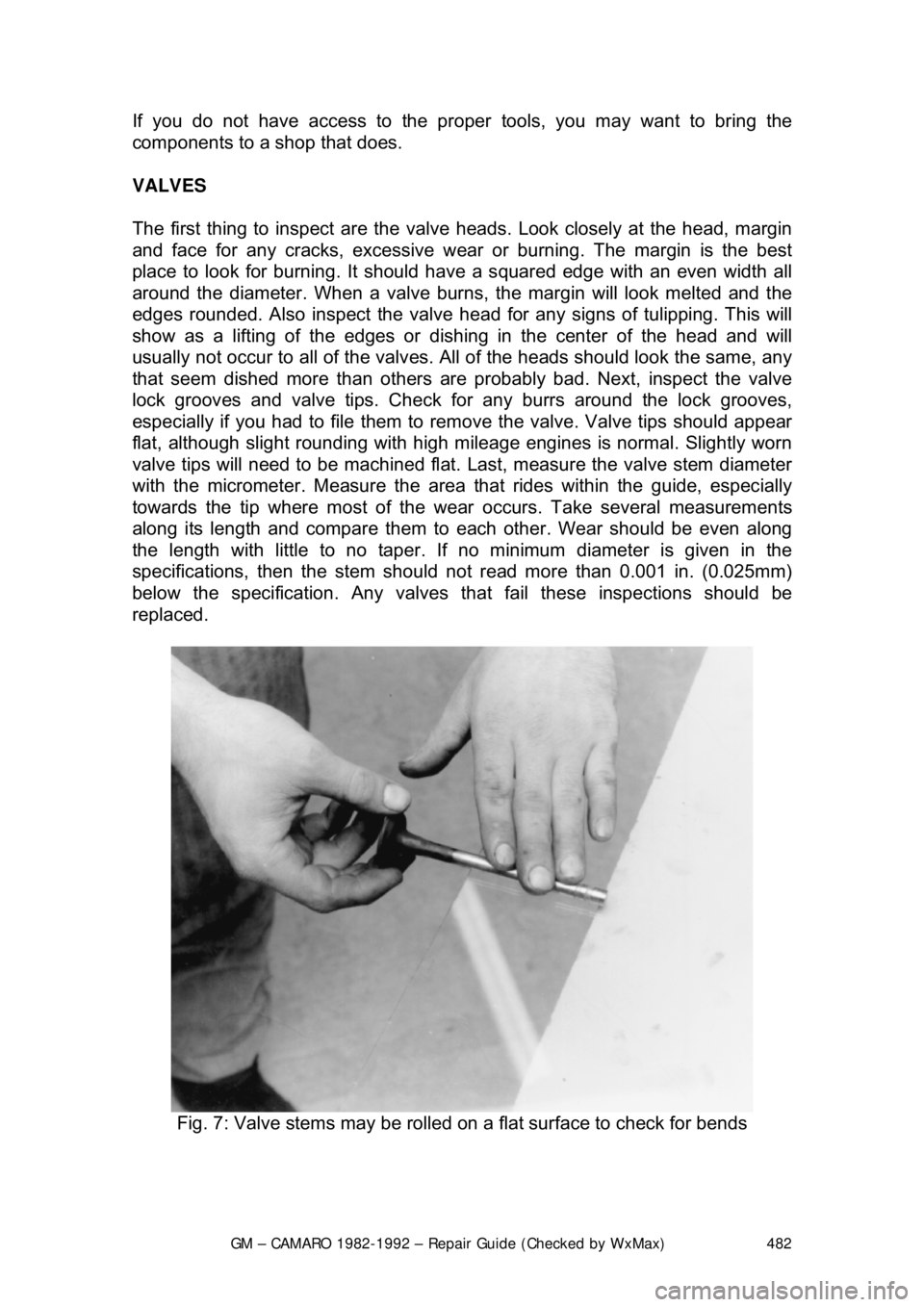
towards the tip where most of the wear occurs. Take several measurements
along its length and compare them to each other. Wear should be even along
the length with little to no taper. If no minimum diameter is given in the
specifications, then the stem should not read more than 0.001 in. (0.025mm)
below the specification. Any valves that fail these inspections should be
replaced.
Fig. 7: Valve stems may be rolled on a flat surface to check for bends