lights CHEVROLET CAMARO 1982 Repair Guide
[x] Cancel search | Manufacturer: CHEVROLET, Model Year: 1982, Model line: CAMARO, Model: CHEVROLET CAMARO 1982Pages: 875, PDF Size: 88.64 MB
Page 49 of 875

GM – CAMARO 1982-1992 – Repair Guide (Checked by WxMax) 49
Upon release of the brake pedal, a spri
ng located inside the master cylinder
immediately returns the master cylinder pistons to the normal position. The
pistons contain check valv es and the master cylinder has compensating ports
drilled in it. These are uncovered as the pistons reach their normal position. The
piston check valves allow fluid to flow to ward the wheel cylinders or calipers as
the pistons withdraw. Then, as the return springs force the brake pads or shoes
into the released position, the excess fluid reservoir through the compensating
ports. It is during the time the pedal is in the released position that any fluid that
has leaked out of the syst em will be replaced through the compensating ports.
Dual circuit master cylinders employ tw o pistons, located one behind the other,
in the same cylinder. The primary pist on is actuated directly by mechanical
linkage from the brake peda l through the power booster. The secondary piston
is actuated by fluid tra pped between the two pistons. If a leak develops in front
of the secondary piston, it moves forward until it bottoms against the front of the
master cylinder, and the fluid trapped betw een the pistons will operate the rear
brakes. If the rear brakes develop a l eak, the primary piston will move forward
until direct contact with the secondary pi ston takes place, and it will force the
secondary piston to actuate the front brakes. In either case, the brake pedal
moves farther when the brakes are applied, and less braking power is available.
All dual circuit systems use a switch to wa rn the driver when only half of the
brake system is operational. This switch is usually located in a valve body which
is mounted on the firewall or the frame below the master cylinder. A hydraulic
piston receives pressure from both circui ts, each circuit's pressure being applied
to one end of the piston. When the pressures are in balance, the piston remains
stationary. When one circuit has a leak, however, the greater pressure in that
circuit during application of the brakes will push the piston to one side, closing
the switch and activating the brake warning light.
In disc brake systems, this valve body also contains a metering valve and, in
some cases, a proportioning valve. The metering valve keeps pressure fro\
m
traveling to the disc brakes on the front wheels until the brake shoes on the rear
wheels have contacted the drums, ensuri ng that the front brakes will never be
used alone. The proportioning va lve controls the pressure to the rear brakes to
lessen the chance of rear wheel lo ck-up during very hard braking.
Warning lights may be tested by depressi ng the brake pedal and holding it while
opening one of the wheel cyli nder bleeder screws. If this does not cause the
light to go on, substitute a new lamp , make continuity checks, and, finally,
replace the switch as necessary.
The hydraulic system may be checked for leaks by applying pressure to the
pedal gradually and steadily. If the pedal sinks very slowly to the floor, the
system has a leak. This is not to be conf used with a springy or spongy feel due
to the compression of air within the lin es. If the system leaks, there will be a
gradual change in the position of the pedal with a constant pressure.
Check for leaks along all lines and at wheel cylinders. If no external leaks are
apparent, the problem is inside the master cylinder.
Page 66 of 875

GM – CAMARO 1982-1992 – Repair Guide (Checked by WxMax) 66
4. Remove nuts and lockwashers that se
cure booster to firewall and remove
booster from engine compartment.
5. Install by reversing removal procedure. Make sure to check operation of stop
lights. Allow engine vacuum to build before applying brakes.
COMBINATION VALVE
REMOVAL & INSTALLATION
This valve is not repairable and only serviced as a complete assembly.
1. Disconnect the hydraulic lines from t he valve. Plug the lines to prevent fluid
loss and dirt contamination.
2. Disconnect the electrical connection.
3. Remove the valve.
To install:
4. Position the valve.
5. Connect the electrical connection.
6. Connect the hydraulic lines to the valve.
7. Bleed the brake system.
Page 136 of 875
GM – CAMARO 1982-1992 – Repair Guide (Checked by WxMax) 136
accidental grounding. It is al
so advisable to include a standard automotive fuse
in any jumper wire. This is commonly referred to as a "fused jumper". By
inserting an in-line fuse holder between a set of test leads, a fused jumper wire
can be used for bypassing open circuits. Use a 5 amp fuse to provide protection
against voltage spikes.
Jumper wires are used primarily to locate open electrical circuits, on either the
ground (—) side of the circuit or on the power (+) side. If an electrical
component fails to operate, connect t he jumper wire between the component
and a good ground. If the component operates only with the jumper installed,
the ground circuit is open. If the ground circuit is good, but the component does
not operate, the circuit between the power feed and component may be open.
By moving the jumper wire successively back from the component toward the
power source, you can isolate the area of the circuit where the open is located.
When the component stops func tioning, or the power is cut off, the open is in
the segment of wire between the jumper and the point previously tested.
You can sometimes connect the jumper wir e directly from the battery to the
"hot" terminal of the component, but firs t make sure the component uses 12
volts in operation. Some electrical components, such as fuel injectors or
sensors, are designed to operate on about 4 to 5 volts, and running 12 volts
directly to these components will cause damage.
TEST LIGHTS
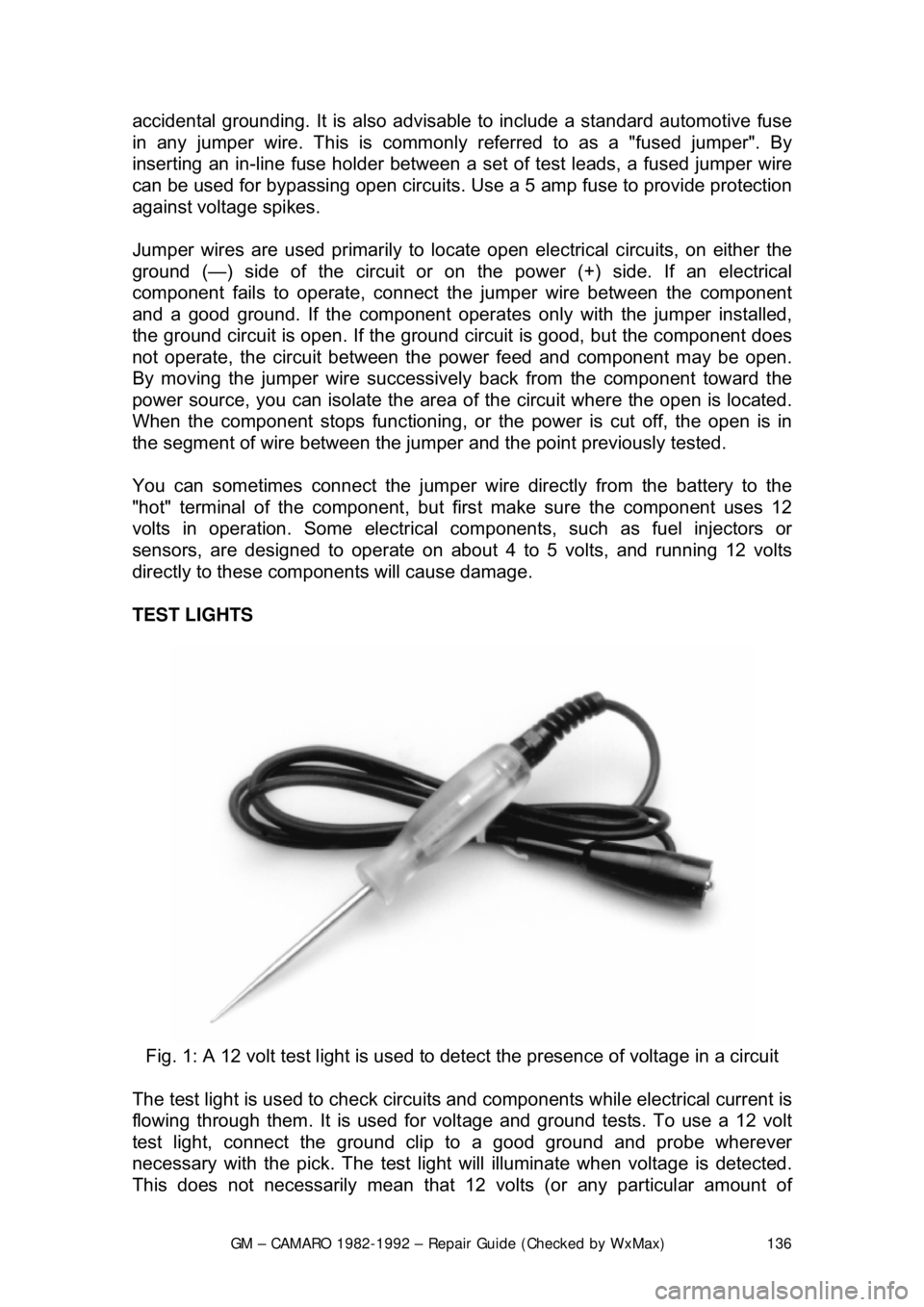
Fig. 1: A 12 volt test light is used to detect the presence of voltage in a circuit
The test light is used to check circuits and components while electrical current is
flowing through them. It is used for volt age and ground tests. To use a 12 volt
test light, connect the ground clip to a good ground and probe wherever
necessary with the pick. The test light will illuminate when voltage is detected.
This does not necessarily mean that 12 volts (or any particular amount of
Page 138 of 875

GM – CAMARO 1982-1992 – Repair Guide (Checked by WxMax) 138
the ground side of the circuit) and
connect the positive lead to the
positive (+) side of the circuit (to t he power source or the nearest power
source). Note that the negative voltme ter lead will always be black and
that the positive voltmeter will alwa ys be some color other than black
(usually red).
• Ohmmeter - the ohmmeter is designed to read resistance (measured in
ohms) in a circuit or component. Mo st ohmmeters will have a selector
switch which permits the measurement of different ranges of resistance
(usually the selector swit ch allows the multiplication of the meter reading
by 10, 100, 1,000 and 10,000). Some ohmmeters are "auto-ranging"
which means the meter itself will dete rmine which scale to use. Since the
meters are powered by an internal battery, the ohmmeter can be used
like a self-powered test light. When the ohmmeter is connected, current
from the ohmmeter flows through the ci rcuit or component being tested.
Since the ohmmeter's internal resi stance and voltage are known values,
the amount of current flow throug h the meter depends on the resistance
of the circuit or component being test ed. The ohmmeter can also be used
to perform a continuity test for suspected open circuits. In using the
meter for making continuity checks, do not be concerned with the actual
resistance readings. Zero resistance, or any ohm reading, indicates
continuity in the circui t. Infinite resistance indi cates an opening in the
circuit. A high resistance reading w here there should be none indicates a
problem in the circuit. Checks for s hort circuits are made in the same
manner as checks for open circuits, ex cept that the circuit must be
isolated from both power and normal gr ound. Infinite resistance indicates
no continuity, while zero resi stance indicates a dead short.
WARNING - Never use an ohmmeter to check the resistance of a component or
wire while there is volt age applied to the circuit
• Ammeter - an ammeter measures the am ount of current flowing through
a circuit in units called amperes or amps. At normal operating voltage,
most circuits have a characteristic amount of amperes, called "current
draw" which can be measured usi ng an ammeter. By referring to a
specified current draw rating, then measuring the amperes and
comparing the two values, one can det ermine what is happening within
the circuit to aid in diagnosis. An open circuit, for example, will not allow
any current to flow, so the amme ter reading will be zero. A damaged
component or circuit will have an incr eased current draw, so the reading
will be high. The ammeter is always connected in series with the circuit\
being tested. All of the current that normally flows through the circuit
must also flow through the ammeter; if there is any other path for the
current to follow, the ammeter readi ng will not be accurate. The ammeter
itself has very little resistance to curr ent flow and, therefore, will not affect
the circuit, but it will measure current draw only when the circuit is closed
and electricity is flowing. Excessive current draw can blow fuses and
drain the battery, while a reduced current draw can cause motors to run \
slowly, lights to dim and other components to not operate properly.
Page 145 of 875

GM – CAMARO 1982-1992 – Repair Guide (Checked by WxMax) 145
When the battery cable(s) are reconnecte
d (negative cable last), be sure to
check that your lights, windshield wipers and other electrically operated safety
components are all working correctly. If your vehicle contains an Electronically
Tuned Radio (ETR), don't forget to also reset your radio stations. Ditto for the
clock.
Page 203 of 875
GM – CAMARO 1982-1992 – Repair Guide (Checked by WxMax) 203
LIGHTING
HEADLIGHTS
REMOVAL & INSTALLATION
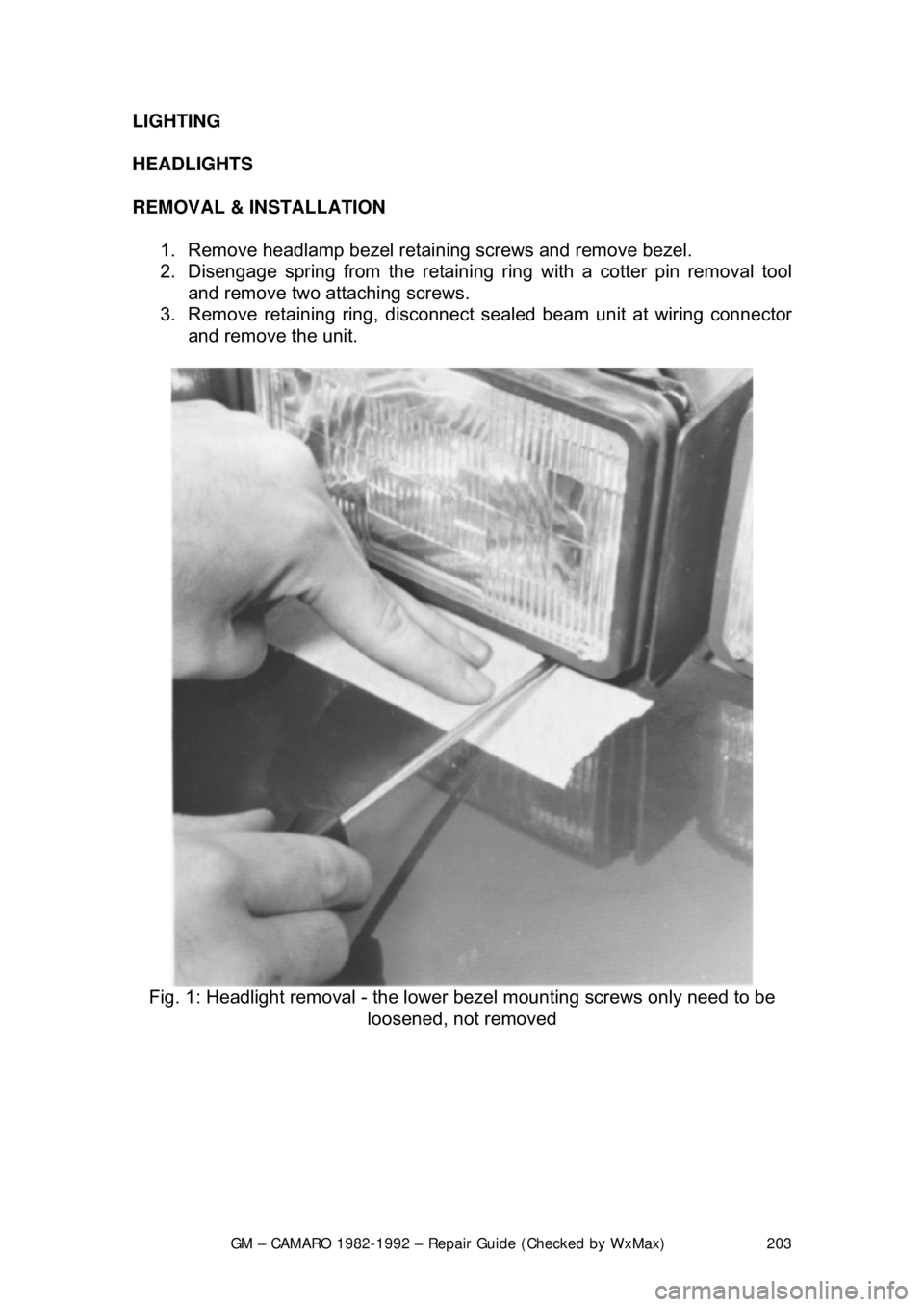
1. Remove headlamp bezel retain ing screws and remove bezel.
2. Disengage spring from the retaini ng ring with a cotter pin removal tool
and remove two attaching screws.
3. Remove retaining ring, disconnect sealed beam unit at wiring connector
and remove the unit.
Fig. 1: Headlight removal - the lowe r bezel mounting screws only need to be
loosened, not removed
Page 205 of 875
GM – CAMARO 1982-1992 – Repair Guide (Checked by WxMax) 205
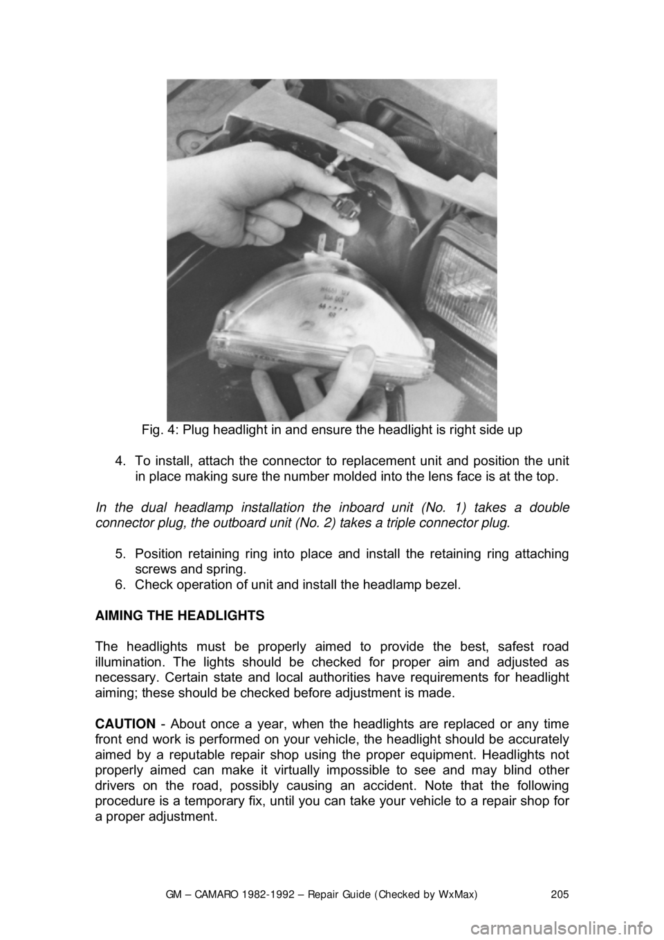
Fig. 4: Plug headlight in and ens ure the headlight is right side up
4. To install, attach the connector to replacement unit and position the unit
in place making sure the number molded in to the lens face is at the top.
In the dual headlamp installation the in board unit (No. 1) takes a double
connector plug, the outboard unit (No. 2) takes a triple connector plug.
5. Position retaining ring into place and install the retaining ring attaching
screws and spring.
6. Check operation of unit and install the headlamp bezel.
AIMING THE HEADLIGHTS
The headlights must be properly aimed to provide the best, safest road
illumination. The lights should be che cked for proper aim and adjusted as
necessary. Certain state and local author ities have requirements for headlight
aiming; these should be check ed before adjustment is made.
CAUTION - About once a year, w hen the headlights are r eplaced or any time
front end work is performed on your vehicl e, the headlight should be accurately
aimed by a reputable repai r shop using the proper equipment. Headlights not
properly aimed can make it virtually impossible to see and may blind other
drivers on the road, possibly causing an accident. Note that the following
procedure is a temporary fix, until you can take your vehicle to a repair shop for
a proper adjustment.
Page 206 of 875
GM – CAMARO 1982-1992 – Repair Guide (Checked by WxMax) 206
Headlight adjustment may
be temporarily made using a wall, as described
below, or on the rear of another vehicle. When adjust ed, the lights should not
glare in oncoming car or truck windshi elds, nor should they illuminate the
passenger compartment of vehi cles driving in front of you. These adjustments
are rough and should always be fine-t uned by a repair shop which is equipped
with headlight aiming t ools. Improper adjustments may be both dangerous and
illegal.
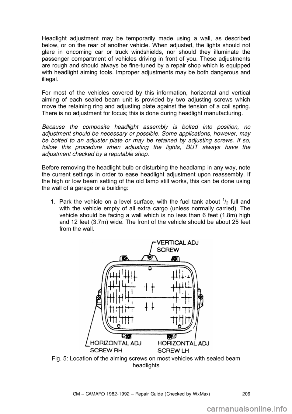
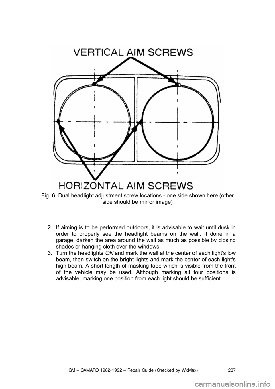
For most of the vehicles covered by th is information, horizontal and vertical
aiming of each sealed beam unit is provided by two adjusting screws which
move the retaining ring and adjusting plat e against the tension of a coil spring.
There is no adjustment for focus; this is done during headlight manufacturing.
Because the composite headlight asse mbly is bolted into position, no
adjustment should be necessary or possibl e. Some applications, however, may
be bolted to an adjuster plate or may be retained by adjusting screws. If so,
follow this procedure when adjusti ng the lights, BUT always have the
adjustment checked by a reputable shop.
Before removing the headlight bulb or di sturbing the headlamp in any way, note
the current settings in order to ease headlight adjustment upon reassembly. If
the high or low beam setting of the old la mp still works, this can be done using
the wall of a garage or a building:
1. Park the vehicle on a level su rface, with the fuel tank about
1/2 full and
with the vehicle empty of all extra cargo (unless normally carried). The
vehicle should be facing a wall whic h is no less than 6 feet (1.8m) high
and 12 feet (3.7m) wide. The front of the vehicle should be about 25 feet
from the wall.
Fig. 5: Location of the aiming screw s on most vehicles with sealed beam
headlights
Page 207 of 875
GM – CAMARO 1982-1992 – Repair Guide (Checked by WxMax) 207
Fig. 6: Dual headlight adjustment screw locations - one side shown here (other
side should be mirror image)
2. If aiming is to be performed outdoors, it is advisable to wait until dusk in
order to properly see t he headlight beams on the wall. If done in a
garage, darken the area around the wall as much as possible by closing
shades or hanging cloth over the windows.
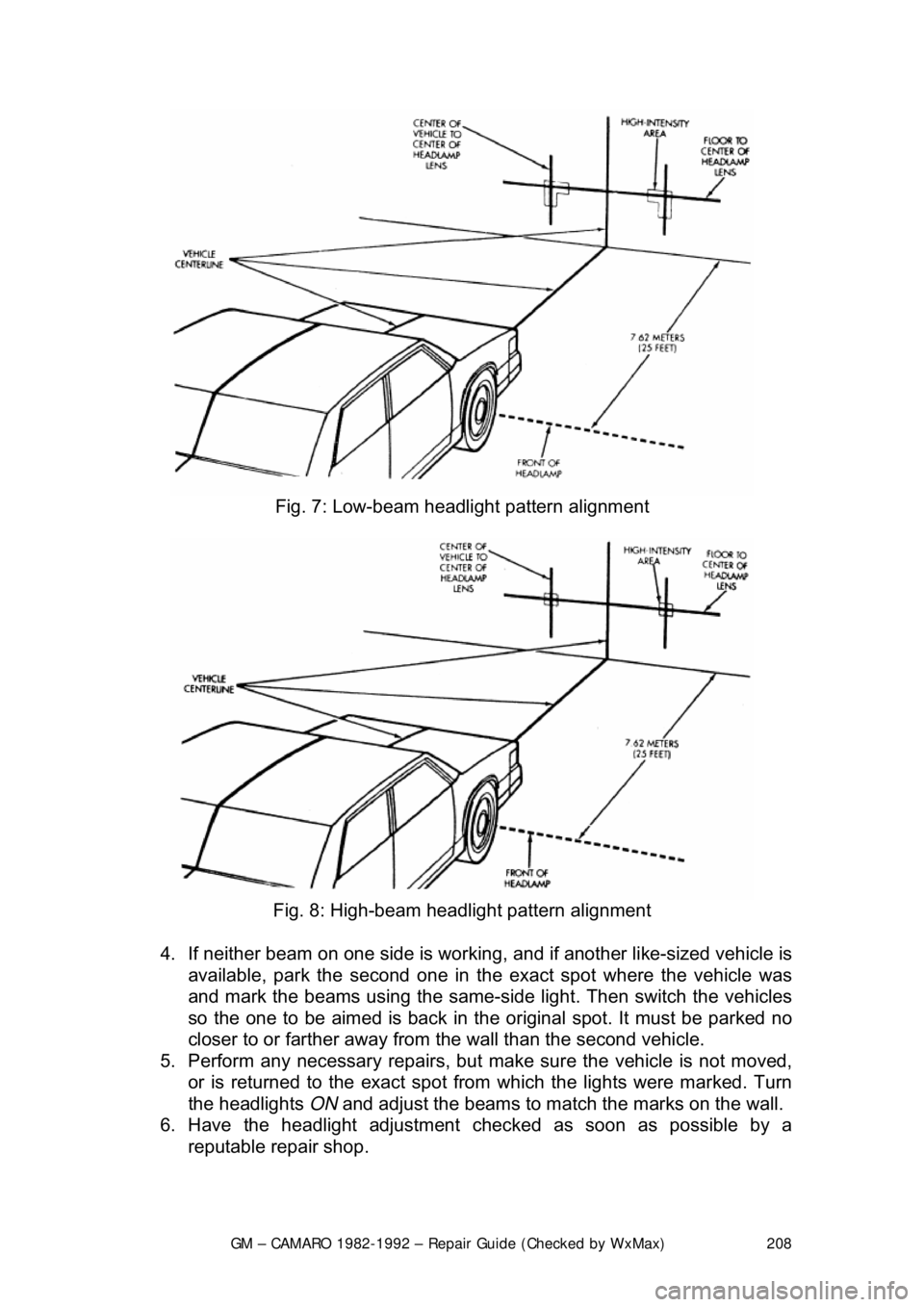
3. Turn the headlights ON and mark the wall at the center of each light's low
beam, then switch on the bright lights and mark the center of each light's
high beam. A short length of masking tape which is visible from the front
of the vehicle may be used. Althoug h marking all four positions is
advisable, marking one position from each light should be sufficient.
Page 208 of 875
GM – CAMARO 1982-1992 – Repair Guide (Checked by WxMax) 208
Fig. 7: Low-beam headlight pattern alignment
Fig. 8: High-beam headlight pattern alignment
4. If neither beam on one side is working, and if another like-sized vehicle is
available, park the sec ond one in the exact spot where the vehicle was
and mark the beams using the same-si de light. Then switch the vehicles
so the one to be aimed is back in the or iginal spot. It must be parked no
closer to or farther away from the wall than the second vehicle.
5. Perform any necessary repairs, but ma ke sure the vehicle is not moved,
or is returned to the exact spot from which the lights were marked. Turn
the headlights ON and adjust the beams to matc h the marks on the wall.
6. Have the headlight adjustment c hecked as soon as possible by a
reputable repair shop.