fuel cap CHEVROLET CAVALIER 1984 1.G Owners Manual
[x] Cancel search | Manufacturer: CHEVROLET, Model Year: 1984, Model line: CAVALIER, Model: CHEVROLET CAVALIER 1984 1.GPages: 105, PDF Size: 24.23 MB
Page 34 of 105
Downloaded from www.Manualslib.com manuals search engine When_ going up or down hills. it ~ ~ tor the vehk:1e to toM 011 to gain apHCI (.,.rticu"Y when towing I trailer), even though the Cruise Control is enpgecL • this happens while going up hin, merely depress the accelerator pedal to maintain the speed desired. If going down a hili steep enough to cau .. thl vehie'" to gain speed, depress the brake pedal •• which will both dl .. ngage the Cruise Control and help .lOw the vehicle. In addition, when going down a steep or lang grade . the transaxle shoUld be shifted into I lower gear to help control vehicte speed •• see "Descending A Grade " in "Starting and Operating," Section 2.
HORN
The horn on your vehicle is actuated by firmly pressing on the ped in the
center of the steering
wheel.
HAZARD WARNING FLASHER
The hazard warning flasher is covered in "In Case of Emergency," Section 3.
FLOOR CONTROLS
BRAKING SYSTEM
The regular braking system is designed for braking performance under a wide
range of driving cond~ions even when the vehicle is loaded to ~ lull rated
vehicle toad capacity .
CAUTION: Driving through water deep enough to wet brake components may cau .. the brakea nat to work .. welL -M a reaul, the vehIde wi. not aIow down .. the usu.I _, ond M may pull 10 "'" right Of ..... _ 0"'-""'11 to "'" _ tor _ .-.os,
-'1 "'" ...... lightly 10 check __ .... "-'"
Brake Warning lJg/rt
The brake system warning light is covered in the '.' lnstrumentPanel" section.
Vacuum Power Brakes
• the engine stops, do not pump the brakes. The system is designed to stop the vehicle with reserve power assist n the brake pedal is held dOwn. This
reserve is
greatly reduced each time you apply and release the brakes. II,
when you turn the atMring wheel during braking, the vehic:1e does not turn, don't push as hard on the brake pedal •.
Without power assist the vehicle can still be stopped by pushing much harder
on the brake
pedal. however. the stopping distance may be longer.
Brakes (Except ,Parking Brake)
H the brake pedaJ goes down farther than normal, ~ may be due to a lack of
adjustment of any rear drum
brakes. To find. out if this is the case. drive
backward and forward a few times. applying the brakes firmly when going in
each direction.
See your dealer n pedal height dOes not retum to normal, or there is a rapid
increase in pedal travel whether or not your vehicle has rear drum brakes. This
could be a sign of brake trOUble.
NOTICE: "FtidInsI the brake" by resting yow i0oi on thl brau pedal when you do not Intend 'to brake CIIf1 overhMI: the brIkM and ...... out the brake InInga and p..ts faster. , ThI. mIIy alSo dllNlge the brakes Mtd will wasta fuel.
2-18
Page 43 of 105
Downloaded from www.Manualslib.com manuals search engine • HEATER --In this position, most of the air is delivered to the floor air outlet
with a small amount delivered to the windshield (defroster outlets). The air
temperature
Is controlled by the TEMPERATURE LEVER while the air
quantity
is controlled by the FAN LEVER. This position is used for most winter driving.
• BLEND -- The AIR SELECTOR LEVER may be adjusted between HEATER
and DEFROST positions to obtain a variable distribution of air between the
floor air outlet and the windsh ield defroster air outlets.
• Side window defogger air outlets direct air to the side windows whenever
the fan is operating.
•
DEFROST - -In this poSition, most of the air is delivered to the windshield
(defroster outlets) with a small amount
to the floor air outlet.
The windshield defrosting and defogging system assists in providing
good visibility through designated areas of the windshield under most inclement
weather conditions . For immediate operation of the vehicle, the windshield
should be scraped clear.
Operate system for 30 seconds before switching to DEFROST . This will
remove humid air from the system
and minimize rapid fogging of the glass
which can occur if humid air Is blown onto a cOol windshield .
AIR CONOmONING SYSTEM
This system combines heating and cOOling capabilities for comfort in all weather conditions.
During some air conditioning operating conditions, slight increases and
decreases of engine speed/power may be noticed . This
should be considered
normal, as the system is designed to cycle the compressor
ON and OFF to
maintain desired cooling. The reduced compressor operation should
benef~ fuel economy.
Fan Lever
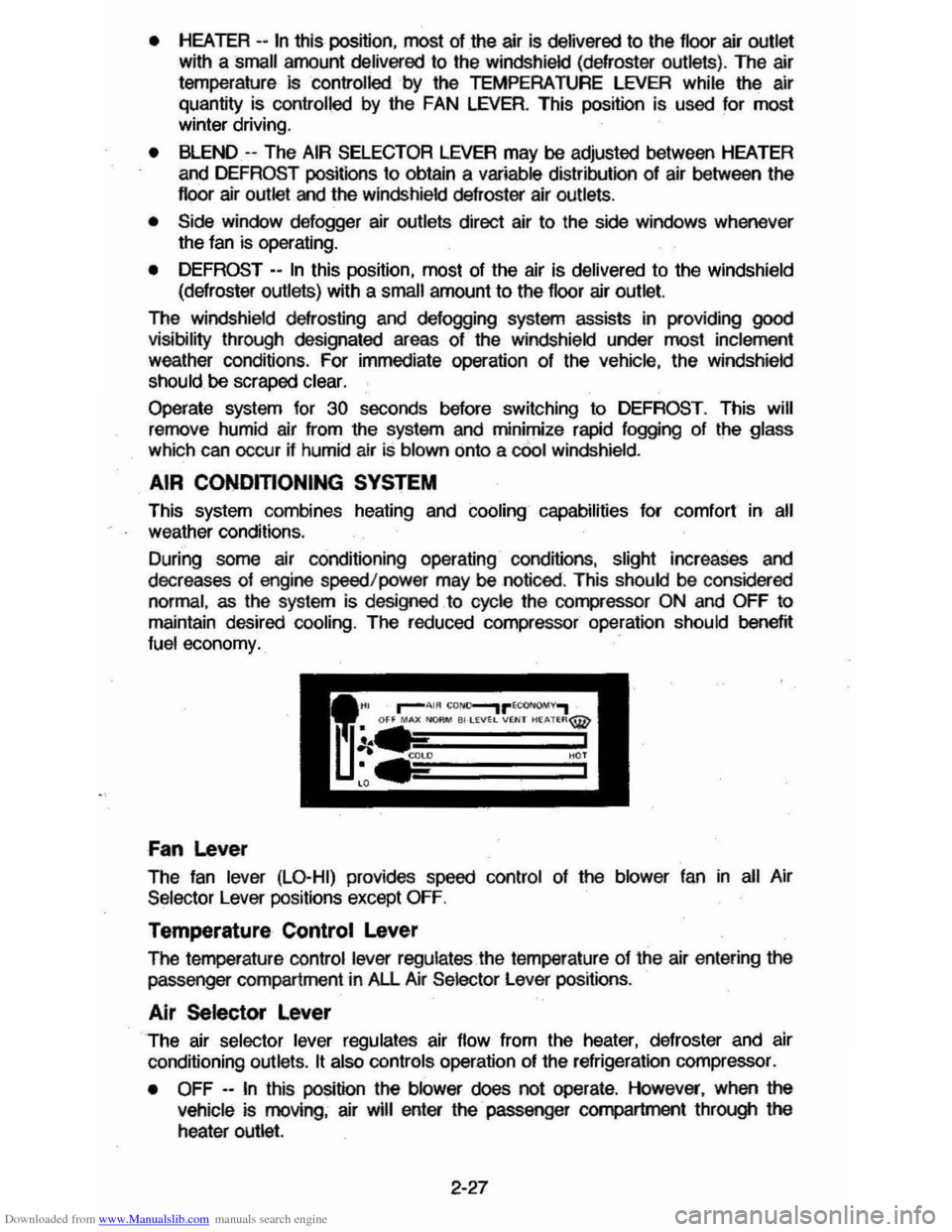
The fan lever (LO-HI) provides speed control of the blower fan in all Air
Selector Lever positions except
OFF.
Temperature Control Lever
The femperature control lever regulates the temperature of the air entering the passenger compartment in All Air Selector Lever positions .
Air Selector Lever
The air selector lever regulates air flow from the heater, defroster and air
conditioning outlets.
It also controls operation of the refrigeration compressor.
•
OFF --In this position the blower does not operate . However, when the
vehicle is moving, air will enter the· passenger compartment through the
heater outlet.
2-27
Page 65 of 105
Downloaded from www.Manualslib.com manuals search engine 3. Install wheel and tire assembly and install hub cap by pushing or hitting
into place (the wheel can be mounted with hub cap in place). The hub cap
must be oriented by engaging the bump on the side of the hub cap
retention tab with the cutout on the side of the wheel pilot hole.
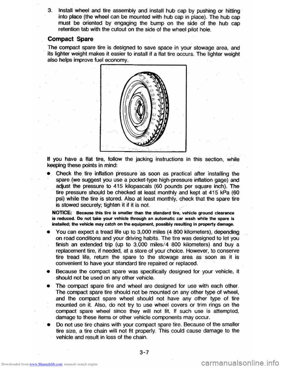
Compact Spare
The compact spare tire is designed to save space in your stowage area, and
its lighter weight makes it easier to install if a flat tire occurs. The lighter weight also helps improve fuel economy. ~--~------~~
" you have a flat tire, follow the jacking Instructions in this section, while keepingihese points in mind:
• Check the tire inflaiionpressureas soon as practical after installing the
spare (we suggest you use a 'pocket-type high'pressure inflation gage) and
adjust the pressure to 415
kilopascals (60 pounds per square inch). The
tire pressure should be checked at least monthly and kept at 415 kPa (60
psi) while the tire is stored . Also at least monthly , ·qheck that the spare lire is stowed securely ; tighten it if ~ is not.
NOTICE: Bee ... this tire is smaller than the standard tire, vehicle ground clearance is reduced. Do not take your vehicle through an automatic car wash while ~ spare I. Installed; the vehicle may catch on the equipment, possibly resulting In property damag_.
• YOU can expect a tread life up to 3,000 miles (4 800 kilometers), dependiQg on road conditions and your driving habits. The tire was designed to let you
finish an extended trip (up to 3,000 miles/4 800 kilometers) and buy a replacement tire, -if needed, at a store of your choice. However, to conserve
tire tread ~fe, return the spare to the stowage area as' soon as it is
convenient to have your standard tire repaired or replaced.
• Because the compact spare was specnically designed for your vehicle , ~ should not be used on any other vehicle.
• The compact spare tire and wheel are designed for use with each other.
The compact spare tire should not be mounted on any other type of wheel, and the compact spare wheel should not have any other type of tire
mounted on it. Also, do not try to use wheel covers or trim rings on the
CQr1l>aCt spare whe el since they will not fit. If such use is attempted,
damage to tIlese items or other vehicle components may occur.
• Do not use tire chains with your :compact spare tire. Because of the smaller tire size, a tire chain will not fit properly. This could cause damage to the
vehicle and result in loss of the chain.
3-7
Page 74 of 105
Downloaded from www.Manualslib.com manuals search engine SECTION 5
SERVICE AND MAINTENANCE
Your authorized dealer has factory trained technicians and Genuine GM Parts
to service your vehicle properly_ For expert advice and quality service, see your authorized dealer.
CAUTION: As with any machine, take care when making any check, doing any maintenance, or making any repair, to avoid being injured. Some of the MATERIALS in this vehicle may also be hazardous if used, serviced, or handled improperly. Improper or incomplete service can affect the vehicle itself which may in turn result in personal
injury, or damage to the vehicle or its equipment. H you have ANY question about carrying out some service, have the work done by a skilled technician.
REPLACEMENT FASTENERS
During vehicle maintenance, any fasteners used to replace older ones must
have the same measurements and strength as those removed, whether metric or customary. (The numbers on the heads of rnetric bons and on the surfaces
of metric nuts show their strength. Customary bolts use radial lines to show
this,
while most customary nuts do not have strength markings.) Fasteners
taken from the vehicle should be saved for re-use in the same spot when
possible. Where a fastener cannot be used again, take care to choose a
replacement that matches the old one. For information and help, see your
authorized dealer.
CAUTION: This vehicle is primarily dimensioned In the metric system. Most fasteners
are metric and many are very close in dimension to well· known customary fasteners in the inch system. Mismatched or incorrect fasteners can result in damage to the vehicle or possibly personal injury.
MAINTENANCE SCHEDULE
For owner convenience, a separate folder ,has. bee" providef;1 with your vehicle which outlines the maintenance your vehicle requires. The Maintenance
Schedule folder is supplemented by this section of the Owner's Manual.
Read this publication for a full understanding of your vehicle's maintenance
needs.
If you need a replacement Maintenance Schedule, see your dealer or contact the . Consumer . Aelations Representative, . Chevrolet Central Office,
Chevrolet Motor Division, Warren, MichigarL4809ll-13t~2-550Q1 (In Canada, contact the Customer Services Representative, General MotorsoT---
Canada LId., Oshawa, Ontario, L1J 5Z6; 416/644-6624).
FUEL CAP
The fuel cap is located behind a hinged door on the right'rear fender. For your
convenience there
is a fuel cap hanger located on the filler door.
The
fuel tank filler cap has a "s£rew-on ratcheting type" feature.
• To remove -rotate cap counterclockwise to clear the inside of the filler
neck. This will allow any residual pressure to escape.
• To install - reverse this procedure and tighten cap securely until a
"ratcheting",
clicking sound is heard indicating cap is on properly.
5-1
Page 75 of 105
Downloaded from www.Manualslib.com manuals search engine NOTICE: H you need to replace the fuel cap, use only a cap specified for your model. An incorrect fuel cap can result in a serious maHunction of the fuel system or emission control system. You can get a correct replacement cap from your dealer.
CATALYTIC CONVERTER
The catalytic converter is an emission control device added to the exhaust system to reduce exhaust gas pollutants. The converter contains
a ceramic material coated with noble metal catalysts. To prevent contamination
and loss of effectiveness of the catalysts. unleaded gasoline must be used.
Unleaded
gasoline also reduces spark plug fouling, exhaust system corrosion and engine oil deterioration. Leaded gasoline will also damage the oxygen
sensor
in the Computer Command Control system which could affect emission
control.
To help prevent damage:
1. Keep your engine properly maintained. Engine malfunctions involving the
electrical, carburetion, electronic fuel injection or ignition systems may
result in unusually high catalytic converter and exhaust system
temperatures which, under extreme malfunctioning conditions, may ignite
interior floor ·covering materials above the converter. Do not keep driving
your vehicle if you detect engine misfire, noticeable loss of
performance, or other unusual operating conditions. Instead, have it
serviced promptly. See the Maintenance Schedule folder for information on inspecting and maintaining the engine, exhaust system, and other
components.
2. Do not push or tow this vehicle to start it. This may result in unusually
high catalytic converter
and exhaust system temperatures which under
extreme conditions may ignite interior floor-covering material above the
converter.
Disregarding these instructions
could damage the catalytic converter, the vehicle, or nearby property and affect warranty coverage.
COMPUTER COMMAND CONTROL SYSTEM
Most vehicles sold in the United States (and some vehicles sold in Canada)
have the Computer Command Control system.
The Computer Command Control system monitors the exhaust stream with
an oxygen sensor. Based on sensor signals, the electronic control module adjusts
the air-fuel ratio
as needed. It is very important to use only unleaded
gasoline in vehicles equipped with the Computer Command Control system.
Leaded gasoline will damage the oxygen sensor,
and may affect emission
control.
"Check Engine" Light
Most vehicles sold in the United States (and some vehicles sold in Canada)
have the Computer Command Control system.
Vehicles
.with the Computer Command Control system, include a "CHECK
ENGINE" light
on the instrument panel designed to indicate the need for
system service. It will come on during engine starting to let you know the bulb
is working. (The
light will stay on a short time aiter the engine starts.) Have the
system repaired if the "CHECK ENGINE" light does not come on during engine
starting.
If the light comes on, either intermittently or continuously while driving,
service to the Computer Command Control system is required. Although in
5-2
Page 78 of 105
Downloaded from www.Manualslib.com manuals search engine Oil Identification Logo
A logo (symbol) has been developed to help you select the oil you should use,
and it probably will be included on oil cans sometime during 1983. The top
portion of the logo shows the oil quality by API designations such as SF, SFI
CC, or others. The center portion of the logo will probably show the SAE
viscosity grade, such as SAE 5W-30. "Energy Conserving," shown in the lower portion, indicates that the oil has fuel-saving capabilities.
Change Intervals
The oil and oil filter change intervals for your engine are based on the use of
SF-quality oils and high-quality fi~ers such as AC oil filters. Using oil other
than SF-quality, or oil and filter change intervals longer than
recommended could reduce engine life. Damage to engines due to improper
maintenance or use of incorrect
oil quality and/ or viscosity is not covered by
the Chevrolet new car warranties.
Your engine was
filled with a high-quality engine oil when it was built. You do
not have to change this oil before the first recommended change interval.
Oil
and filter change intervals depend upon how you use your vehicle. The
following should assist in determining the proper oil and fi~er change intervals:
TVPEOFUSE CHANGE INTERVAL
• Operating
in dusty areas.
• Towing a trailer.
• Idling for extended periods andlor low speed operation such as found • Change engine oil and filter every
in police, taxi or door-Ie-door de-livery service. 3,000 miles (4 800 kilometers) or 3
rn.onths, whichever comes first.
• Operating when outside tempera-tures-remain below freezing and when most trips are less than 4 miles' (6 kilometers)~
• Operating on a daily basis, as a • Chan:ge engine oil every 7,500 general rule, for several miles and miles (12 000-km) or 12 months,
when none of the above conditions whichev.er comes first. Change en·
apply. gine oil filter at first oil change. then every other oil change if mileage determines· when you change oil. If time determines change intervals, change the filter with each oil change.
Engine Oil Additives
Engine oils contain a variety of additives. Your engine should not need any
extra additives
K you use the recommended oil quality and change intervals. However, H you think your engine has an oil-related problem, a supplemental
additive ("GM Engine Oil Supplement") is available that may solve your problem without causing other difficuHies. Consu~ your dealer who can provide
you
w~h this tested and approved additive.
Used Oil Disposal
Do not dispose of used engine oil (or any other oil) in a careless manner such
as pouring it on the ground, into sewers, or into streams or bodies of water.
Instead, recycle it by taking it to a used oiL collection facility which may be
found
in your area. If you have a problem disposing of your used oil, it is
suggested that you contact your
dealer or a service station.
5-5
Page 81 of 105
Downloaded from www.Manualslib.com manuals search engine The cooting system was filled at the factory with a quality coolant that meets
GM Specifications.
~ is important to use proper coolant to prevent damage to
cooling system components . Coolants meeting GM Specification 1825-M or
those specially formulated for aluminum co"1JOflent protection should be used.
The cooling system is designed to use coolant (a mixture of ethylene glycol ,
corrosion inhibitors and water) rather than plain water. The coolant solution
must be used year round
to provide:
• freezing protection down to -37'C (-34'F),
• boiling protection up to 128 'C (262'F),
• protection against rust and corrosion in the cooling system,
• the proper engine temperature for efficient operation and emission control,
and
• proper operation of the coolant temperature light or gage .
See the Maintenance Schedule folder to find out when the coolant must be
replaced . Note that changing the coolant is needed
to make certain that all
parts
of the cooling system work well.
.-~~~~--~-.
CooUng System Care
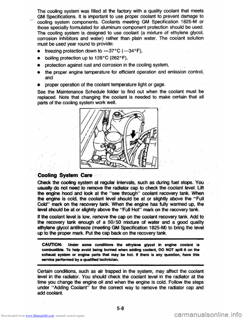
Check the cooling system at regular intervals, such as during fuel sI
Cold' .' mark on the recovery ' tank. When the engine has fully warmed up, the
level should be at or slightly above the "Full Hot" mark on the recovery tank.
H·the coolant level is low, remove the cap on the coolant recovery tank. Add to the recovery tank enough of a SO/ SO mixture 01 water and a good quality
eIIlyIene gIyool antifreeze (meeting GM SpecWication 1825-M) to bfing the level
"" to the proper mark. Pui the cap back on the recovery tank.
CAUTION: Under some' condttlons . the ethytene glycol In engine' coolant is combultlble. To help Rold being burMCf when adding eoollnt, DO NOT spill It on the exhliUlt system or engine ~rtI tMt mIIy be haL tf there It any question,' have this .....,ice performed by .• quallftecl t.chnlclan.
Certain conditions, such as air trapped in the system, may effect the coolant level in the radiator . You should check the coolant level in the radiator at the
time you change the engine 011 and when the engine Is cold. Follow the steps
under
"Adding Coolant" for the correct way to remove the radiator cap and add coolant.
5-8
Page 86 of 105
Downloaded from www.Manualslib.com manuals search engine /" VEHICLE CAPACITY OCCUP."TS COLD TIRE PRESSURE ' , ~~, mT CtR RR TOTAL C_, ~E~R
MAX [ LOAD I [ 1
A A TIRE [ I
.. T"ES AAf ,.qT ,~o ... OONiNG '00' "50 ". 'P" TO THE'" SIZE R'V,""ME>.<:lEl) PR"5lJRES
SPARE TIRE ,
SIZE ( )
MAXIMUM LUGGAGE/CARGO LOAD CAPACITY
Coupe and Sedan Station Wagon 60.0 kg/' 321bs. 40.0 kg/88Ibs.
Notice: Total combined weight of luggage compartment load, luggage rack load (when equipped), trailer tongue load, non-factory installed options and
passenge'rs' must. not exceed the vehicle capacity weight (shown on the tire placard located on the driver's door).
Inflation Pressure
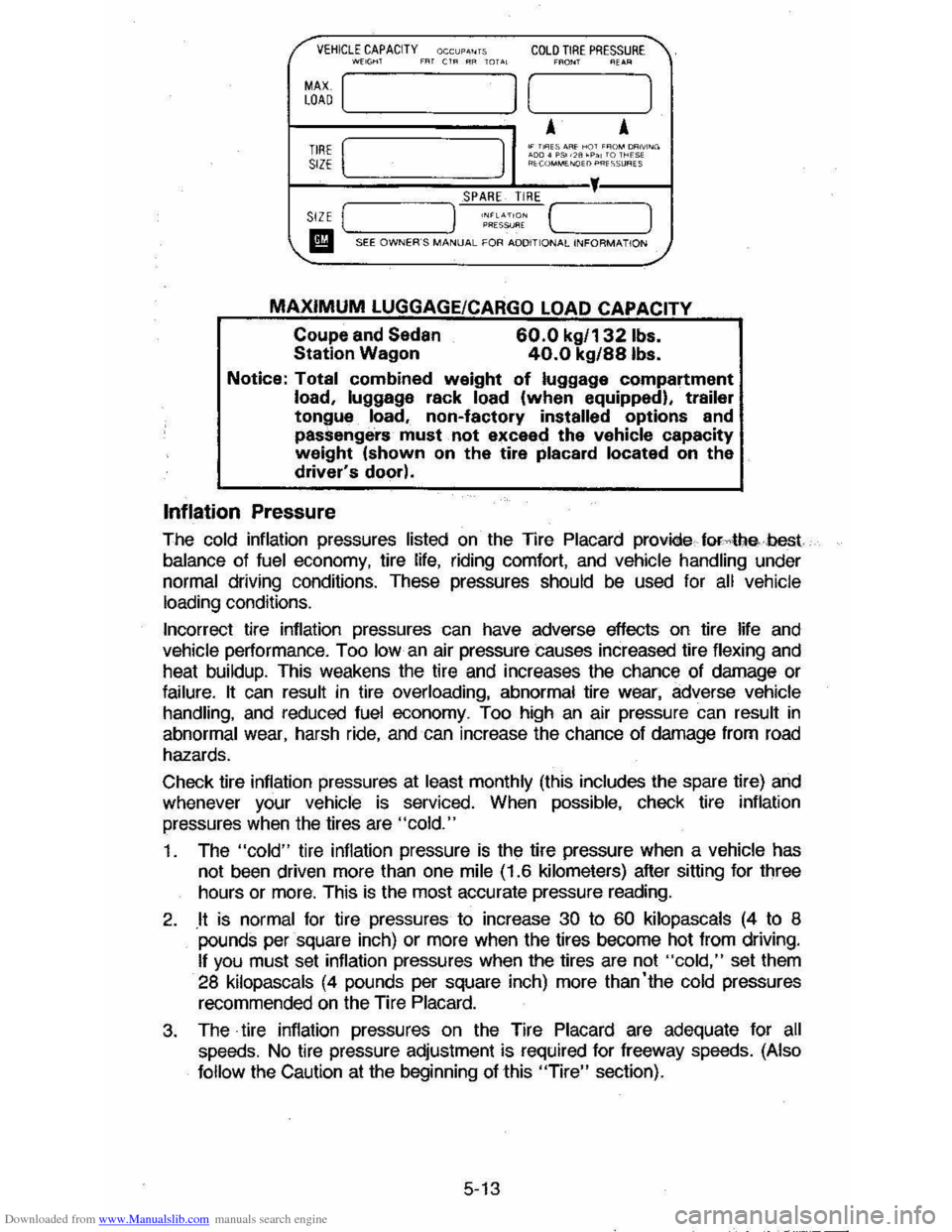
The cold inflation pressures listed on the Tire Placard provide forAIlebest
balance of fuel economy, tire life, riding comfort, and vehicle handling under normal driving conditions. These pressures should be used for all vehicle
loading conditions.
Incorrect tire inflation pressures can have adverse effects on tire life
and vehicle performance. Too Iowan air pressure causes increased tire flexing and
heat buildup. This weakens the tire and increases the chance of damage or
failure. It can result in tire overloading, abnormal tire wear, adverse vehicle handling, and reduced fuel economy. Too high an air pressure can result in
abnormal wear, harsh ride, and can increase the chance of damage from road
hazards.
Check tire inflation pressures at
least monthly (this includes the spare tire) and
whenever your vehicle is serviced. When possible, check tire inflation
pressures
when the tires are "cold."
1. The "cold" tire inflation pressure is the tire pressure when a vehicle has
not been driven more than one mile (1.6 kilometers) after sitting for three
hours or
more. This is the most accurate pressure reading.
2. .It is normal for tire pressures to increase 30 to 60 kilopascals (4 to 8 pounds per square inch) or more when the tires become hot from driving.
If you must set inflation pressures when the tires are not "cold," set them
28 kilopascals (4 pounds per square inch) more than'the cold pressures
recommended on the Tire Placard.
3. The· tire inflation pressures on the Tire Placard are adequate for all speeds. No tire pressure adjustment is required for freeway speeds. (Also
follow
the Caution at the beginning of this "Tire" section).
5-13
Page 92 of 105
Downloaded from www.Manualslib.com manuals search engine SECTION 6
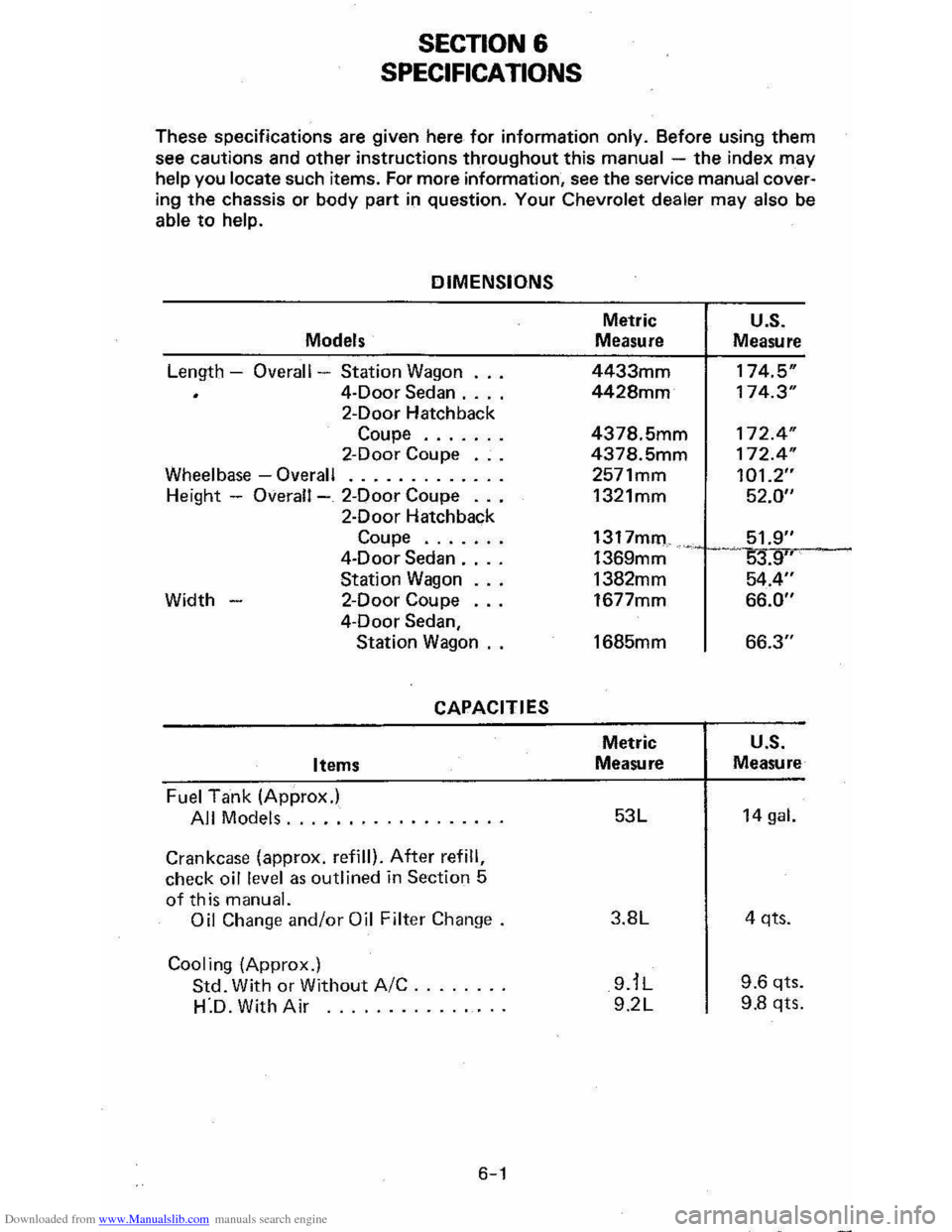
SPECIFICATIONS
These specifications are given here for information only. Before using them
see cautions and other instructions throughout this manual -the index may help you locate such items. For more information, see the service manual cover·
lng the chassis or body part in question. Your Chevrolet dealer may also be
able to help.
DIMENSIONS
Models
Length -Overall -Station Wagon
4-Door Sedan .... 2-Door Hatchback
Coupe ...... . 2-Door Coupe .. .
Wheelbase -Overall ............ . Height -Overall-_ 2-Door Coupe .. .
2·Door Hatchback
Coupe ...... .
4-Door
Sedan ... .
Station
Wagon Width - 2-Door Coupe ...
4·Door Sedan,
Station Wagon ..
CAPACITIES
Items
Fuel Tank (Approx.)
All Models ................. .
Crankcase (approx, refill). After refill, check oil level as outlined in Section 5
of this manual. Oil Change and/or Oil Filter Change.
Cooling (Approx.)
Std. With or Without AIC ...••... H·D. With Air ...........•...
6-1
Metric
Measure
4433mm
4428mm
4378.5mm
4378.5mm
2571mm
1321mm
1317mm 1369mm
1382mm
1677mm
1685mm
Metric
Measure
53L
3.8L
9.iL 9.2L
-
U.S. Measure
174.5"
174.3"
172.4 "
172.4"
101.2" 52.0"
51.9" 53.9" 54.4"
66.0"
66.3"
U.S. Measure
14 gal.
4 qts.
9.6 qts.
9.8 qts.
Page 98 of 105
Downloaded from www.Manualslib.com manuals search engine CONSUMER INFORMATION -
VEHICLE STOPPING DISTANCES
INTRODUCTION
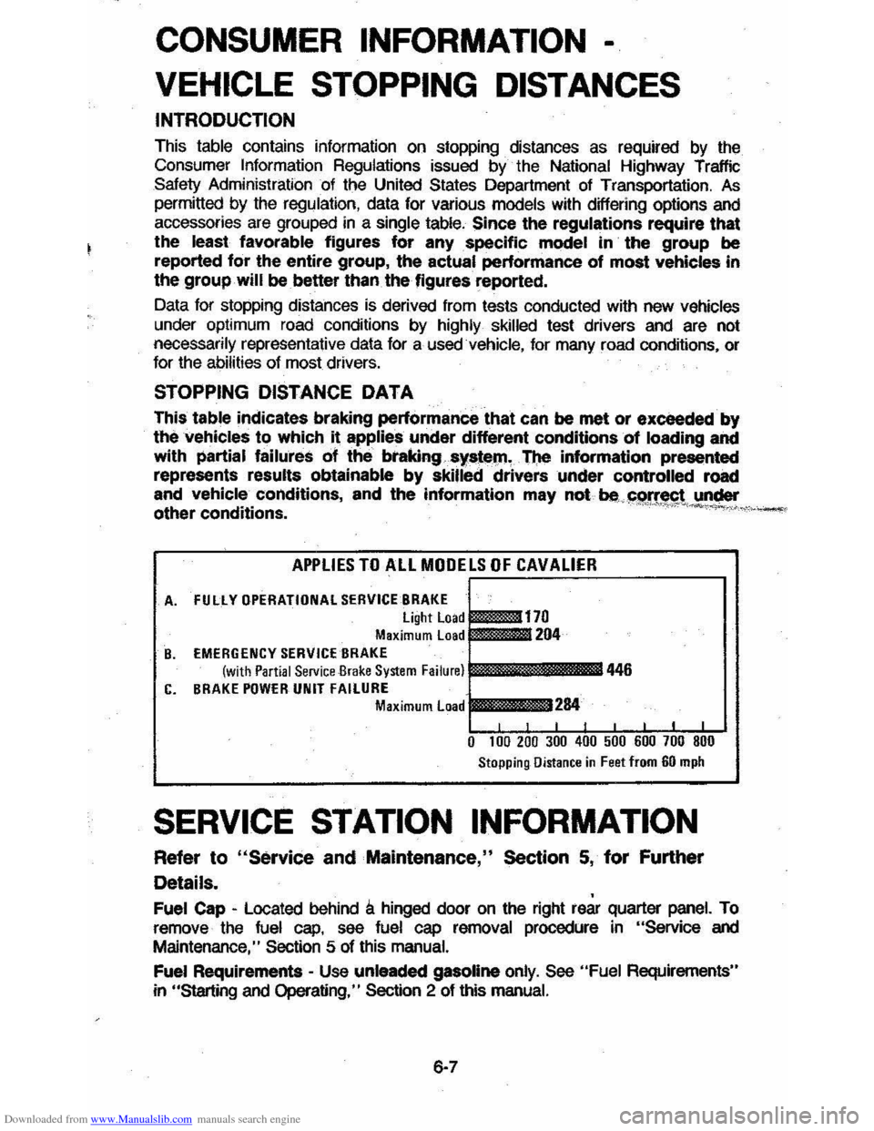
This table contains information on stopping distances as required by the
Consumer Information Regulations issued by the National Highway Traffic
Safety Administration of the United States Department of Transportation, As permitted by the regulation, data for various models with differing options and
accessories are grouped in a single table, Since the regulations require that
the least favorable figures for any specific model in the group be
reported for the entire group, the actual performance of most vehicles in
the group will be better than the figures reported.
Data for stopping distances is derived from tests conducted with new
vehicles
under optimum road conditions by highly skilled test drivers and are not necessarily representative data for a used vehicle, for many road conditions. or for the abilities of most drivers.
STOPPING DISTANCE DATA
This table indicates braking performance that can be met or exceeded by
the vehicles to which it applies under different conditions of loading and
with
partial failures of the brakingsy"tl>l)'I, TI)e information prl>S8nted represents results obtainable by skilled drivers under controlled road
and
vehicle conditions, and the information may not be. !1e!!~t under
other conditions. " --"M.v,,>_.
APPLIES TO ALL MODELS OF CAVALIER
A. FUllY GPERATIGNAl SERVICE BRAKE
~170 light Load Maximum Load 204 B. EMERGENCY SERVICE BRAKE (with Partial Service Brake System Failure) 446 C. BRAKE PGWER UNIT FAilURE Maximum Load I 284 ,
0 100 200 300 400 500 600 700 800
Stopping Distance in Feet from 60 mph
SERVICE STATION INFORMATION
Refer 10 "Service and Mainlenance," Section 5, for Further
Details.
Fuel Cap -Located behind Ii hinged door on the right rea. quarter panel. To
remove the fuel cap, see fuel cap removal procedure in "Service and
Maintenance," Section 5 of this manual.
Fuel
Requirements -Use unleaded gasoline only. See "Fuel Requirements"
in "Starting
and Operating," Section 2 of this manual.
6·7