CHEVROLET CORVAIR 1986 2.G Service Manual
Manufacturer: CHEVROLET, Model Year: 1986, Model line: CORVAIR, Model: CHEVROLET CORVAIR 1986 2.GPages: 56, PDF Size: 22.23 MB
Page 41 of 56
Downloaded from www.Manualslib.com manuals search engine Also, all hoses, fittings and the inlet air filter should be
inspected, cleaned and replciced if necessary.
NOTE: If the positive crankcase ventilator valve should
become
dogged, the engine idle will be adversely
affect~d. Therefore, if the engine idle becomes too slow
or rough, the ventilator valve should be checked before
any carburetor ad;ustments are made to compensate for
the trouble.
AIR INJECTION REACTOR (A.I.R.l
The Air
Injection Reactor system is designed to re
duce .air pollution caused by exhaust emissions. It is entirely separate from the Positive Crankcase Ventilating
system. The Air
Injection Reactor system operates by
oxidizing (or burning) the
hydrocarbons and carbon
monoxide as they are expelled from the combustion
chamber into the exhaust. A positive displacement air
pump, driven by the engine, compresses clean frltered
air, which
is distributed and injected at the exhaust part
of each cylinder. This fresh air mixes with the hot exhaust
gases and promotes further oxidation (or burning) of
both hydrocarbons and carbon monoxide by converting
some
of them to carbon dioxide and water. This does not
reduce the danger of inhaling carbon monoxide in con
frned areas. See page 7 for carbon monoxide warning.
Supplementing
the air pump a special carburetor and
distributor plus related components are required.
The Air
Injection Reactor system should have the A.I.R. pump filter serviced and the drive belt inspected
for
wear and tension every 12 months or 12,000 miles,
38
whichever occurs frrst. In addition, complete effectiveness
of the system, as well as full power and performance,
depends upon idle speed, ignition timing, and idle fuel
mixture being
set according to specifrcation. A quality
tune-up which includes
these adjustments should be per
formed periodically to assure normal engine efficiency,
operation and performance.
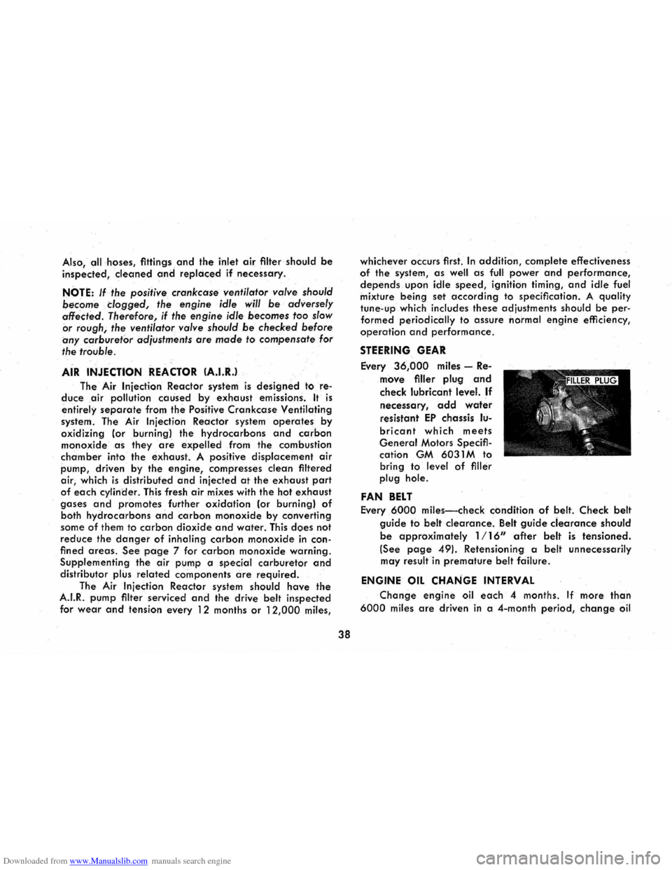
STEERING GEAR
Every 36,000 miles -Re
move frller plug and
check lubricant level. If
necessary, add water
resistant EP chassis lu
bricant which meets
General Motors Specifr
cation GM 6031 M to
bring to level
of frller
plug hole.
FAN BELT
Every 6000 miles-check condition of belt. Check belt
guide to belt clearance. Belt guide ciearance should
be approximately 1/16" after belt is tensioned.
(See page 49). Retensioning a belt unnecessarily
may result
in premature belt fciilure.
ENGINE OIL CHANGE INTERVAL
Change engine oil each 4 months. If more than
6000 miles are driven in a 4-month period, change oil
Page 42 of 56
Downloaded from www.Manualslib.com manuals search engine every 6000 miles. This interval applies to the initial
change as well as subsequent oil changes. The oil
change interval for your Corvair engine is based on the
use
of oils that meet the requirements indicated in the
section on
"Engine Oil Recommendations". Oil change
intervals longer than 4 months or 6,000 miles will result
in serious reductions in engine life and may effect Chev
rolet's
obligation under the provisions of the New Vehicle Warranty.
Certain atmospheric and/or driving conditions includ
ing
prolonged operations at sub-zero temperatures or
under extremely dusty conditions, frequent trailer haul
ing, and extensive idling necessitate more frequent oil
and filter changes. * Operation in dust storms may require
an immediate change of both oil and filter. See your
Chevrolet dealer for advice on frequency of oil and
filter changes because of unusual driving conditions.
A high
quality MS oil meeting General Motors
Standard GM 6041-M was installed in your engine at
the factory. It is not necessary to change this factory
installed oil
prior to the recommended normal change
period. However, the oil level should be checked more
frequently during
the break-in period since somewhat
higher oil consumption is normal until the piston rings
become seated.
*In many such situations, oil change intervals should not exceed 2
months, or 3000 miles, whichever occurs first, and similarly, filter changes should not exceed 4 months or 6000 miles, whichever comes
first.
39
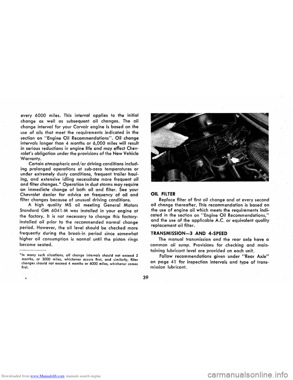
OIL FILTER
Replace filter of first oil change and at every second
oil change thereafter. This recommendation is based on
the use of engine oil which meets the requirements indi
cated in the section on "Engine Oil Recommendations,"
and the use of the applicable AC. or equivalent quality replacement oil filter.
TRANSMISSION-3 AND 4-SPEED
The manual transmission and the rear axle have' a
common
oil sump. Provisions for checking and main
taining lubricant level are provided on each unit.
Follow recommendations given
under "Rear Axle"
on page 41 for inspection intervals and type of trans
mission lubricant.
Page 43 of 56
Downloaded from www.Manualslib.com manuals search engine TRANSMISSION CONTROL LlNKAGE-
3 AND 4-SPEED
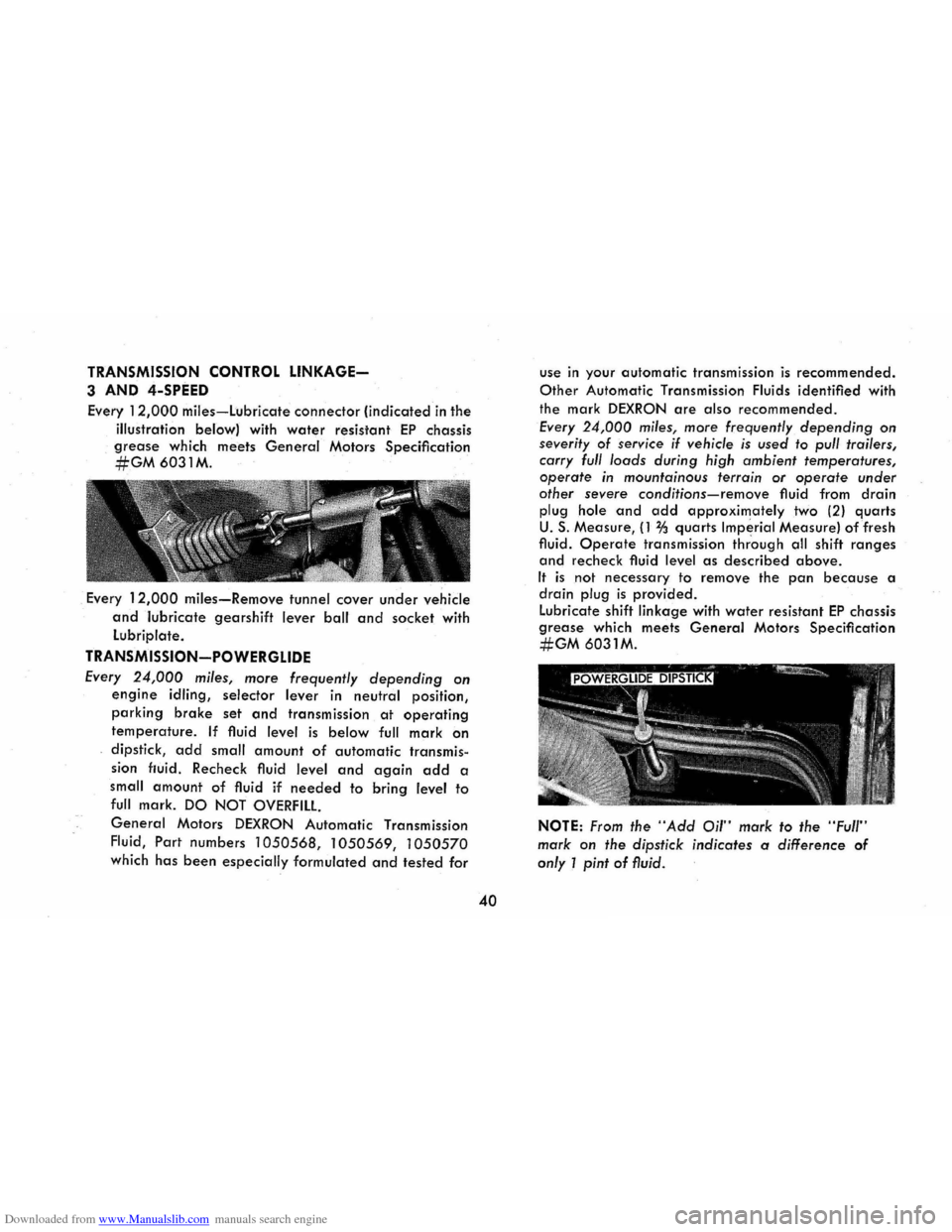
Every 12,000 miles-Lubricate connector (indicated in the
illustration below) with
water resistant EP chassis
grease which meets General Motors Specification
#GM6031M.
. Every 12,000 miles-Remove tunnel cover under vehicle
and lubricate gearshift lever ball and socket with
Lubriplate.
TRANSMISSION-POWERGLIDE
Every 24,000 miles, more frequently depending on
engine idling, selector lever in neutral position,
parking brake set and transmission at operating
temperature. If fluid level is below full mark on
dipstick, add small amount of automatic transmis
sion fluid. Recheck fluid level and again add a
small
amount of fluid if needed to bring level to
full mark. DO NOT OVERFILL
General Motors DEXRON Automatic Transmission
Fluid,
Part numbers 1050568, 1050569, 1050570
which has been especially formulated and tested for
40
use in your automatic transmission is recommended.
Other Automatic Transmission Fluids identified with
the mark
DEXRON are also recommended.
Every 24,000 miles, more frequently depending on
severity of service if vehicle is used to pull trailers,
carry full loads during high ambient temperatures,
operate in mountainous terrain or operate under
other severe
conditions-remove fluid from drain
plug hole and add approximately two (2) quarts
U. S. Measure, (1 % quarts Imperial Measure) of fresh
fluid.
Operate transmission thr'ough all shift ranges
and recheck fluid level as described above.
It is not necessary to remove the pan because a
drain plug is provided .
Lubricate shift linkage with
water resistant EP chassis
grease which meets General Motors Specification
#GM 6031M.
NOTE: From the "Add Oil" mark to the "Full"
mark on the dipstick indicates a difference of
only 1 pint of fluid.
Page 44 of 56
Downloaded from www.Manualslib.com manuals search engine CHASSIS LUBRICATION
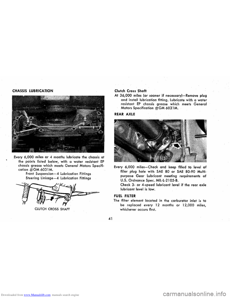
Every 6,000 miles o.r 4 months lubricate the chassis at
the points listed below, with a water resistant EP
chassis grease which meets General Motors Specifi
cation #GM 6031 M. Front Suspension-4 Lubrication Fittings
Steering
Linkage-4 Lubrication Fittings
, WJ~P;=-
CLUTCH CROSS SHAFT
41
Clutch Cross Shaft
At 36,000 miles (or sooner if necessary)-Remove plug
and install lubrication fitting. Lubricate with a water
resistant EP chassis grease which meets General
Motors Specification #GM 6031 M.
REAR AXLE
Every 6,000 miles-Check and keep filled to level of
filler plug hole with SAE 80 or SAE 80-90 Multi
purpose Gear Lubricant meeting requirements of
U.S. Ordnance Spec. MIL-L-21 05-B.
Check 3-or 4-speed lubricant level if the rear axle
lubricant level is low.
FUEL FILTER
The filter element located in the carburetor inlet is to
be replaced every 12 months or 12,000 miles,
whichever occurs first.
Page 45 of 56
Downloaded from www.Manualslib.com manuals search engine AIR CLEANER
CAUTION: In addition to its function of filtering air
drawn into
the engine through the carburetor, the air
cleaner also acts as
a flame arrester in the event the
engine backfires. Because backfiring
may cause fire in
the engine compartment, the air cleaner should be in
stalled at all times unless its removal is necessary for
repair or maintenance services.
Paper Element Type
The oil-wetted paper element is a long-life efficient air
cleaner and should not require replacement before
24,000 miles except under extreme adverse condi
tions .
Inspect air cleaner at 12,000 miles for dust leaks,
holes
or other damage, replace if necessary . If
condition is satisfactory, rotate element 1800 from
originally installed position. Replace
at 24,000 miles.
Under extreme
adverse conditions inspect every 6,000 miles.
Oil Bath Type
Every 12,000 miles-Inspect and clean if necessary.
Refill with SAE 50 engine oil when lowest anticipated
temperature is above freezing; use SAE 20 if below
freezing.
BATTERY (ENERGIZER)
Every 6,000 miles-Clean and oil battery terminals and
oil felt washer. Check fluid level frequently. Keep
filled with distilled water to level of split ring in
42
vent tube. The electrolyte level indicator in the cap
of one cell will glow if the fluid level is low. In this
case each cell should be checked.
CAUTION: Since normal battery or Energizer
chemical action generates hydrogen gas which
is highly explosive when mixed with air, never
expose the battery to an open flame or electric
spark. Also, avoid getting battery fluid, which
is a sulfuric acid solution, on skin, on clothing
or other fabrics, or on painted surfaces . Eye
protection should
be worn while working on the
battery for
any reason.
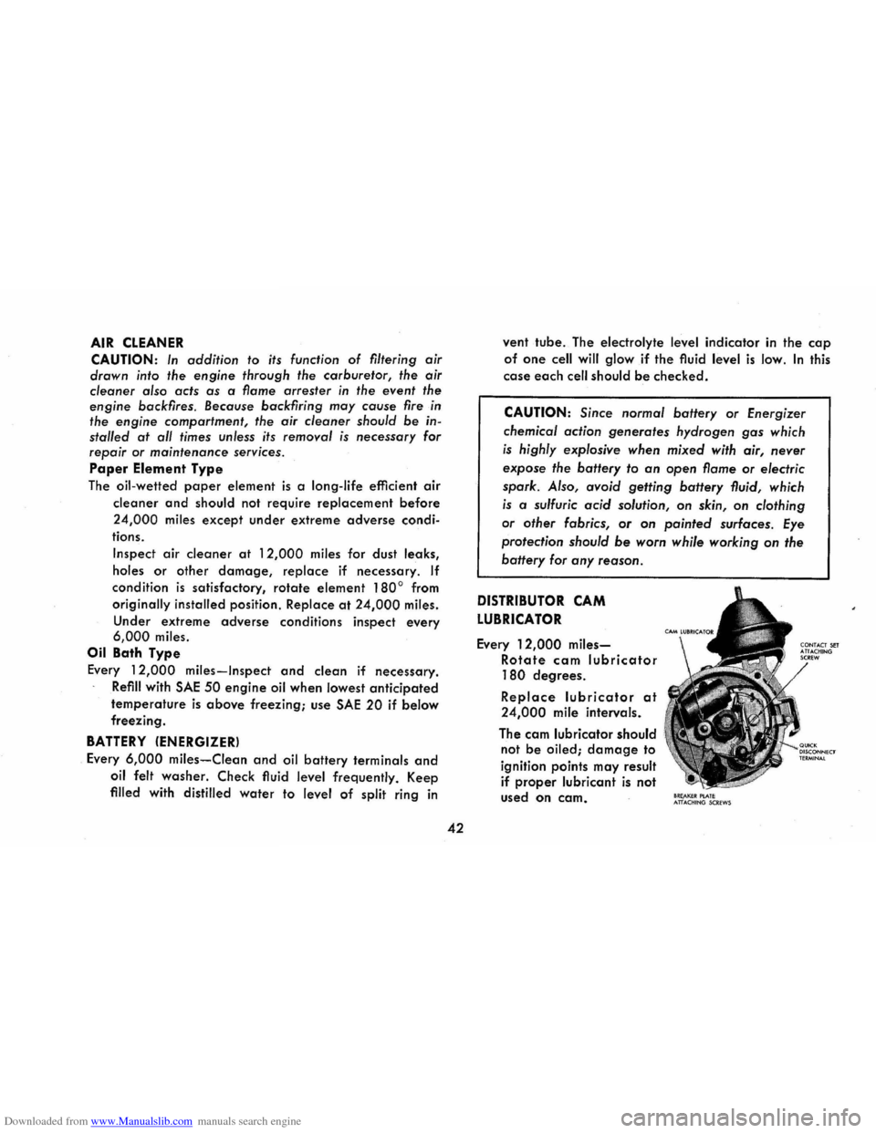
DISTRIBUTOR CAM
LUBRICATOR
Every 12,000 miles
Rotate cam lubricator
180 degrees.
Replace lubricator at
24,000 mile intervals.
The cam lubricator should
not
be oiled; damage to
ignition points may result
if
proper lubricant is not
used
on cam. 8RE,AKEIt PlATE ATTACHtNG SCREWS
Page 46 of 56
Downloaded from www.Manualslib.com manuals search engine AIR CONDITIONING
Have your Chevrolet Dealer check your air conditioning
system
at some time during the winter months to be
sure there has been no loss in cooling output. Dur
ing
the summer, see your Chevrolet Dealer immedi
ately if you suspect the system is not performing as
it should.
BRAKE LININGS
Brake linings should be periodically inspected for wear.
The frequency of this inspection depends upon driv
ing conditions such
as traffic or terrain, and also
the driving techniques of individual owners. Your
Chevrolet Dealer is best qualified to advise you as
to how often this inspection should be performed.
When brakes require relining use genuine General
Motors Parts or equivalent.
BRAKE MASTER CYLINDER
Every 6,000 miles-Check fluid level in each reservoir
and maintain % II below lowest edge of each open
ing with G.M. Hydraulic Brake Fluid Supreme No. 11
PARKING BRAKE AND CLUTCH PULLEYS
AND CABLES
Every 12,000 miles-lubricate pulleys under dash. Re
move. the tunnel cover under vehicle and lubricate
pulleys
and cable bearing points with a water resist
ant EP chassis grease which meets General Motors
43
Specification #GM 6031 M. Lubricate gearshift lever
ball and socket (see page 38) at the same time.
FRONT WHEEL BEARINGS
Clean, repack with high melting point wheel bearing
lubricant, and adjust whenever the wheels and hub
are removed. Replace grease seals at the same time.
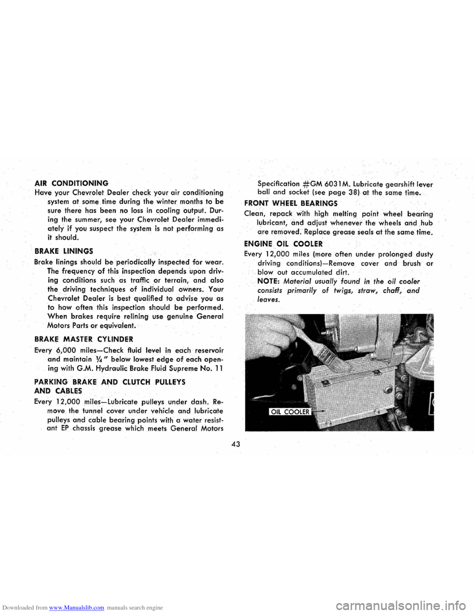
ENGINE OIL COOLER
Every 12,000 miles (more often under prolonged dusty
driving
conditionsl-Remove cover and brush or
blowout accumulated dirt.
NOTE: Material usually found in the oil cooler
consists primarily
of twigs, straw, chaff, and
leaves.
Page 47 of 56
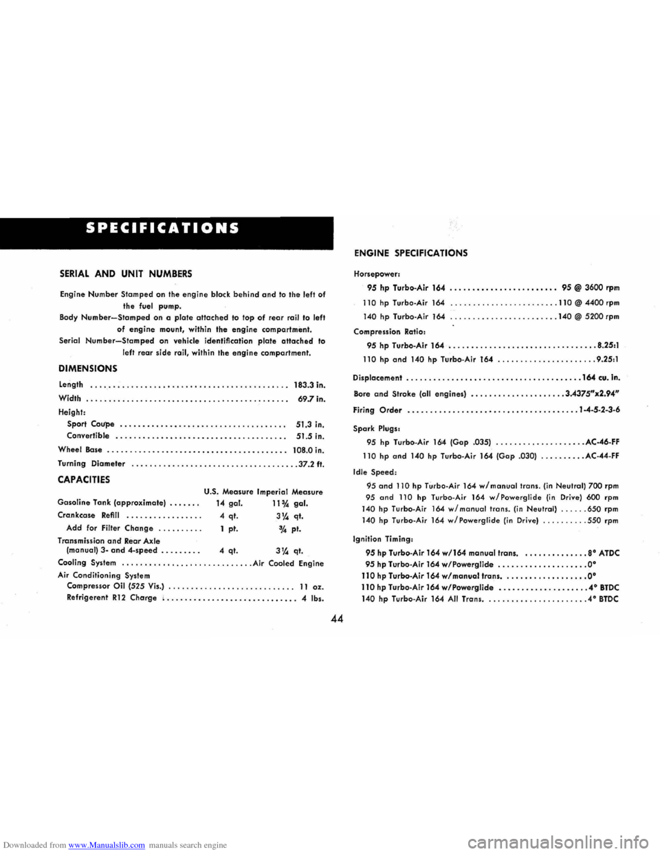
Downloaded from www.Manualslib.com manuals search engine SPECIFICATIONS
SERIAL AND UNIT NUMBERS
Engine Number Stamped on the engine block behind and to the left of
the fuel pump.
Body
Number-Stamped on a plate attached to top of rear rail to left
of engine mount, within the engine compartment .
Serial
Number-Stamped on vehicle identification plate attached to
left
rear side rail, within the engine compartment.
DIMENSIONS
Length .•...............•.•.•..................•... 183.3 in.
Width
.......•....•. . ....•..••......•.............• 69.7 in.
Height: Sport
Coupe ......•...••• ..•..••............•..•• 51.3 in.
Convertible
..........•.....••..•...•............. 51.5 in.
Wheel Base
...................•..•...•.... , ........ 108.0 in.
Turning Diameter .
.•..........•............... ........ 37.2 ft.
CAPACITIES
U.S. Measure Imperial Measure
Gasoline Tank (approximate) ...... .
14 gal. 11 % gal.
Crankcase Refill •....•..... ...... 4 qt. 3~ qt.
Add for Filter Change ......... . 1 pt. 3,4 pt.
Transmission
and Rear Axle
(manual) 3-and 4-speed ........ . 4 qt. 3~ qt.
Cooling System .....••...................... Air Cooled Engine
Air Conditioning System
Compressor Oil (525 Vis.) ...•............. ......... " 11 oz.
Refrigerent
R12 Charge ( •......•................•.... 4 Ibs.
44
ENGINE SPECIFICATIONS
Horsepower:
95 hp Turbo-Air 164 ......••.•.•........•.•• 95 @ 3600 rpm
110 hp Turbo-Air 164 ........................ 110 @ 4400 rpm
140 hp Turbo -Air 164 ........................ 140 @ 5200 rpm
Compression Ratio:
95 hp Turbo-Air 164 •...•........•.•.••••.•...••.•••. 8.25:1
110 hp and 140 hp Turbo-Air 164 ...................... 9.25:1
Displacement
......•....••••••..••••••...•..•.••\
•.•• 164 cu. In.
Bore and Stroke (all engines) ................. .... 3.4375"x2.94"
Firing Order •.........•..•••••••..•.•.••.•\
..••..•. 1-4-5-2-3·6
Spark Plugs.
95 hp Turbo-Air 164 (Gop .035)
.................... AC-46-FF
110
hp and 140 hp Turbo-Air 164 (Gop .030) .......... AC- 44-FF
Idle
Speed:
95 and 110 hp Turbo-Air 164 wi manual trans. (in Neutral) 700 rpm
95
and 110 hp Turbo-Air 164 w/Powerglide (in Drive) 600 rpm
140 hp Turbo-Air 164 wi manual trans. (in Neutral) ...... 650 rpm
140 hp Turbo-Air 164 w/Powerglide (in Drive) .......... 550 rpm
Ignition Timing:
95 hp Turbo-Air 164 wl164 manual trans •..•...•.•••.•. 8· ATDC
95 hp Turbo-Air 164 w/Powerglide ••.•..•••.••••..•••• 0·
110 hp Turbo-Air 164 wi manual Irons •....•..•..••....•. 0·
110 hp Turbo-Air 164 w/Powerglide •.••..•••.•..•••••.. 4· BTDC
140 hp Turbo-Air 164 All Trans ....................... 4° BTDC
Page 48 of 56
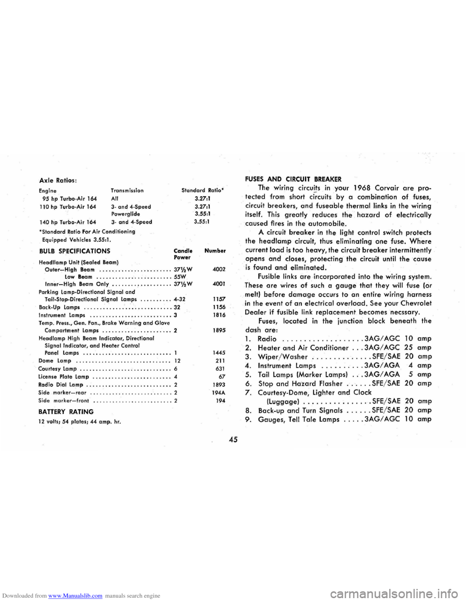
Downloaded from www.Manualslib.com manuals search engine Axle Ratios :
Engine
95 hp Turbo -Air 164
110 hp Turbo-Air 164
140 hp Turbo -Air 164 Transm
ission
All
3-and4-Speed Powerglide
3-and 4-Speed
'
StandardRatio For Air Cond itioning
Equipped Vehicles 3.55:1 .
BULB SPECIFICATIONS
Headllamp Unit (Sealed Beam)
Standard Ratio'
3.27:1
3 .27:1
3.55:1
3.55 :1
Candle Power Number
Outer~High Beam . .....•...•...•........ 37% W 4002 Low Beam .......... _ ....... _ .. _ .. SSW Inner-High Beam Only •....... , •.•. •.•... 37%W 4001
Park ing Lamp-Directional Signal and Tail-Stop -Directianal Signal Lamps ........ . . 4-32 1157
Back-Up Lamps
............................ 32 1156 Instrument Lamps ........ _ ...•••.....•....• 3 1816
Temp . Press., Gen. Fan., Brake Warning and Glove
Compartment Lamps ...........•... ..•..• . 2 1895
Headlamp High Beam
Indicator , Directional Signal Indicator, and Heater Control Panel Lamps ................•......•.•.. 1445
Dome Lamp ........................... ..• 12 211
Courtesy Lamp ............... . ; ....•..••... 6 631
License Plate Lamp ..............• •......... 4 67
Radio Dial Lamp .....................•..• " 2 1893 Side marker-rear .......................... 2 194A Side marker-front ......................... 2 194
BATTERY RATING
12 valls; 54 plates; 44 amp. hr.
45
FUSES AND CIRCUIT BREAKER
The wiring circuits in your 1968 Corvair are pro
tected from short ci~cuits by a combination of fuses,
circuit
breakers, and fuseable thermal links in the wiring
itself. This greatly reduces the hazard of electrically
caused fires in the automobile.
A circuit breaker in the light control switch protects
the headlamp circuit, thus eliminating one fuse. Where
current lo.ad is too heavy, the circuit breaker intermittently
opens and closes, protecting the circuit until the cause
is found and eliminated.
Fusible links are incorporated into the wiring system.
These
are wires of such a gauge that they will fuse (or
melt) before damage occurs to an entire wiring harness
in the event of an electrical overload. See your Chevrolet
Dealer if fusible link replacement becomes necssary.
Fuses,
located in the junction block beneath the
dash are:
1. Radio .
........ ...... .. , .3AG/AGC 10 amp
2. Heater and Air Conditioner ... 3AG/ AGC 25 amp
3. Wiper/Washer .............. SFE/SAE 20 amp
4 . Instrument lamps ......... . 3AG/ AGA 4 amp
5 . Tail lamps (Marker lamps) ... 3AG/ AGA 5 amp
6. Stop and Hazard Flasher ...... SFE/SAE 20 amp
7. Courtesy-Dome, lighter and Clock
(luggage) ................ SFE/SAE 20 amp
8. Back -up and Turn Signals ...... SFE/SAE 20 amp
9. Gauges, Tell Tale lamps ..... 3AG/ AGC 10 amp
Page 49 of 56
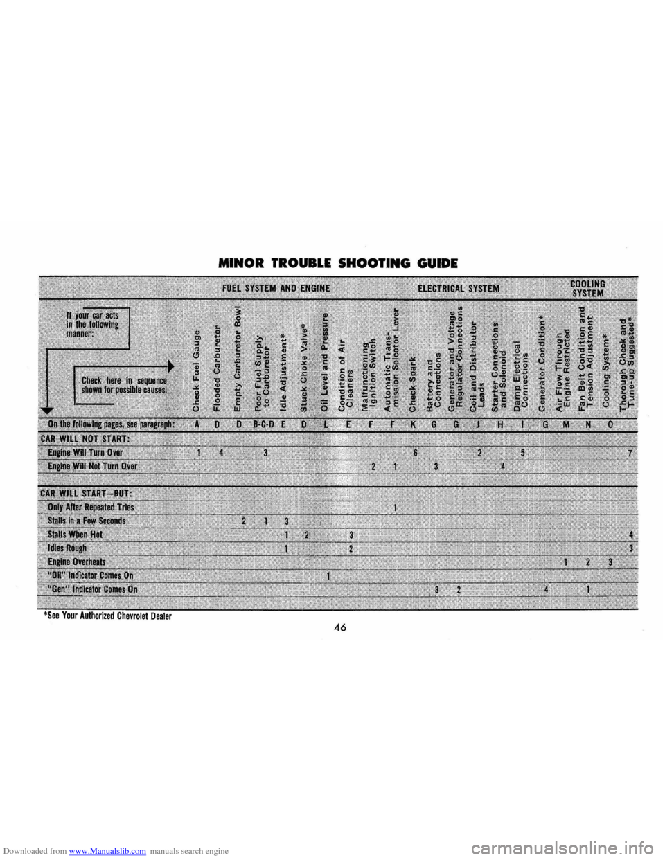
Downloaded from www.Manualslib.com manuals search engine MINOR TROUBLE SHOOTING GUIDE
46
Page 50 of 56
Downloaded from www.Manualslib.com manuals search engine MINOR TROUBLE SHOOTING PROCEDURES
The chart on the previous page, and the information on the pages
which follow, contains information designed to aid the average
driver to discover, and possibly correct, conditions resulting in minor
mechanical
difficulties in his car. The chart, designed to point out
possible solutions to
several of the most common automotive mal
functions
and point out a logical checking sequence, will lead step
by step to the most likely causes and corrective procedures. If, after
making the checks and adjustments suggested, the source of the
trouble
has not been found and corrected, it is strongly recom
mended
that an Authorized Chevrolet Dealer inspect the vehicle and
make whatever repairs or adjustments are necessary.
FUEL SYSTEM AND ENGINE
If the ignition switch will cause the engine to "turn over" or
"crank" but the car will not start, check Steps A through D below.
NOTE:
If continual "flooding" of the carburetor is evidenced by a
carburetor wet with fuel or black exhaust smoke, perform the
operation
suggested in paragraph 0 only .
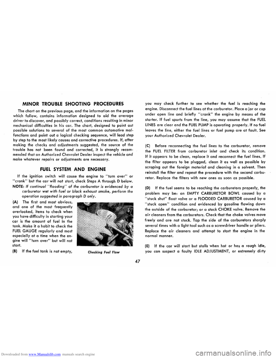
(A) The first and most obvious,
and one of the most frequently
overlooked, items to check when
you
have- difficulty in starting your
car is the amount of fuel in the
tank.
Make it a habit to check the
FUEL GAUGE regularly and most
especially
at a time when the en
gine will "turn over" but will not
start.
(8)
If the fuel tank is not empty, Checking Fuel Flow
47
you may check further to see whether the fuel is reaching the
engine. Disconnect the fuel lines
at the carburetor. Place a jar or cup
under open line and briefly "crank" the engine by means of the
starter. If fuel spurts from the line, you may assume that the FUEL
LINES are clear and the FUEL PUMP is operating properly. If no fuel
leaves the line, either the fuel lines
or fuel pump are at fault. See
your Authorized Chevrolet Dealer.
(C) Before reconnecting the fuel lines to the carburetor, remove
the
FUel FilTER from carburetor inlet and check its condition.
If it appears to be clean, replace it and reconnect the fuel lines. If
the filter appears to be plugged, clean it as well as possible by
scraping out the foreign material and cleaning in a solvent. Then
reinstall the filter
and repeat the procedure with the second carbu
retor. Replace the filters with new ones as soon as possible .
(0) If the fuel seems to be reaching the carburetors properly, the
problem may
be: an EMPTY CARBURETOR BOWL caused by a
"stuck shut" float valve or a flOODED CARBURETOR caused by a
"stuck open" condition and evidenced by gasoline flowing down
the outside
of the carburetor; or a stuck CHOKE valve. Remove the
air cleaners from the carburetors. Check that the choke valves move
freely and are not stuck. Tap the side of the carburetors sharply
several times with a light tool such as a screwdriver handle or pliers.
Replace the
air deaners and attempt to start the engine in the
normal manner.
(E) If the car will start but stalls when hot or has a rough idle,
you
can suspect a faulty IDLE ADJUSTMENT, or extremely dirty