CHEVROLET CORVAIR 1986 2.G User Guide
Manufacturer: CHEVROLET, Model Year: 1986, Model line: CORVAIR, Model: CHEVROLET CORVAIR 1986 2.GPages: 56, PDF Size: 22.23 MB
Page 11 of 56
Downloaded from www.Manualslib.com manuals search engine STARTING THE ENGINE
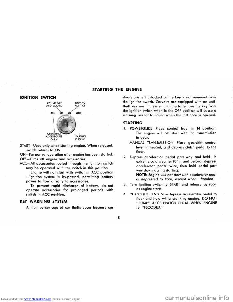
IGNITION SWITCH
OPERA ACCESSORIES ONLY DRIVING STARTING ENGINE
START-Used only when
starting engine. When released,
switch returns to ON.
ON-For normal operation after engine has been started.
OFF-Turns off engine and accessories.
ACC-AII accessories routed through the ignition switch
may
be operated with the switch in this position.
Engine will not
start with switch in ACC position
-ignition system is by-passed, permitting battery
power to flow directly to accessories.
To prevent rapid discharge of battery, do not
operate accessories for prolonged periods with
switch
in ACC position.
KEY WARNING SYSTEM
A high percentage of car thefts occur because car
8
doors are left unlocked or the key is not removed from
the ignition switch. Corvairs
are equipped with an anti
theft key warning system. Failure
to remove the key from
the ignition switch when
in the OFF position will cause a
warning
buzzer to sound when the left door is opened.
STARTING
1. POWERGLIDE-Place control lever in N position.
The
engine will not start with the transmission
in gear.
MANUAL TRANSMISSION-Place gearshift control
lever in neutral, and depress clutch pedal to the
floor.
2. Depress accelerator pedal part way and hold. In
extreme cold weather (O°F. and below), depress
accelerator pedal twice, then hold pedal part
way down during starting .
NOTE: Engine will not start with accelerator ped
al depressed to floor, except when "flooded."
3. Turn ignition switch to START and release as soon
as
engine starts .
4. "FLOODED" ENGINE-Depress accelerator pedal to
floor
and hold while cranking engine. DO NOT
"PUMP"
ACCELERATOR PEDAL WHEN ENGINE
IS "FLOODED."
Page 12 of 56
Downloaded from www.Manualslib.com manuals search engine WARM-UP
Never race engine or drive at high speeds until
engine has
had a chance to warm up. Driving with
moderate accelerator pedal application will prevent
stalling
and hesitation, especially during cold weather.
Failure
to allow sufficient warm up time can cause un
necessary wear to engine, axle or transmission parts
because of inadequate lubrication.
DRIVING WITH THE
MANUAL TRANSMISSIONS
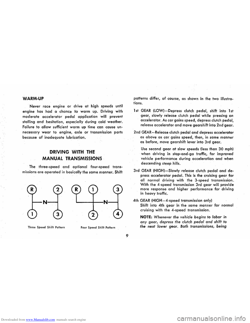
The three-speed and optional four-speed trans
missions are operated in basically the same manner. Shift
N "'-----+--N
Three Speed Shift Pallern Four Speed Shift Pattern
9
patterns differ, of course, as shown in the two illustra
tions.
1 st
GEAR (LOW)-Depress clutch pedal, shift into 1 st
gear, slowly release clutch pedal while pressing on
accelerator.
As car gains speed, depress clutch pedal,
release accelerator and move gearshift into 2nd gear.
2nd GEAR-Release clutch pedaI and depress accelerator
as above as car gains speed, then, in same manner
as before, move gearshift lever into 3rd gear.
Use second gear at slow speeds (less than 30 mph)
when driving
in stop-and-go traffic, for improved
vehicle performance during acceleration
and when
descending steep hills.
3rd
GEAR (HIGH)-Slowly release clutch pedal and de
press accelerator pedal. This is the cruising gear for
all normal driving with the
3-speed transmission.
With the
4-speed transmission 3rd gear will provide
more response
and higher performance for driving
in heavy traffic.
4th
GEAR (HIGH-4-speed transmission only)
Shift into 4th
gear in the same manner for normal
cruising with the
4-speed transmission.
NOTE: Whenever the vehicle begins to labor in
any gear, depress the clutch pedal and shift to
the next lower
gear. Both transmissions, being
Page 13 of 56
Downloaded from www.Manualslib.com manuals search engine fully synchronized, may be downshifted into first
gear at any speed below 20 mph.
TO STOP-Release the accelerator and depress the
brake pedal. As car slows down, depress the clutch
pedal and move the gearshift lever into neutral.
NEUTRAL-For use when starting or idling engine.
REVERSE-Operate as for 1 st gear but always at a
slow speed.
CAUTION: When parking or leaving the car unattended,
even for a few minutes, remove the ignition key, place
the selector lever in first gear or reverse if manual trans
mission, and fully apply the parking brake.
DRIVING WITH THE POWERGLIDE TRANSMISSION
The optional Powerglide transmission is a completely
automatic transmission which replaces the standard clutch
and transmission. After starting the engine with the se
lector lever
in N (neutral) position, merely select the
range desired and depress the accelerator. The Power
glide
transmission will do the rest.
Automatic transmission shift
quadrants of all GM
cars continue the uniform sequence of selector positions.
This particularly benefits multicar families and those who
occasionally drive other cars. Shift indicators are ar
ranged as follows: "Reverse", "Neutral" and the forward
driving
ranges. All automatic transmissions are equipped
with a starter interlock system designed to permit start
ing the engine only when the transmission selector is in
the "Neutral" position. For additional engine braking
effect,
as sometimes needed in mountainous driving,
place the transmission in an intermediate or low range.
10
The dash-mounted driving range selector is equipped
with mechanical stops to prevent unintentional shifting
into reverse
and low ranges. Move lever to the left, to
override stop,
and continue shift for selection of reverse
or low ranges.
With
lever in 0 position the transmission starts in
automatic low gear and will shift to cruising gear at
some point between approximately 12 and 50 mph,
depending on the accelerator position. Thus, a slow start
with a steady, gradual increase of pressure on the accel
erator pedal will enable the transmission to shift into the
more economical cruising gear in the shortest possible
time. Hard acceleration for fast starts will cause the trans
mission to remain in low gear for a considerably longer
period.
When driving at speeds below 45 mph, the transmis-
Page 14 of 56
Downloaded from www.Manualslib.com manuals search engine sion may be shifted into low range for extra acceleration
for passing by depressing the
accelerator pedal fully. The
transmission
will automatically shift back into cruising
gear when the accelerator pedal is momentarily released.
CAUTION: It is important that the parking brake be fully engaged, in addition to removing the ignition key,
when your Corvair is parked or otherwise left unattended. The automatic transmission does not hold the car
regardless
of the position of the selector lever.
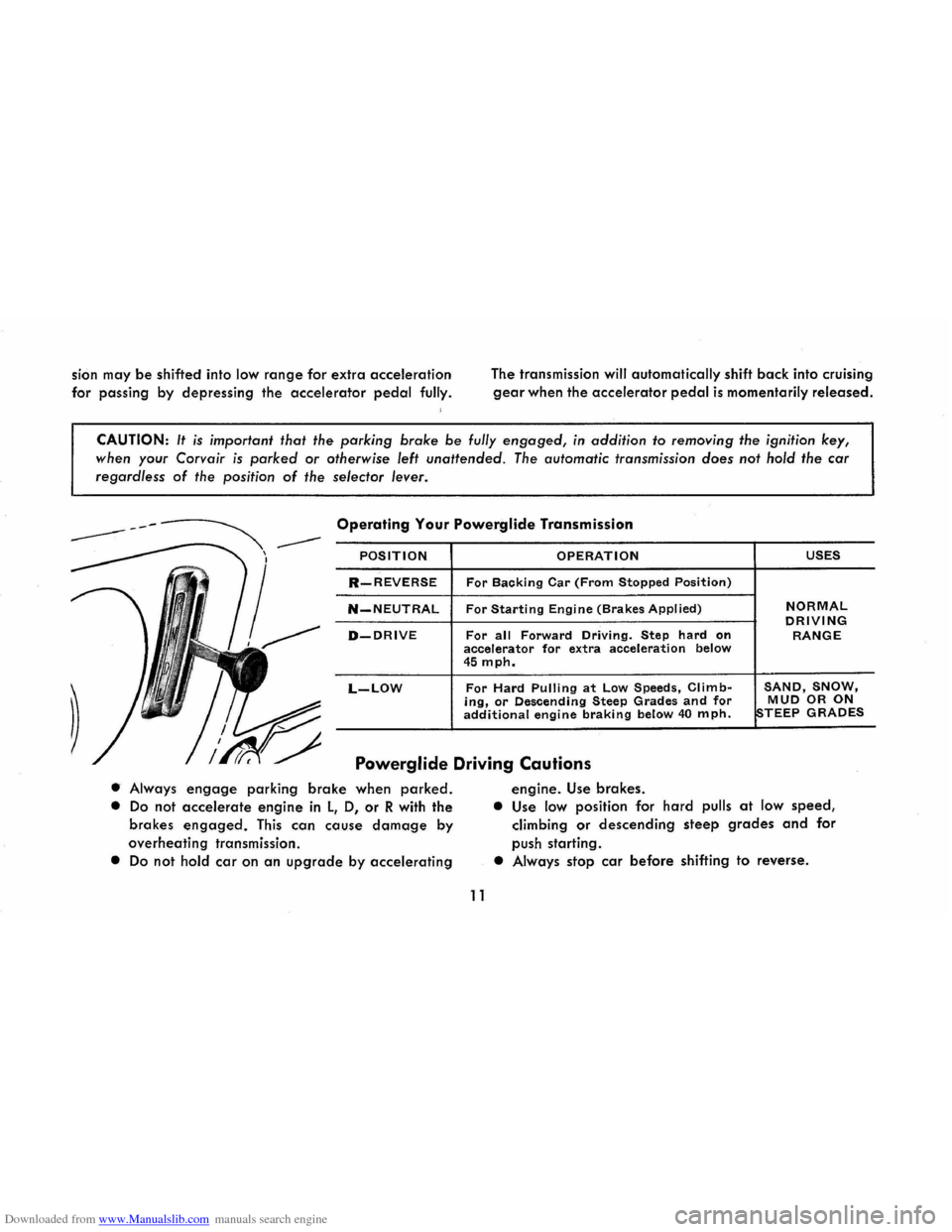
Operating Your Powerglide Transmission
POSITION OPERATION USES
R-REVERSE For Backing Car (From Stopped Position)
N-NEUTRAL For Starting Engine (Brakes Applied) NORMAL DRIVING D-DRIVE For all Forward Driving. Step hard on RANGE accelerator for extra acceleration below 45 mph.
L-LOW For Hard Pulling at Low Speeds, Climb-SAND, SNOW, ing, or Descending Steep Grades and for MUD OR ON additional engine braking below 40 mph. STEEP GRADES
Powerglide Driving Cautions
• Always engage parking brake when parked.
• Do not accelerate engine in l, 0, or R with the
brakes
engaged. This can cause damage by
overheating transmission.
• Do not hold car on an upgrade by accelerating
11
engine. Use brakes.
• Use low position for hard pulls at low speed,
climbing or descending steep grades and for
push starting.
• Always stop car before shifting to reverse.
Page 15 of 56
Downloaded from www.Manualslib.com manuals search engine TRANSMISSION OPERATING TIPS
EMERGENCY STARTING
Your Corvair may be started in an emergency by
pushing. When being pushed to start the engine, turn
off all unnecessary electrical loads, turn the ignition to "ON", and (if manual transmission) depress the
clutch and place the shift lever in high gear or, (if
powerglide) move selector lever to NEUTRAL position.
Release the clutch when car speed reaches 10 to 15 miles per hour (manual transmission); move the selector
lever to LOW position when car speed reaches 20 to
25 miles per hour (powerglidel. Bumpers and other
parts contacted by the pushing vehicle should be pro
tected from damage while pushing. Never tow the car
to start.
TOWING
Normally your Corvair may be towed with all four
wheels on the ground for distances up to 50 miles at
12
speeds of less than 35 mph. The engine should be off
ahd the transmission in neutral.
However, the drive wheels (rear wheels) must be
raised off the ground or the drive shaft disconnected
when the transmission
is not operating properly or when
a speed
of 35 mph or distance of 50 miles will be exceeded.
CAUTION: If car is towed on its front wheels only, the
steering wheel must
be secured with the wheels in a
straight ahead position .
ROCKING CAR
If it becomes necessary to rock the car to free it
from sand, mud or snow, move the selector lever from "D" to "R" (automatic transmission) or the shift lever
from forward to reverse (manual transmission) in a
repeat pattern while simultaneously applying moderate
pressure to the accelerator. Do not race engine. Avoid
spinning wheels when trying to free the car.
Page 16 of 56
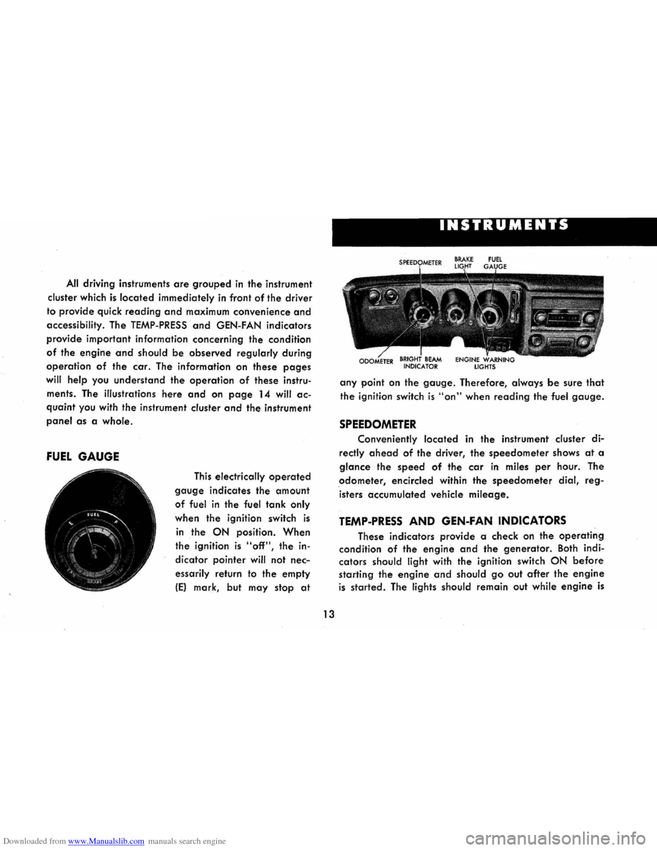
Downloaded from www.Manualslib.com manuals search engine All driving instruments are grouped in the instrument
cluster which
is located immediately in front of the driver
to provide quick
reading and maximum convenience and
accessibility. The TEMP-PRESS and GEN-FAN indicators
provide important information concerning the condition
of the engine and should be observed regularly during
operation of the car. The information on these pages
will help you understand the operation of these instru
ments . The illustrations
here and on page 14 will ac
quaint you with the instrument cluster and the instrument
panel as a whole.
FUEL GAUGE
This electrically operated
gauge indicates the amount
of fuel in the fuel tank only
when the ignition switch is
in the ON position. When
the ignition is "off", the in
dicator pointer
will not nec
essarily return to the empty
IE) mark, but may stop at
I
13
INSTRUMENTS
any point on the gauge. Therefore, always be sure that
the ignition switch is "on" when reading the fuel gauge.
SPEEDOMETER
Conveniently located in the instrument cluster di
rectly ahead of the driver, the speedometer shows at a
glance the speed of the car in miles per hour. The
odometer, encircled within the speedometer dial, reg
isters accumulated vehicle
mileage.
TEMP-PRESS AND GEN-FAN INDICATORS
These indicators provide a check on the operating
condition of the engine and the generator. Both indi
cators
should light with the ignition switch ON before
starting the engine and should go out after the engine
is started. The lights should remain out while engine is
Page 17 of 56
Downloaded from www.Manualslib.com manuals search engine operating, except the GEN-FAN indicator rna)' flicker
when
engine is idling.
CAUTION: If either of these indicators light
while .
car is being. -driYen, immediately follow the
procedure outlined .vnder "EMERGENCY OPER
ATING INSTRUCTIONS," so car may be driyen
to the nearest service facility.
BRAKE SYSTEM WARNING LIGHT
This dual purpose indicator light operates as
follows:
With parking brake applied the red light will light
when
the ignition switch is turned on.
As a dual service brake system warning, the red
light will come on when the brake pedal is depressed
if low pressure has developed in either the front or
rear brake system. Have your authorized Chevrolet
dealer locate and correct the trouble immediately.
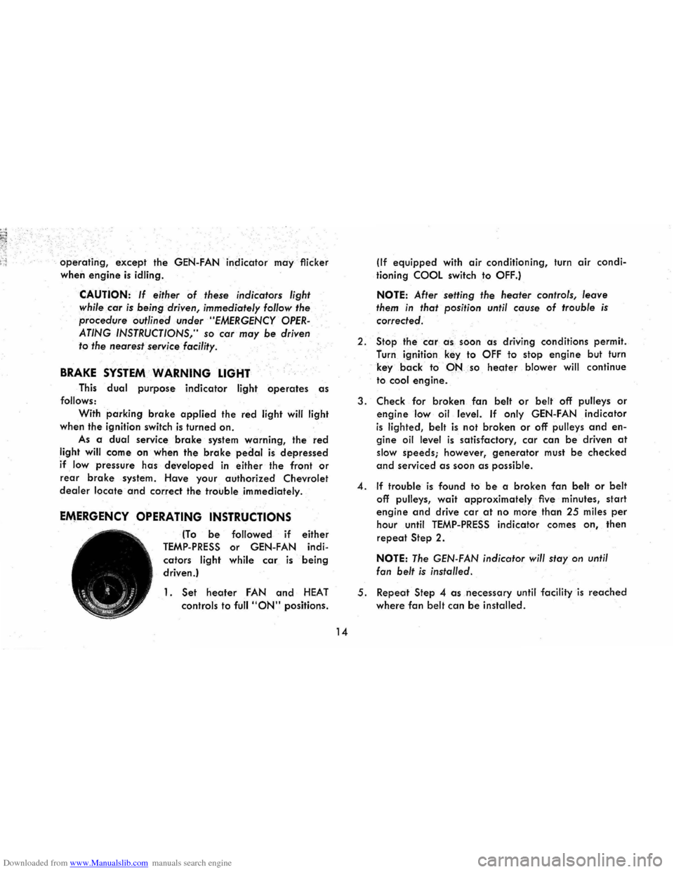
EMERGENCY OPERATING INSTRUCTIONS
(To be followed if either
TEMP-PRESS or GEN-FAN indi
cators
light while car is being
driven.)
1. Set heoter FAN and HEAT
controls to full "ON" positions.
14
(If equipped with air conditioning, turn air condi
tioning
COOL switch to OFF.)
NOTE: After setting the heater controls, leave
them in that position until cause of trouble is
corrected.
2.
Stop the car a -s , soon as driving conditions permit.
furn ignition
key to OFF to stop engine but turn
key
back to·-PNso heoter blower will continue
to
cool engine.
3. Check for broken fan belt or belt off pulleys or
engine low oil level. If only GEN-FAN indicator
is lighted, belt is not broken or off pulleys and en
gine oil level is satisfactory, car can be driven at
slow speeds; however, generator must be checked
and serviced as soon as possible.
4. If trouble is found to be a broken fan belt or belt
off pulleys, wait approximately five minutes, start
engine and drive car at no more than 25 miles per
hour until TEMP-PRESS indicator comes on, then
repeat Step 2.
NOTE: The GEN-FAN indicator will stay on until
fan
belt is installed.
5. Repeat Step 4 as necessary until facility is reached
where fan belt can be installed.
Page 18 of 56
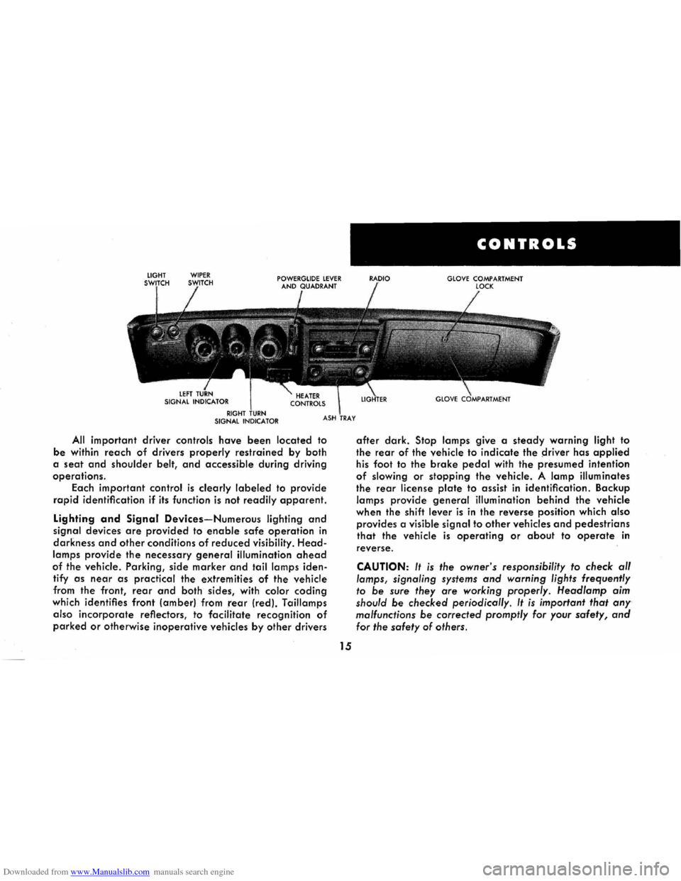
Downloaded from www.Manualslib.com manuals search engine All important driver controls have been located to
be within reach of drivers properly restrained by both
a
seat and shoulder belt, and accessible during driving
operations.
Each important
control is clearly labeled to provide
rapid identification if its function is not readily apparent.
Lighting and Signal Devices-Numerous lighting and
signal devices are provided to enable safe operation in
darkness and other conditions of reduced visibility. Head
lamps provide the necessary general illumination ahead
of the vehicle. Parking, side marker and tail lamps iden
tify
as near as practical the extremities of the vehicle
from the front,
rear and both sides, with color coding
which identifies front (amber) from rear (red). Taillamps
also
incorporate reflectors, to facilitate recognition of
parked or otherwise inoperative vehicles by other drivers
15
CONTROLS
GLOVE COMPARTMENT
after dark. Stop lamps give a steady warning light to
the rear of the vehicle to indicate the ~river has applied
his foot to the brake pedal with the presumed intention
of slowing or stopping the vehicle. A lamp illuminates
the rear license plate to assist in identification. Backup
lamps provide general illumination behind the vehicle
when the shift
lever is in the reverse position which also
provides a visible signal to other vehicles and pedestrians
that the vehicle is operating or about to operate in
reverse.
CAUTION: It is the owner's responsibility to check al/
lamps, signaling systems and warning lights frequently
to be sure they are working properly. Head/amp aim
should
be checked periodicol/y. It is important that any
malfunctions be corrected promptly for your safety, and
for the safety of others.
Page 19 of 56
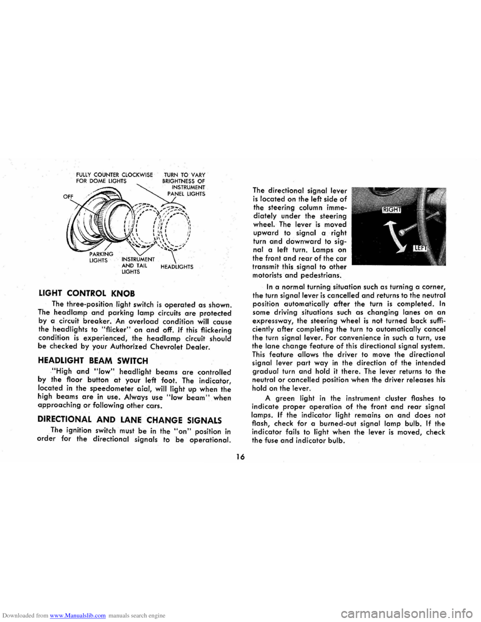
Downloaded from www.Manualslib.com manuals search engine FULLY COUNTER CLOCKWISE FOR DOME LIGHTS
LIGHTS INSTRUMENT
AND TAIL
LIGHTS
LIGHT CONTROL KNOB
TURN TO VARY BRIGHTNESS OF INSTRUMENT
PANEL LIGHTS
HEADLIGHTS
The three-position light switch is operated as shown.
The
head lamp and parking lamp circuits are protected
by a circuit breaker. An overload condition will cause
the headlights to "flicker" on and off. If this flickering
condition
is experienced, the headlamp circuit should
be checked by your Authorized Chevrolet Dealer.
HEADLIGHT BEAM SWITCH
,"High and "low" headlight beams are controlled
by
the floor button at your left foot. The indicator,
located
in the speedometer aial, will light up when the
high beams are in use . Always use "Iow beam" when approaching or following other cars.
DIRECTIONAL AND LANE CHANGE SIGNALS
The ignition switch must be in the "on" position in
order for the directional signals to be operational.
16
The directional signal lever
is located on the left side of
the steering column imme
diately
under the steering
wheel. The lever is moved
upward to signal a right
turn
and downward to sig
nal a left turn. Lamps on
the front and rear of the car
transmit this signal to other
motorists and pedestrians.
In a normal turning situation such as turning a corner,
the turn signal lever is cancelled and returns to the neutral
position automatically
after the turn is completed. In
some driving situations such as changing lanes on an
expressway, the steering wheel is not turned back suffi
ciently after completing the turn to automatically cancel
the turn signal lever. For convenience in such a turn, use
the lane change feature of this directional signal system.
This feature allows the driver to move the directional
signal lever
part way in the direction of the intended
gradual turn and hold it there. The lever returns to the
neutral or cancelled position when the driver releases his
hold on the lever.
A green light in the instrument cluster flashes to
indicate
proper operation of the front and rear signal
lamps.
If the indicator light remains on and does not
flash, check for a burned-out
signal lamp bulb. If the
indicator fails to light when the lever is moved, check
the fuse and indicator bulb.
Page 20 of 56
Downloaded from www.Manualslib.com manuals search engine If the system is not functioning properly, a legal hand
signal should be given, since failure to indicate a turn
is considered a moving traffic violation in many states.
Always signal for a turn
at a reasonable distance before actu 'ally making it.
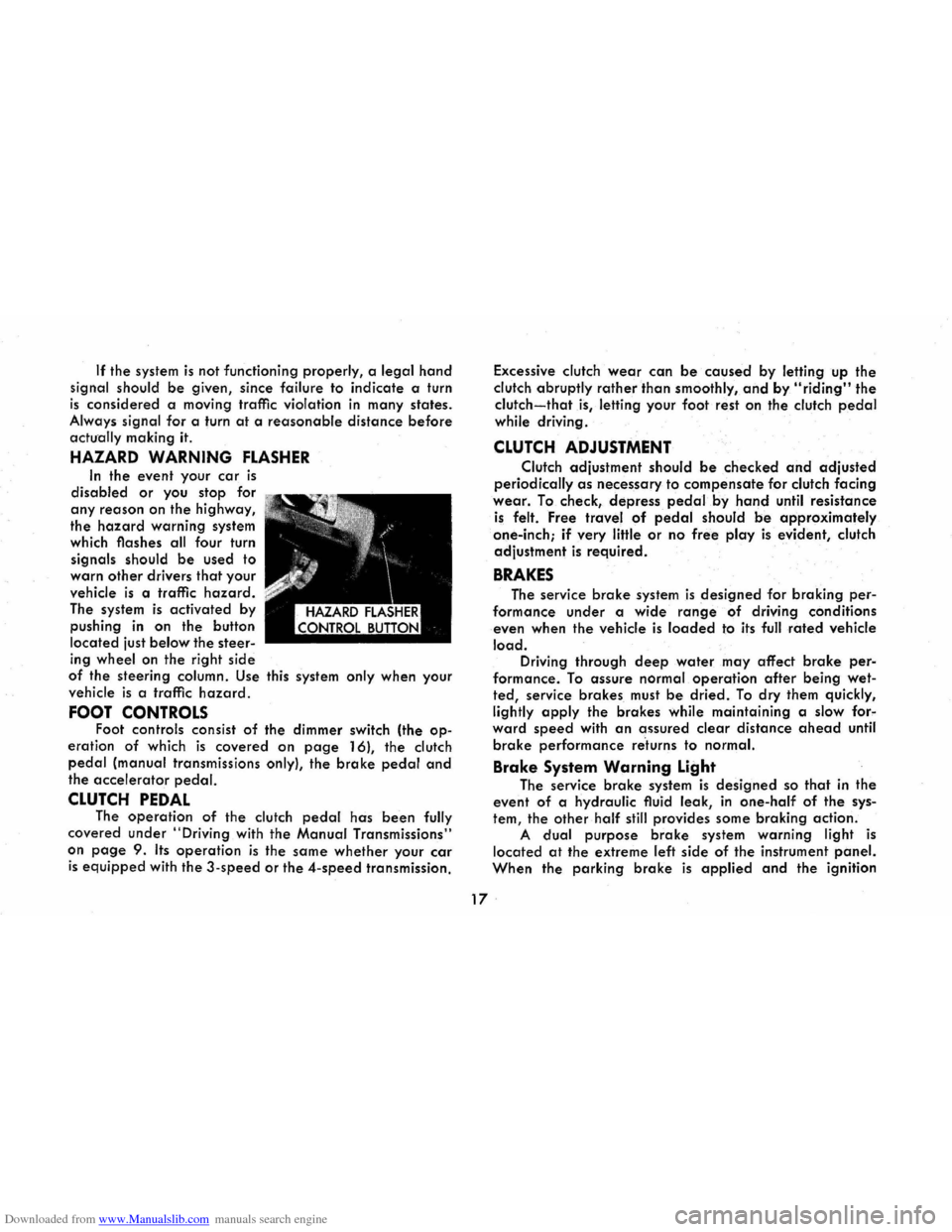
HAZARD WARNING FLASHER
In the event your car is
disabled or you stop for
any reason on the highway,
the
hazard warning system
which flashes all four turn
signals should
be used to
warn
other drivers that your
vehicle
is a traffic hazard.
The system is activated by
pushing
in on the button
located just
below the steer
ing wheel on the right side
of the steering column. Use this system only when your
vehicle
is a traffic hazard.
FOOT CONTROLS Foot controls consist of the dimmer switch (the op
eration of which is covered on page 16), the clutch
pedal (manual transmissions only), the brake pedal and
the accelerator pedal.
CLUTCH PEDAL The operation of the clutch pedal has been fully
covered under
"Driving with the Manual Transmissions"
on
page 9. Its operation is the same whether your car
is equipped with the 3-speed or the 4-speed transmission. Excessive
clutch
wear can be caused by letting up the
clutch abruptly
rather than smoothly, and by "riding" the
clutch-that is, letting your foot rest on the clutch pedal
while driving .
CLUTCH ADJUSTMENT
Clutch adjustment should be checked and adjusted
periodically as necessary to compensate for clutch facing
wear. To check, depress pedal.by hand until resistance
is felt. Free travel of pedal should be approximately
one-inch;
if very little or no free play is evident, clutch
adjustment
is required.
BRAKES
The service brake system is designed for braking per
formance under a wide range of driving conditions
even when the vehicle
is loaded to its full rated vehicle
load. Driving through deep water may affect brake per
formance. To assure normal operation after being wet
ted, service brakes must be dried. To dry them quickly,
lightly
apply the brakes while maintaining a slow for"
ward speed with an assured clear distance ahead until
brake performance re'turns to normal.
Brake System Warning Light
The service brake system is designed so that in the
event of a hydraulic fluid leak,
in one-half of the sys
tem, the other half still provides some braking action.
A dual purpose brake system warning light is
located at the extreme left side of the instrument panel.
When the parking brake is applied and the ignition
17 .