battery CHEVROLET CORVAIR 1986 2.G Owners Manual
[x] Cancel search | Manufacturer: CHEVROLET, Model Year: 1986, Model line: CORVAIR, Model: CHEVROLET CORVAIR 1986 2.GPages: 56, PDF Size: 22.23 MB
Page 11 of 56
Downloaded from www.Manualslib.com manuals search engine STARTING THE ENGINE
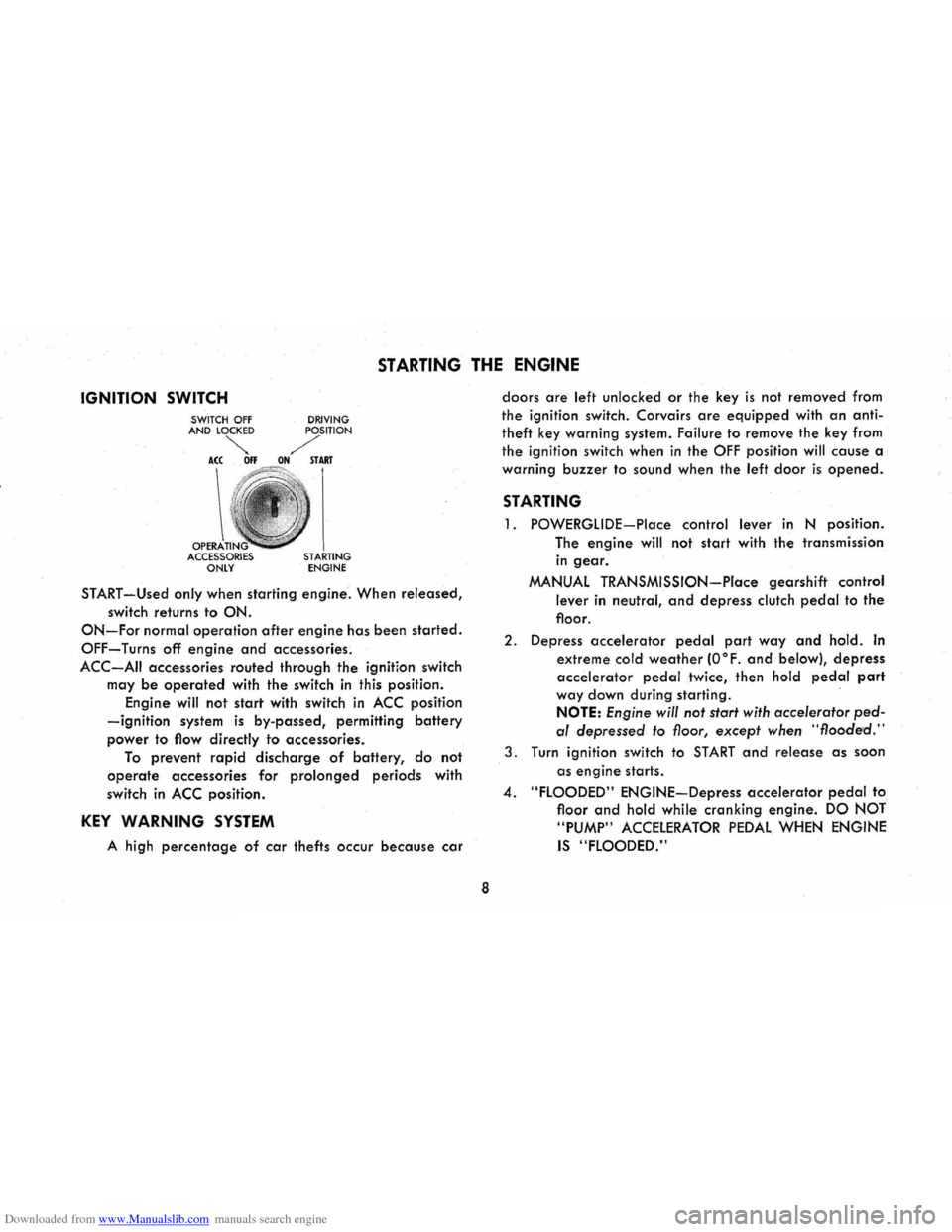
IGNITION SWITCH
OPERA ACCESSORIES ONLY DRIVING STARTING ENGINE
START-Used only when
starting engine. When released,
switch returns to ON.
ON-For normal operation after engine has been started.
OFF-Turns off engine and accessories.
ACC-AII accessories routed through the ignition switch
may
be operated with the switch in this position.
Engine will not
start with switch in ACC position
-ignition system is by-passed, permitting battery
power to flow directly to accessories.
To prevent rapid discharge of battery, do not
operate accessories for prolonged periods with
switch
in ACC position.
KEY WARNING SYSTEM
A high percentage of car thefts occur because car
8
doors are left unlocked or the key is not removed from
the ignition switch. Corvairs
are equipped with an anti
theft key warning system. Failure
to remove the key from
the ignition switch when
in the OFF position will cause a
warning
buzzer to sound when the left door is opened.
STARTING
1. POWERGLIDE-Place control lever in N position.
The
engine will not start with the transmission
in gear.
MANUAL TRANSMISSION-Place gearshift control
lever in neutral, and depress clutch pedal to the
floor.
2. Depress accelerator pedal part way and hold. In
extreme cold weather (O°F. and below), depress
accelerator pedal twice, then hold pedal part
way down during starting .
NOTE: Engine will not start with accelerator ped
al depressed to floor, except when "flooded."
3. Turn ignition switch to START and release as soon
as
engine starts .
4. "FLOODED" ENGINE-Depress accelerator pedal to
floor
and hold while cranking engine. DO NOT
"PUMP"
ACCELERATOR PEDAL WHEN ENGINE
IS "FLOODED."
Page 45 of 56
Downloaded from www.Manualslib.com manuals search engine AIR CLEANER
CAUTION: In addition to its function of filtering air
drawn into
the engine through the carburetor, the air
cleaner also acts as
a flame arrester in the event the
engine backfires. Because backfiring
may cause fire in
the engine compartment, the air cleaner should be in
stalled at all times unless its removal is necessary for
repair or maintenance services.
Paper Element Type
The oil-wetted paper element is a long-life efficient air
cleaner and should not require replacement before
24,000 miles except under extreme adverse condi
tions .
Inspect air cleaner at 12,000 miles for dust leaks,
holes
or other damage, replace if necessary . If
condition is satisfactory, rotate element 1800 from
originally installed position. Replace
at 24,000 miles.
Under extreme
adverse conditions inspect every 6,000 miles.
Oil Bath Type
Every 12,000 miles-Inspect and clean if necessary.
Refill with SAE 50 engine oil when lowest anticipated
temperature is above freezing; use SAE 20 if below
freezing.
BATTERY (ENERGIZER)
Every 6,000 miles-Clean and oil battery terminals and
oil felt washer. Check fluid level frequently. Keep
filled with distilled water to level of split ring in
42
vent tube. The electrolyte level indicator in the cap
of one cell will glow if the fluid level is low. In this
case each cell should be checked.
CAUTION: Since normal battery or Energizer
chemical action generates hydrogen gas which
is highly explosive when mixed with air, never
expose the battery to an open flame or electric
spark. Also, avoid getting battery fluid, which
is a sulfuric acid solution, on skin, on clothing
or other fabrics, or on painted surfaces . Eye
protection should
be worn while working on the
battery for
any reason.
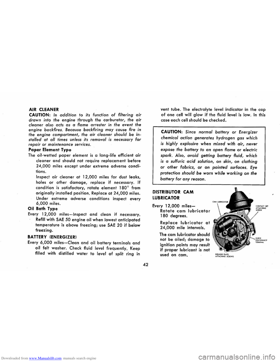
DISTRIBUTOR CAM
LUBRICATOR
Every 12,000 miles
Rotate cam lubricator
180 degrees.
Replace lubricator at
24,000 mile intervals.
The cam lubricator should
not
be oiled; damage to
ignition points may result
if
proper lubricant is not
used
on cam. 8RE,AKEIt PlATE ATTACHtNG SCREWS
Page 48 of 56
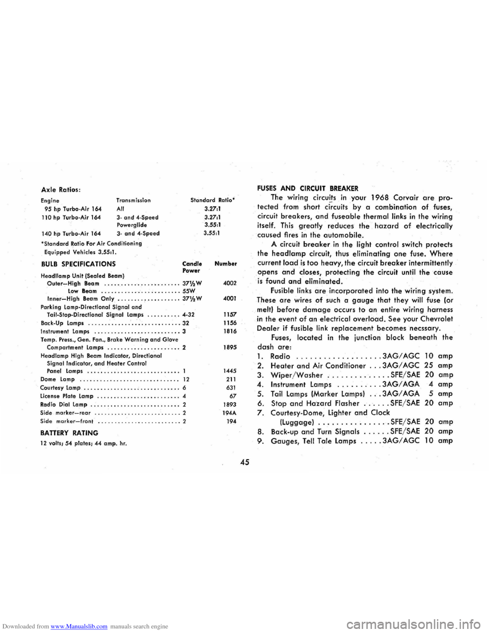
Downloaded from www.Manualslib.com manuals search engine Axle Ratios :
Engine
95 hp Turbo -Air 164
110 hp Turbo-Air 164
140 hp Turbo -Air 164 Transm
ission
All
3-and4-Speed Powerglide
3-and 4-Speed
'
StandardRatio For Air Cond itioning
Equipped Vehicles 3.55:1 .
BULB SPECIFICATIONS
Headllamp Unit (Sealed Beam)
Standard Ratio'
3.27:1
3 .27:1
3.55:1
3.55 :1
Candle Power Number
Outer~High Beam . .....•...•...•........ 37% W 4002 Low Beam .......... _ ....... _ .. _ .. SSW Inner-High Beam Only •....... , •.•. •.•... 37%W 4001
Park ing Lamp-Directional Signal and Tail-Stop -Directianal Signal Lamps ........ . . 4-32 1157
Back-Up Lamps
............................ 32 1156 Instrument Lamps ........ _ ...•••.....•....• 3 1816
Temp . Press., Gen. Fan., Brake Warning and Glove
Compartment Lamps ...........•... ..•..• . 2 1895
Headlamp High Beam
Indicator , Directional Signal Indicator, and Heater Control Panel Lamps ................•......•.•.. 1445
Dome Lamp ........................... ..• 12 211
Courtesy Lamp ............... . ; ....•..••... 6 631
License Plate Lamp ..............• •......... 4 67
Radio Dial Lamp .....................•..• " 2 1893 Side marker-rear .......................... 2 194A Side marker-front ......................... 2 194
BATTERY RATING
12 valls; 54 plates; 44 amp. hr.
45
FUSES AND CIRCUIT BREAKER
The wiring circuits in your 1968 Corvair are pro
tected from short ci~cuits by a combination of fuses,
circuit
breakers, and fuseable thermal links in the wiring
itself. This greatly reduces the hazard of electrically
caused fires in the automobile.
A circuit breaker in the light control switch protects
the headlamp circuit, thus eliminating one fuse. Where
current lo.ad is too heavy, the circuit breaker intermittently
opens and closes, protecting the circuit until the cause
is found and eliminated.
Fusible links are incorporated into the wiring system.
These
are wires of such a gauge that they will fuse (or
melt) before damage occurs to an entire wiring harness
in the event of an electrical overload. See your Chevrolet
Dealer if fusible link replacement becomes necssary.
Fuses,
located in the junction block beneath the
dash are:
1. Radio .
........ ...... .. , .3AG/AGC 10 amp
2. Heater and Air Conditioner ... 3AG/ AGC 25 amp
3. Wiper/Washer .............. SFE/SAE 20 amp
4 . Instrument lamps ......... . 3AG/ AGA 4 amp
5 . Tail lamps (Marker lamps) ... 3AG/ AGA 5 amp
6. Stop and Hazard Flasher ...... SFE/SAE 20 amp
7. Courtesy-Dome, lighter and Clock
(luggage) ................ SFE/SAE 20 amp
8. Back -up and Turn Signals ...... SFE/SAE 20 amp
9. Gauges, Tell Tale lamps ..... 3AG/ AGC 10 amp
Page 51 of 56
Downloaded from www.Manualslib.com manuals search engine and blocked AIR CLEANER ELEMENTS. Replace the air cleaner ele
ments
if necessary. Idle adjustment should be performed by your
Chevrolet Dealer.
If the above Fuel System checks and the checks suggested under
the Electrical System following do not correct the malfunction, it is
recommended that you turn to your Authorized Chevrolet Dealer
for further checks, adjustments
or repairs.
ELECTRICAL SYSTEM
If, when the ignition key is turned to START, the engine will not
turn over, you have
good reason to suspect electrical trouble.
(F) When there is no response at all to attempts to start the car,
check the obvious-your AUTOMATIC TRANSMISSION SELECTOR
LEVER must be in neutral position before the engine can be started.
Turning the IGNITION SWITCH rapidly back and forth several
times
will sometimes correct a poor internal switch contact.
(G) The BATTERY may be discharged. If so, lights will be dim and
the horn will have a poor tone if it will blow at all.
Usually
a garage recharge will be necessary to return the battery
to operotion. Occasionally, however, a long drive will recharge
the battery.
NOTE:
If the battery is determined to be dead, and for no apparent
reason, have
your Authorized Chevrolet Dealer check the
battery, the GENERATOR and the
VOLTAGE REGULATOR.
GENERATOR trouble should already have been indicated
by
the indicator on the instrument panel. Never remove generator
"BAT" lead without first disconnecting battery ground cable.
48
POOR BATTERY CONNECTIONS may be suspected if the car has operated properly a short time before and now not even the horn
will operate. Check both ends of both battery cables. If the con
nections are corroded, a car may sometimes be restored to operation by removing all cable ends, scraping all contacting surfaces
clean with a pen knife, and reassembling. If the cables are broken,
they must be replaced. The power supply should now be restored
unless the battery is dead.
(H) If, however, the lights and horn work properly but the starter will still not turn over, check the STARTER connections. A "click" from the starter solenoid indicates that the wiring to the starter is properly installed. If the wiring seems to be clean and tightly installed, the trouble is probably in the starter itself and should be referred to your Authorized Chevrolet Dealer.
When the engine will "turn over" but will not start, the following
items may be checked along with Fuel System Checks listed previously.
(I) With a clean dry cloth wipe the ceramic portions of the spark plugs dry. In particularly damp or rainy weather dampness may be the cause of not sta rting, especially when the engine is cold.
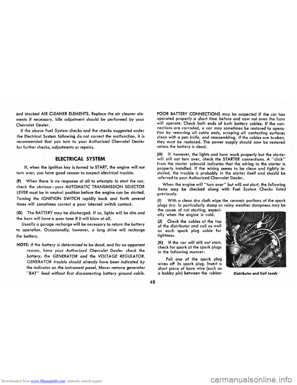
(J) Check the cables at the top of the distributor and coil as well as each spark plug cable for
tightness.
(K) If the car will still not start, check for spark at the spark plugs in the following manner:
Pull one of the spark plug
wires off its spark plug. Insert a
short piece of bare wire (such as a bobby pin) between the rubber Distributor and Coil Leads
Page 55 of 56
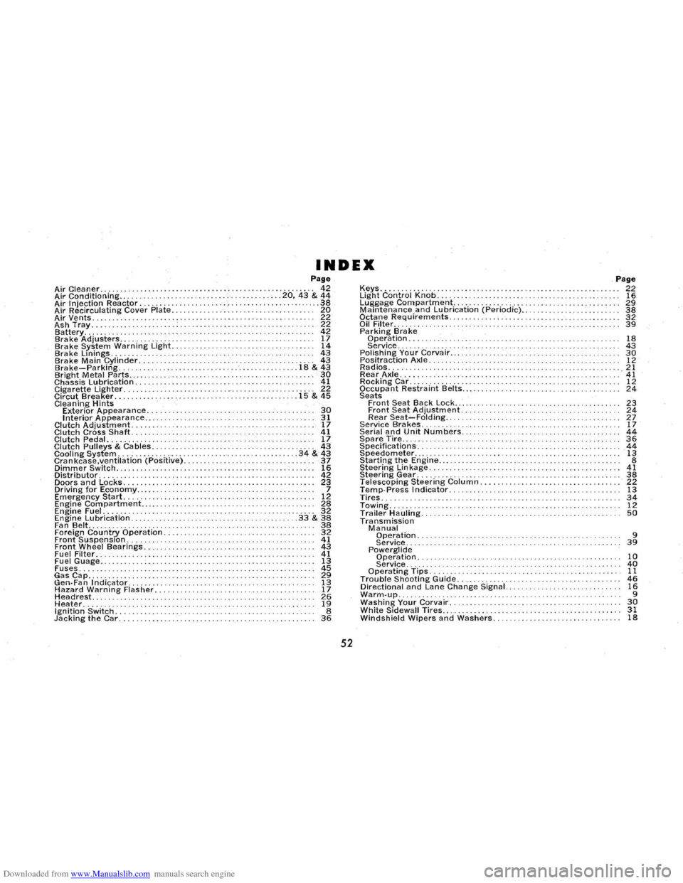
Downloaded from www.Manualslib.com manuals search engine INDEX Page Air Cleaner. . . . . . . . . .. , .. . . . . . . .. . . . . . . . . . . .......... 42 Air Conditioning.. ............ ... .... .• . . .20,43 & 44 Air Injection Reactor......... ........... . ... ... 38 Air Recirculating Cover Plate. . . . . . . . . . . .• . . . . .. . . . .. . . 20 Air Vents. . . . . . . . . . . . . . . . . . . . . . . 22 Ash Tray. ........ .. ... 22 Battery........... ............ ....•...•................. 42 Brake Adjusters...................... .. .. ... ............. 17 Brake System Warning Light. . ................. 14 Brake Lmings. . ....... ....... ........ ............... 43 Brake Main Cylinder.. ........... . ...... 43 Brake-Parking. . ............ .......... . .. 18 & 43 Bright Metal Parts..... .. ..................... '. 30 Chassis Lubrication. . . . . . . . . . . . . . 41 Cigarette Lighter. . . .. .... ... .. . . . .. .. " 22 Circut Brea ker. . . . . . ................. .. .............. 15 & 45 Cleaning Hints Exterior Appearance........ .... .... . ............ . 30 Interior Appearance.. ............... . ............. ........ 31 Clutch Adjustment......... 17 Clutch Cross Shaft. . . .. . . . . . . . ... .. . . 41 Clutch Pedal.. .. . .. .. .. .. . . .. .. . .. .. . 17 Clutch Pulleys & Cables..................... . 43 Cooling System. . . . . . . . . . . . . . . . . . ........ ....... 34 & 43 Crankcase.ventilation (Positive). 37 Dimmer Switch... .......... ..... 16 Distributor. . . . . . . 42 Doors and Locks. .. ..... .................. .• ................. 23 Driving for Economy..... ...... ...... 7 Emergency Start. . . . . . . . . . . . . . . . . . 12 Engine Compartment.... . . . . . . . . . . . . . . . . . . . .. .. . . 28 Engine Fuel. . . . . . . . . . . . . . . . . . . . . . . . . . . . . . . . . . . . . . . . . .. 32 Engine Lubrication. . . . . . . . . .. . . . .• . . . . . . . • . . . . . . .33& 38 Fan Belt........ .... ..................... ..... 38 Foreign Country Operation. .................. 32 Front Suspension. . . . . . . . . . . . . . ... . . . . . . . . . . . . . . . . . . . . . 41 Front Wheel Bearings.. . ............. .......... . 43 Fuel Filter. . . . . . . . . . . . . . . •. . . . . . . . . .. . . . . 41 Fuel Guage.. ............ 13 Fuses.. .. .. ... ...................... ..... 45 ~s~p.......... ~ Gen·Fan .Indicator........ 13 Hazard Warning Flasher. . 17 Headrest...... . . ....... ... .. ........ 26 Heater............................... ..... .. .......... 19 Ignition Switch. . . . . . . . . . . . . . . . . .. . . . . . . . . . . . . 8 Jacking the Car. . . . .. . . . . . . . . . . .. . . . . . . . . . . . . . . . . . . . . . . . . . . . . . .. 36
52
Keys............... . ......... .............. . Light Control Knob ...................... . . Luggage Compartment ................... . Maintenance and Lubrication (Periodic) .. Octane Requirements. . . . . ......... . Oil Filter .... ............ . Pa rking Bra ke Operation . ..................... . Service .......... ...... . Polishing Your Corvair... . . ... . . . . . .. . .........•. .... ........ Positraction Axle. . . ... ............... .. ...... .. .. .... . Radios. . . . .... . ........... . Rear Axle.... . . ...................................... . . Rocking Car .............. . Occupant Restraint Belts .. . . Seats Front Seat Back Lock ....... .•...... Front Seat Adjustment. Rear Seat-Folding ... Service Bra kes. . . . . . . . . .. . ......................... ... . Serial and Unit Numbers .......... .. . Spare Tire..... . .• ......... .................•.•. Specifications. . . . ................... ... .. .• ........ Speedometer ... .. ............... . Starting the Engine .... . Steering Lin kage ...... . Steering Gear ............... . Telescoping Steering Column. Temp·Press Indicator. Tires. Towing ..... Trailer Hauling. Transmission Manual Operation. ................ . ....... .. .... . Service ................... .. .. ...... .. . Powerglide Operation. Service ...... . Operating Tips ....... . Trouble Shooting Guide.......... . .............. ... . Directional and Lane Change Signal. . ....• ...•.... Warm·up... ............ . ....... .. ........... ... . Washing Your Corvair. . . ........ . White Sidewall Tires.. . . . . . . . . . . . . . . ......... .. . Windshield Wipers and Washers. . . .. .. .. .. .
Page 22 16 29 38 32 39
18 43 30 12 21 41 12 24
23 24 27 17 44 36 44 13 8 41 38 22 13 34 12 50
9 39
10 40 11 46 16 9 30 31 18