brake fluid CHEVROLET CORVAIR 1986 2.G Owners Manual
[x] Cancel search | Manufacturer: CHEVROLET, Model Year: 1986, Model line: CORVAIR, Model: CHEVROLET CORVAIR 1986 2.GPages: 56, PDF Size: 22.23 MB
Page 5 of 56
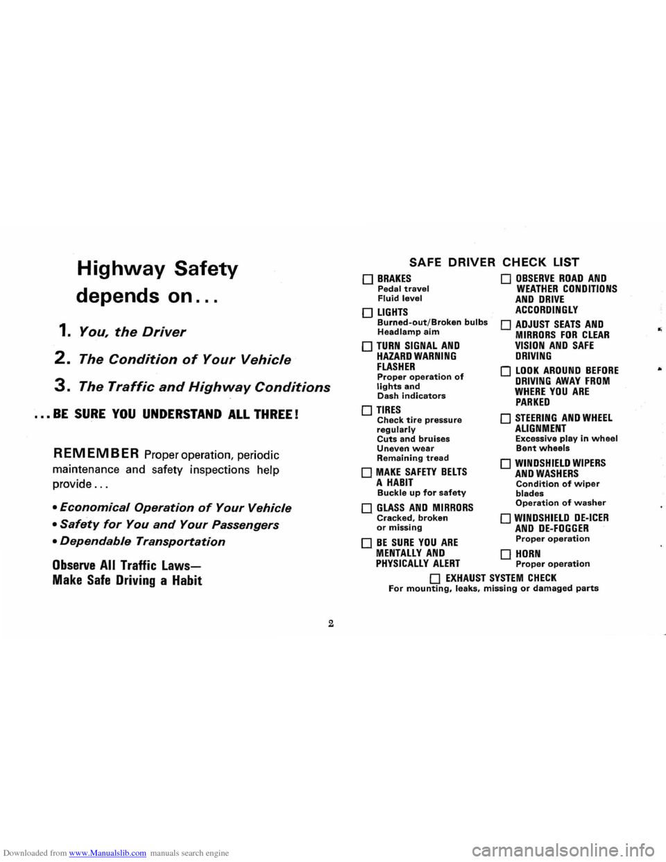
Downloaded from www.Manualslib.com manuals search engine Highway Safety
depends on ...
1. You, the Driver
2. The Condition of Your Vehicle
3. The Traffic and Highway Conditions
••• BE SURE YOU UNDERSTAND ALL THREE!
REMEMBER Proper operation, periodic
maintenance and safety inspections help
provide
...
• Economical Operation of Your Vehicle
• Safety for You and Your Passengers
• Dependable Transportation
Observe All Traffic Laws
Make Safe Driving a Habit
2
SAFE DRIVER CHECK LIST
o BRAKES Pedal travel Fluid level
o LIGHTS Burned-out/Broken bulbs Headlamp aim
o TURN SIGNAL AND HAZARD WARNING FLASHER Proper operation of lights and Dash indicators
o TIRES Check tire pressure regularly Cuts and bruises Uneven wear Remaining tread
o MAKE SAFETY BELTS A HABIT Buckle up for safety
o GLASS AND MIRRORS Cracked, broken or missing
o BE SURE YOU ARE
o OBSERVE ROAD AND WEATHER CONDITIONS AND DRIVE ACCORDINGLY
o ADJUST SEATS AND MIRRORS FOR CLEAR VISION AND SAFE DRIVING
o LOOK AROUND BEFORE DRIVING AWAY FROM WHERE YOU ARE PARKED
o STEERING AND WHEEL ALIGNMENT Excessive play in wheel Bent wheels
o WINDSHIELD WIPERS AND WASHERS Condition of wiper blades Operation of washer
o WINDSHIELD DE-ICER AND DE-FOGGER Proper operation
MENTALLY AND 0 HORN PHYSICALLY ALERT Proper operation
o EXHAUST SYSTEM CHECK For mounting, leaks, missing or damaged parts
Page 7 of 56
Downloaded from www.Manualslib.com manuals search engine A WORD ABOUT ... VEHICLE SAFETY AND THE INI
TIAL FEDERA~ MOTOR VEHICLE SAFETY STANDARDS
Chevrolet has for many years been a leader in the field
of automotive safety. Almost every advance in design and engineering since the jnception of the industry has contributed
to the safety, reliability and durability of our cars. Continua
tion of this important and vital trend is exemplified in your
1968 Chevrolet. Important safety advances are designed to
aid in avoiding accidents, and in reducing injuries during the accident and as a result of the accident.
But remember-it takes more than a safe car to avoid
accidents. Observe all traffic laws, make safe driving a habit and maintain your car in top condition.
Your
n!,)w 1968 Chevrolet conformed to all federal motor
vehicle safety standards applicable at time of manufacture.
Effectiveness of these safety features ~an best be continued
through periodic vehicle inspection and regular maintenance .
Th~ initial Federal Motor Vehicle Safety Standards encompass a number of systems on all passenger cars. To promote better understanding of these standards, listed are those
standards applicable to passenger cars, and the purpose and
scope of each.
Initial
Federal Motor Vehicle Safety Standards (Effective January 1, 1968*)
Amendment to certain of these
Standards and additional Standards that would apply to 1968 Model passenger cars
manufactured after January 1, 1968 , were under cons ideration by the National Highway Safety Bureau at the time this Owner's Manual was prepared. '
STANDARD NO. 101
Control Location and Identification
Purpose and Scope. This standard specifies the requirements
for location and identification of certain controls to facilitate
their selection and ensure their accessibility.
4
STANDARD NO. 102 Transmission Shift Lever Sequence, Starter Interlock, and Transmission Braking Effect Purpose and Scope. This standard specifies the requirements
for the transmission shift lever sequence, a starter interlock, and for a braking effect of automatic transmissions, to requce the likelihood of shifting errors, starter engagement with vehicle in drive position, and to provide supplemental braking at speeds below 25 miles per hour.
STANDARD NO. 103 Windshield Defrosting and Defogging Purpose lind Scope. This standard specifies requirements
for providing vision through the windshield during frosting and fogging conditions.
STANDARD NO. 104 Windshield Wiping and Washing Systems
Purpose and Scope. This standard specifies requirements
for windshi eld wiping and washing systems.
ST ANDARD NO. 105 Hydraulic Service Brake, Emergency Brake, and Parking Brake Systems
Purpose and Scope. This standard specifies requirements
for hydraulic service brake, emergency brake, and parking
brake systems intended to ensure adequate braking performance under normal and emergency conditions.
STANDARD NO. 106 Hydraulic Brake Hoses Purpose and Scope. This standard specifies requirements
for hydraulic brake hoses that will reduce brake failures due to fluid leakage.
STANDARD NO. 107 Reflecting Surfaces
Purpose and Scope. This standard specifies reflecting surface requir ements for certain vehicle components in the driver's field of view.
..
Page 8 of 56
Downloaded from www.Manualslib.com manuals search engine STANDARD NO. III Rearview Mirrors
Purpose and Scope. This standard specifies requirements for
rearview mirrors to provide the driver with a clear and rea
sonably unobstmcted view to the rear.
STANDARD NO. 203 Impact Protection for the Driver From the Steering Control System Purpose and Scope. This standard specifies requirements for
steering control systems that will minimize chest, neck, and facial injuries to the driver as a result of impact.
STANDARD NO. 204
Steering Control Rearward Displacement
Purpose and Scope. This standard specifies requirements
limiting the rearward displacement of the steering control
into the passenger compartment to reduce the likelihood of chest, neck, or head injury.
STANDARD NO. 205 Glazing Materials
Purpose and Scope. This standard specifies requirements
for glazing materials to reduce lacerations to the face, scalp, and neck, and to minimize the possibility of occupants being
thrown through the vehicle windows in collisions.
STANDARD NO. 206 Door Latches and Door Hinge Systems Purpose and Scope. This standard specifies load require
m ents for door latches and door hinge systems to minimize
the probability of occupants being thrown from the vehicle
in a collision.
STANDARD NO. 207 Anchorage of Seats Purpose and Scope. This standard establishes requirements
for seats, their attachment assemblies, and their installation
to minimize the possibility of failure by forces acting on the seat as a result of vehicle impact.
5
STANDARD NO. 208
Seat Belt Installations
Purpose and Scope. This standard establishes requirements
for seat belt installations.
STANDARD NO. 2090
Seat Belt Assemblies
Purpose and Scope. This standard specifies requirements
for seat belt assemblies.
STANDARD NO. 210
S ea t Belt Assembly Anchorages
Purpose and Scope. This standard specifies the requirements
for seat belt assembly anchorages to ensure proper location
for effective occupant restraint and reduce the likelihood
of failure in collisions.
STANDARD NO. 211
Wheel Nuts, Wheel Discs, and Hub Caps
Purpose and Scope. This standard precludes the use of wheel nuts, wheel discs, and hub caps that constitute a hazard to
pedestrians and cyclists .
STANDARD NO. 301 Fuel Tanks, Fuel Tank Filler Pipes, and Fuel Tank Con-
nections
Purpose
and Scope. This standard specifies requirements
for the integrity and security of fuel tanks, fuel tank filler
pipes, and fuel tank connections to minimize fire hazard as
a result of collision.
PUBLIC LAW 87·637 (1962) * An Act to provide that hydraulic brake fluid sold or shipped in commerce for use in motor vehicles shall meet cer
tain specifications prescribed by the Secretary of Commerce. The requirements of this law were issued as standards when the National Traffic and Motor Vehicle Safety Act of 1966
was enacted.
"The Sea t (Lap) Belt and Brak e fluid standards are applicable
to all 1968 models of affected vehicles.
Page 20 of 56
Downloaded from www.Manualslib.com manuals search engine If the system is not functioning properly, a legal hand
signal should be given, since failure to indicate a turn
is considered a moving traffic violation in many states.
Always signal for a turn
at a reasonable distance before actu 'ally making it.
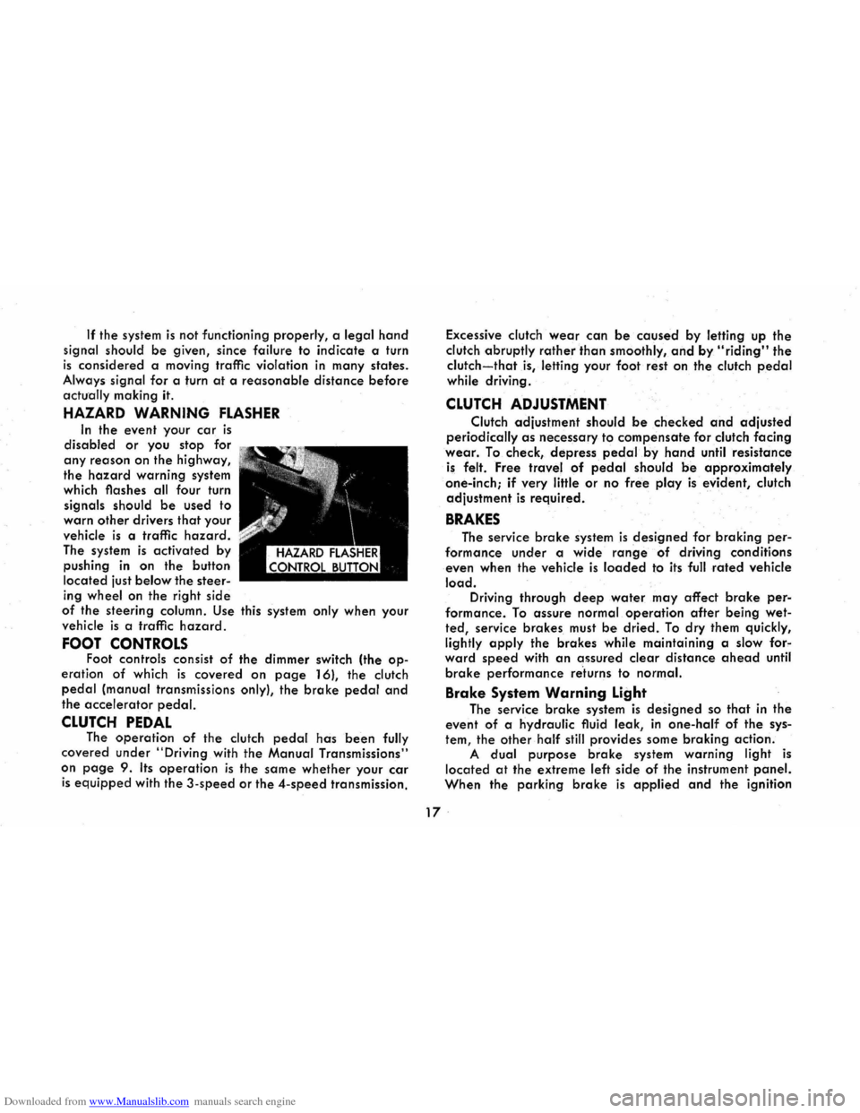
HAZARD WARNING FLASHER
In the event your car is
disabled or you stop for
any reason on the highway,
the
hazard warning system
which flashes all four turn
signals should
be used to
warn
other drivers that your
vehicle
is a traffic hazard.
The system is activated by
pushing
in on the button
located just
below the steer
ing wheel on the right side
of the steering column. Use this system only when your
vehicle
is a traffic hazard.
FOOT CONTROLS Foot controls consist of the dimmer switch (the op
eration of which is covered on page 16), the clutch
pedal (manual transmissions only), the brake pedal and
the accelerator pedal.
CLUTCH PEDAL The operation of the clutch pedal has been fully
covered under
"Driving with the Manual Transmissions"
on
page 9. Its operation is the same whether your car
is equipped with the 3-speed or the 4-speed transmission. Excessive
clutch
wear can be caused by letting up the
clutch abruptly
rather than smoothly, and by "riding" the
clutch-that is, letting your foot rest on the clutch pedal
while driving .
CLUTCH ADJUSTMENT
Clutch adjustment should be checked and adjusted
periodically as necessary to compensate for clutch facing
wear. To check, depress pedal.by hand until resistance
is felt. Free travel of pedal should be approximately
one-inch;
if very little or no free play is evident, clutch
adjustment
is required.
BRAKES
The service brake system is designed for braking per
formance under a wide range of driving conditions
even when the vehicle
is loaded to its full rated vehicle
load. Driving through deep water may affect brake per
formance. To assure normal operation after being wet
ted, service brakes must be dried. To dry them quickly,
lightly
apply the brakes while maintaining a slow for"
ward speed with an assured clear distance ahead until
brake performance re'turns to normal.
Brake System Warning Light
The service brake system is designed so that in the
event of a hydraulic fluid leak,
in one-half of the sys
tem, the other half still provides some braking action.
A dual purpose brake system warning light is
located at the extreme left side of the instrument panel.
When the parking brake is applied and the ignition
17 .
Page 21 of 56
Downloaded from www.Manualslib.com manuals search engine switch is turned to the "ON" position, the warning light
glows red to indicate to the operator that the parking
brake has not been fully released. This also indicates
that the brake warning light is operational. If the light does not come on, have your Corvair Dealer correct
the trouble as soon as possible. The other function of
this light is to indicate a malfunction in the regular braking system. In the event of broken brake lines,
major brake fluid loss, air in the brake lines or a pres
sure deviation between the front · and the rear wheel
brake lines, the light will come on and stay on while
braking .
In this event, the vehicle should not be driven
until
the cause has been determined and, if necessary,
corrected.
Automatic Brake Adjusters
All Corvair models are equipped with self-adjusting
brakes which eliminates periodic brake adjustments. The
self-adjusting mechanism
is actuated, as needed, when
ever the car is moved in reverse and the brakes applied.
It is possible, however, for excessive brake pedal travel
to
develop if the required reverse movement with a
brake application does not take place during a pro
longed
period of stop and go forward driving. Should
this occur,
the car should be driven backward and for
ward with the brakes applied at the end of each direc
tional movement, until the brake pedal travel is back to
normal. If this procedure fails to restore normal pedal
travel, or if any abnormally rapid increase in pedal
travel is experienced, immediate inspection should be
made by your Authorized Chevrolet Dealer. Care should
18
be exercised to assure that full brake pedal travel can
not be obstructed by improper floor mats or other inter
fering material under the pedal.
PARKING BRAKE
The parking brake operates by cables on the rear
wheel brakes independent of the regular foot brake hydraulic system. The brake system warning light will
be "ON" whenever the parking brake is not fully re
leased and the ignition switch is "ON". Never drive the car with the parking brake engaged. .
Pull the parking brake lever as far as possible to
engage the brake. The lever will remain in the applied
position until released. To release, pull the handle to
ward the steering wheel, depress the "trigger" and
allow the handle to return to the released position. CAUTION: When leaving the car unattended, always
fully apply the parking brake.
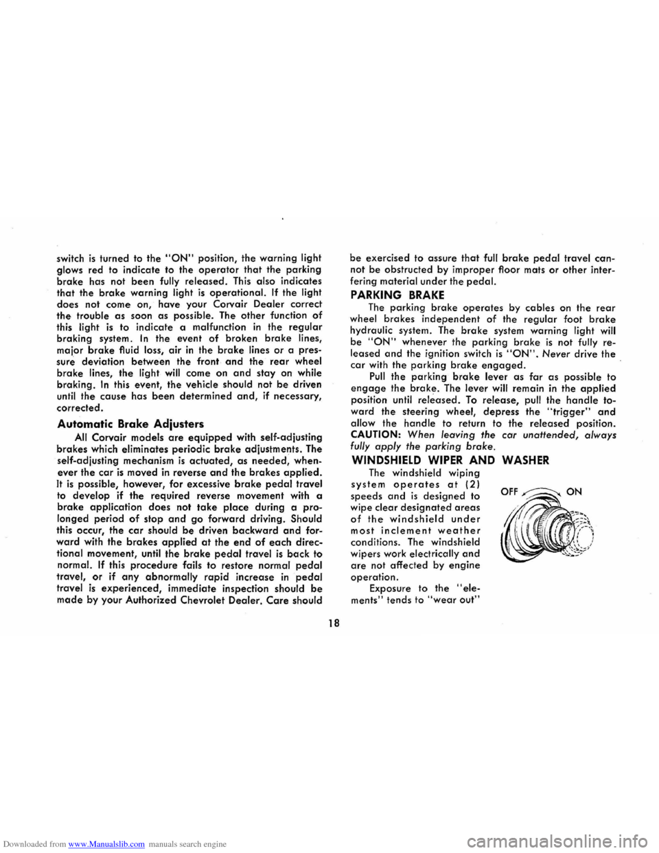
WINDSHIELD WIPER AND WASHER
The windshield wiping
system operates at (2)
speeds and is designed to
wipe clear
designated areas
of the windshield under
most inclement weather
conditions. The windshield
wipers work
electrically and
are not affected by engine
operation.
Exposure to the "ele
ments" tends to "wear out"
OFF~ON
Page 43 of 56
Downloaded from www.Manualslib.com manuals search engine TRANSMISSION CONTROL LlNKAGE-
3 AND 4-SPEED
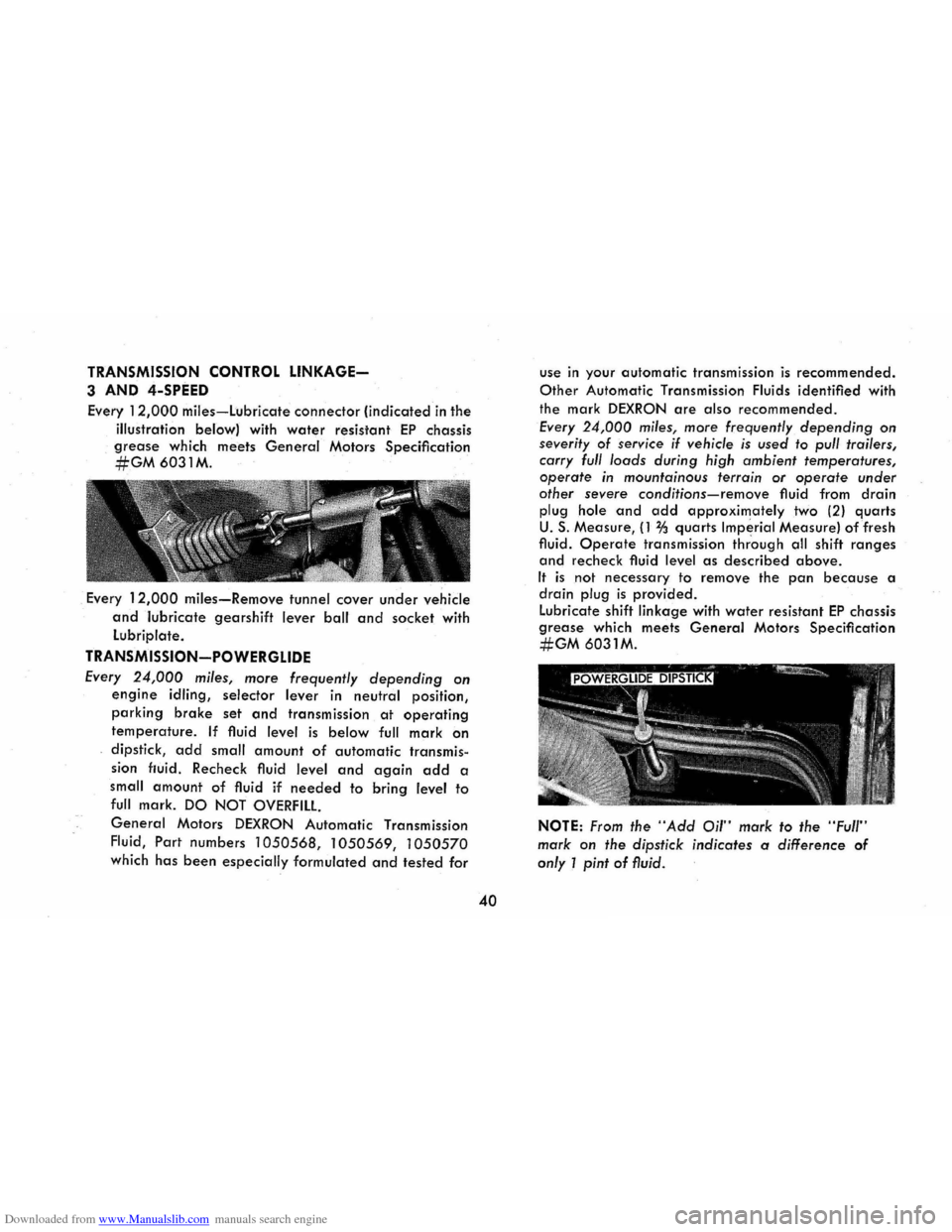
Every 12,000 miles-Lubricate connector (indicated in the
illustration below) with
water resistant EP chassis
grease which meets General Motors Specification
#GM6031M.
. Every 12,000 miles-Remove tunnel cover under vehicle
and lubricate gearshift lever ball and socket with
Lubriplate.
TRANSMISSION-POWERGLIDE
Every 24,000 miles, more frequently depending on
engine idling, selector lever in neutral position,
parking brake set and transmission at operating
temperature. If fluid level is below full mark on
dipstick, add small amount of automatic transmis
sion fluid. Recheck fluid level and again add a
small
amount of fluid if needed to bring level to
full mark. DO NOT OVERFILL
General Motors DEXRON Automatic Transmission
Fluid,
Part numbers 1050568, 1050569, 1050570
which has been especially formulated and tested for
40
use in your automatic transmission is recommended.
Other Automatic Transmission Fluids identified with
the mark
DEXRON are also recommended.
Every 24,000 miles, more frequently depending on
severity of service if vehicle is used to pull trailers,
carry full loads during high ambient temperatures,
operate in mountainous terrain or operate under
other severe
conditions-remove fluid from drain
plug hole and add approximately two (2) quarts
U. S. Measure, (1 % quarts Imperial Measure) of fresh
fluid.
Operate transmission thr'ough all shift ranges
and recheck fluid level as described above.
It is not necessary to remove the pan because a
drain plug is provided .
Lubricate shift linkage with
water resistant EP chassis
grease which meets General Motors Specification
#GM 6031M.
NOTE: From the "Add Oil" mark to the "Full"
mark on the dipstick indicates a difference of
only 1 pint of fluid.
Page 46 of 56
Downloaded from www.Manualslib.com manuals search engine AIR CONDITIONING
Have your Chevrolet Dealer check your air conditioning
system
at some time during the winter months to be
sure there has been no loss in cooling output. Dur
ing
the summer, see your Chevrolet Dealer immedi
ately if you suspect the system is not performing as
it should.
BRAKE LININGS
Brake linings should be periodically inspected for wear.
The frequency of this inspection depends upon driv
ing conditions such
as traffic or terrain, and also
the driving techniques of individual owners. Your
Chevrolet Dealer is best qualified to advise you as
to how often this inspection should be performed.
When brakes require relining use genuine General
Motors Parts or equivalent.
BRAKE MASTER CYLINDER
Every 6,000 miles-Check fluid level in each reservoir
and maintain % II below lowest edge of each open
ing with G.M. Hydraulic Brake Fluid Supreme No. 11
PARKING BRAKE AND CLUTCH PULLEYS
AND CABLES
Every 12,000 miles-lubricate pulleys under dash. Re
move. the tunnel cover under vehicle and lubricate
pulleys
and cable bearing points with a water resist
ant EP chassis grease which meets General Motors
43
Specification #GM 6031 M. Lubricate gearshift lever
ball and socket (see page 38) at the same time.
FRONT WHEEL BEARINGS
Clean, repack with high melting point wheel bearing
lubricant, and adjust whenever the wheels and hub
are removed. Replace grease seals at the same time.
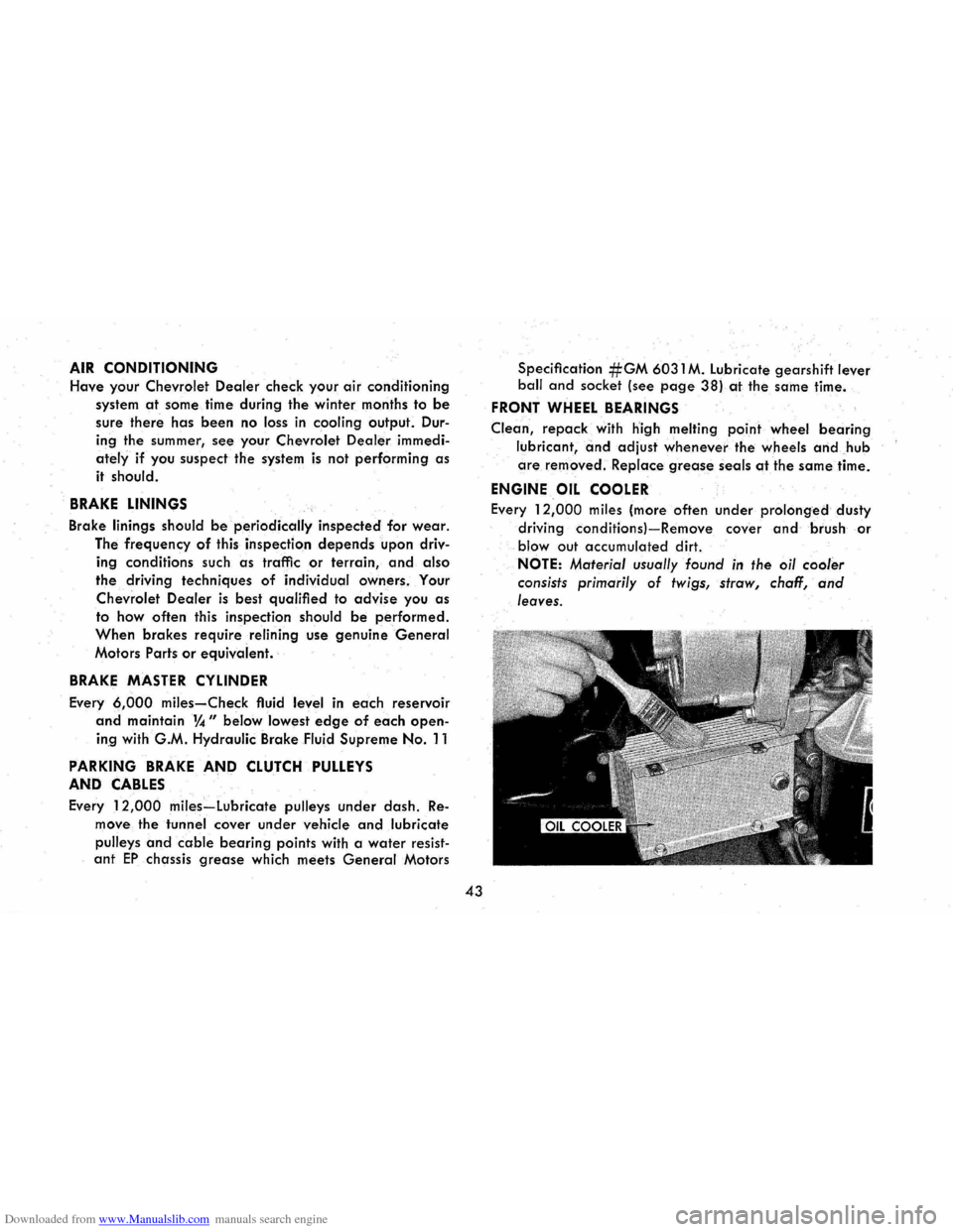
ENGINE OIL COOLER
Every 12,000 miles (more often under prolonged dusty
driving
conditionsl-Remove cover and brush or
blowout accumulated dirt.
NOTE: Material usually found in the oil cooler
consists primarily
of twigs, straw, chaff, and
leaves.